
Call 800-535-9545 | www.aeroindustries.com
Indianapolis, IN | Omaha, NE | Kent OH
Attention Dealers: Please give this manual to the customer when product is delivered.
Serving the Truck & Trailer Industry
Since 1944
Installation Instructions

Top Glide Pro
2
Installation Directory
Item Step Page
Important Safety Information 3
Trailer Configuration & Tools Required 4
Trailer Preparation (before installation) 5
Standard Top Glide Pro Vs. 6" Drop 6
Prepare Front Assembly for Installation 1a 7
Install Front Assembly 1b 8-9
Install Electrical Hardware (Electric Drive) 2a 10-12
Install Remote with Current Sense 2b 13-15
Lead Pup Schematic 2c 15
Install Crank Assembly (Manual Drive) 2d 16
Install Rear Idlers 3 17-18
Assembly Bows and Place on Trailer 4 19
Install Power Bow Extender (Optional) 5 20
Install Drive Cable 6 21-22
Install Wind Deflector 7 22
Install Tarp on Trailer 8a 23
Install Tarp on Ground (Optional) 8b 24-25
Set the Power Bow Location and Attach Tarp to Power Bow 8c 26
Attach Tarp to Wind Deflector 8d 26-27
Anti-Lift Installation 9 28
Install Label 10 29
Finish Installation 11 29
Setting Torque Limiter 12 30
Note: For the 6" drop see additional instruction booklet.

Top Glide Pro
3
This manual explains how to install and maintain the Top Glide Pro tarp
system.
Explanation of Signal Words
DANGER: Indicates a hazardous situation which, if not avoided will result in death
or serious injury.
WARNING: Indicates a hazardous situation which, if not avoided could result in
death or serious injury.
CAUTION: Indicates a hazardous situation which, if not avoided could result in
minor or moderate injury.
General Safety Messages
WARNING: Read this entire manual before installing and operating this product.
Read all safety messages before installing and operating.
WARNING: Be sure that your working platform is secure as you work on the truck.
Use OHSA approved ladders or scaffolding to work above ground level.
WARNING: Always wear safety glasses during installation and operation.
CAUTION: Keep all clothing clear of moving parts.
Important Safety Information
IMPORTANT: Contains information critical to installation, operation, or warranty policy.
NOTICE: Risk of product or vehicle being damaged.
NOTE: Contains information critical to the installation or operation of this product.

Top Glide Pro
4
Lifting Device
Marker or Felt Pen
Tape Measure
Hammer
Vice Grip Pliers (2 pair)
Razor Knife
Electric or Air Drill
Straight Edge
C - clamp (2)
Drill Bits: .257" (F drill), 9/32", .316" (O drill),
13/32", 17/32", 9/16"
Sockets: 7/16", 9/16"
Open End or Box Wrenches: 7/16", 9/16", 3/4"
Black Electrical Tape
1/4" cable x 5' long (2 pcs.)
1/4" cable clamps (4)
2" x 4" x 8' boards (2)
Tools Required for Installation
Trailer Congurations
The Top Glide Pro is designed for use on various makes and models of trailers.
Some original equipment manufacturers (OEM) trailers may need to be modified to
ensure efficient operation of the Top Glide Pro.
Preparation
Unpack box(es) and layout all parts. Check parts off of parts list to ensure you
have all components necessary to install on trailer.
NOTE: To ensure correct mounting, double check that you have the right mounting
brackets for the trailer you are installing. Variations in trailer manufacturing may require
Aero to produce different mounting brackets for different trailers.
Trailer Width
System Width
Cable Center
Sheave for Cable
Sheave for Cable
SYSTEM WIDTH

Top Glide Pro
5
Trailer Preparation (before installation)
The Top Glide Pro must be able to slide on the top rail from the rear of the dump all the way to the front.
Also all components must be able to mount without interference.
• Check the bulkhead and the front corners for:
• Obstructions that may interfere with mounting the front assembly.
• Angled or irregular surfaces that may require custom mounting brackets or hardware.
• Check to see if the bulkhead is square with the sides. Shims may be required so front assembly is
square with sides.
• Check top rail for:
• Is at and continuos (no gaps) from the front to the rear (including cab shield)
• If tapered front to back, taper must be continuous.
• Nothing preventing the bows (bolts, brackets, or pins) from traveling from the front to the rear.
• Check the rear of the trailer for:
• There are no obtrusion from properly mounting the rear idler.
• Flat surface to mount the rear idler
• Check sides of the trailer for:
• Rear idler can be mounted so the sheaves (pulleys) are the same width as the ones on the front
assembly.
• Idler location will not interfere with the lift gate or swing of the tailgate.
• Protrusions that would interfere with the operation of the cables and ant-lift.
Make required modications before installing unit.
Obtain special hardware that may be needed to mount components.
Make or purchase custom brackets needed to mount components securely.
Top rail is at and continuos (no gaps)
from front to rear (including cab shield).
Eliminate Gaps
Custom brackets may be
needed for mounting.
Top Glide Pro
6
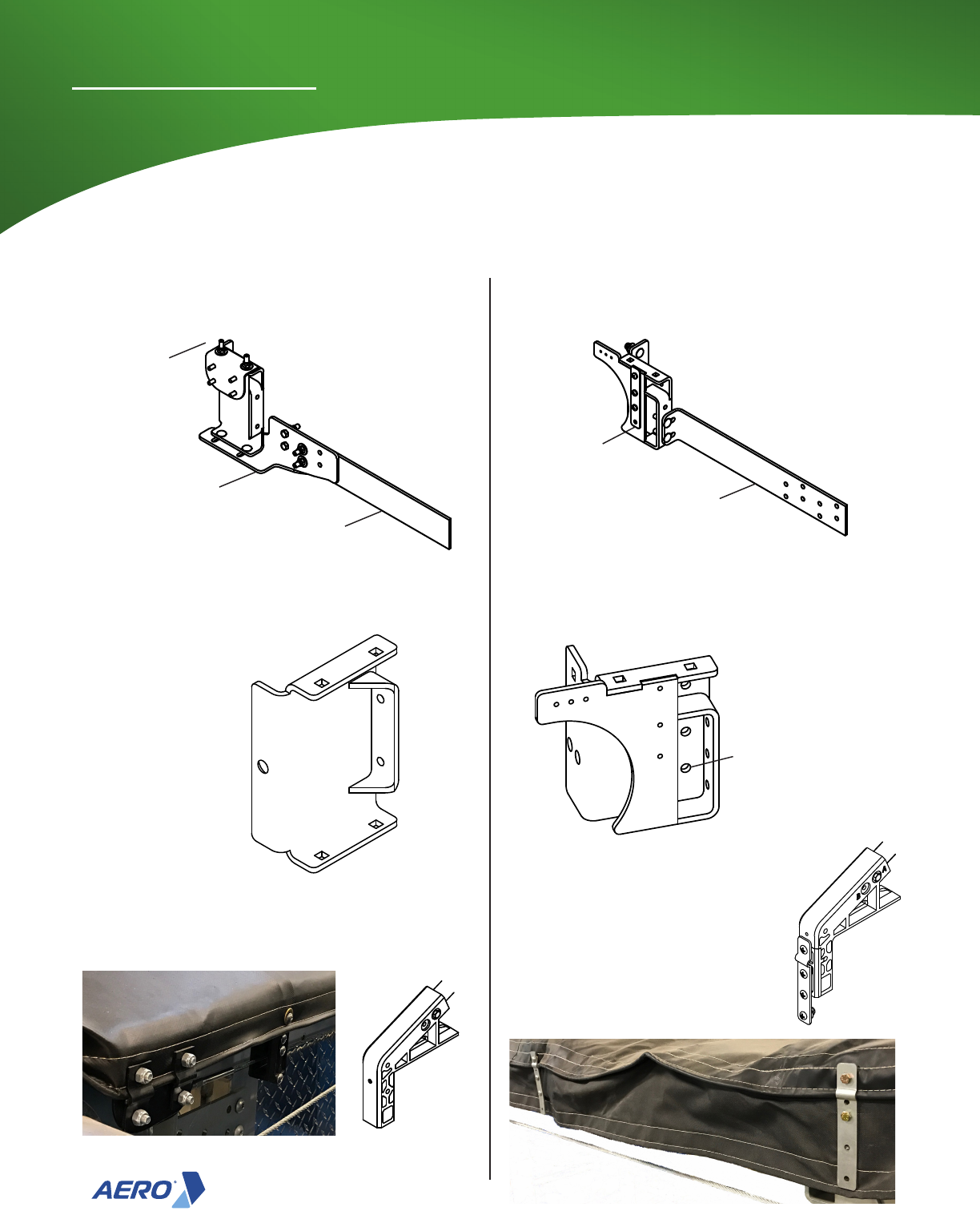
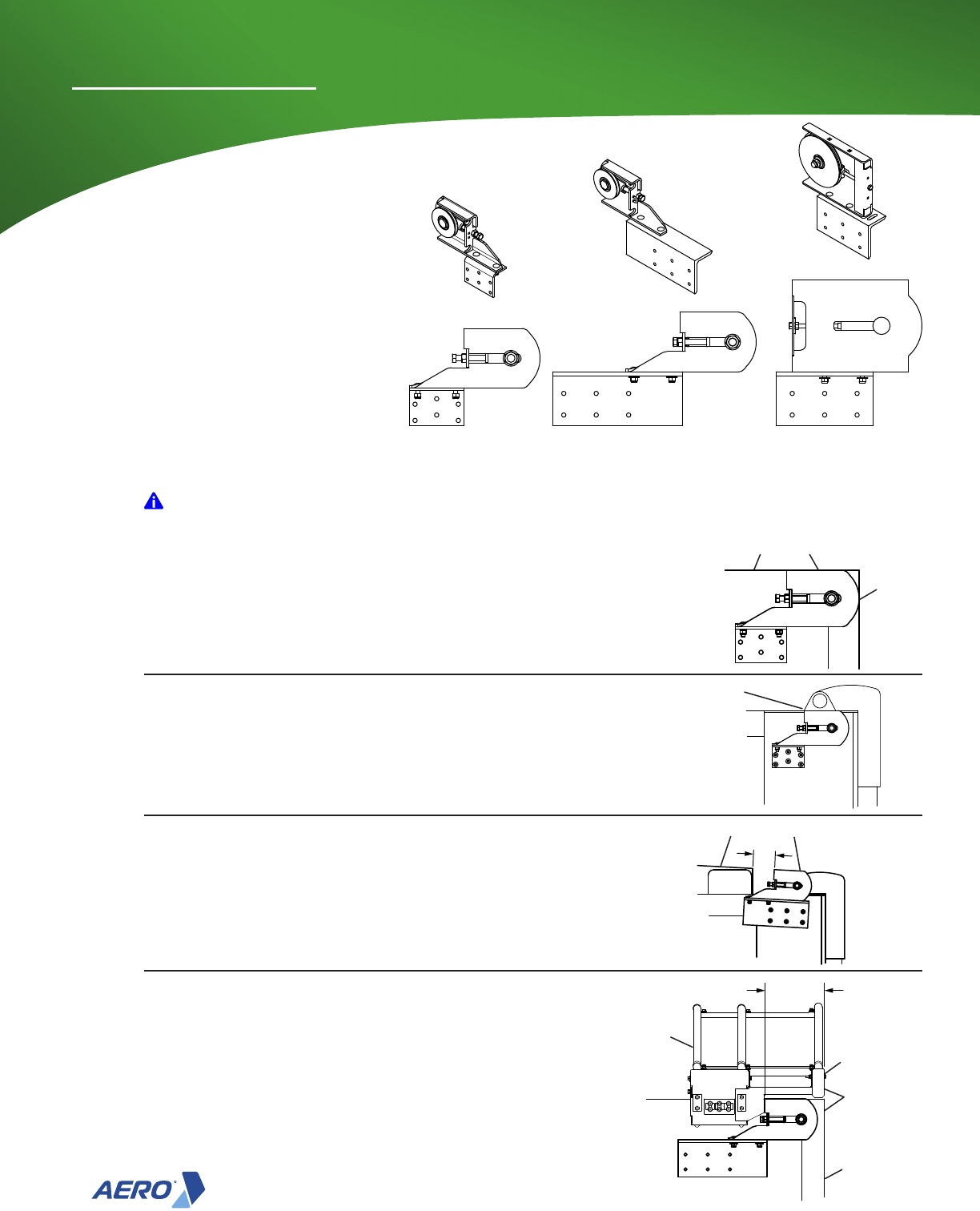
Front Assembly Mounting Brackets
Standard 6" Drop
Tarp Clamp
Tarp Clamp
Adjust mounting bracket
to width of bed.
Mounting Bracket
Extension Bracket
Extension Bracket
Shim to attach bracket
or adjust extension.
Mounting Holes
NOTE: See insert for mounting
6" drop front assembly
Standard Top Glide Pro Vs. 6" Drop
Tarp
Tarp
Bow End
Bow End
Note: For the 6" drop see additional
instruction booklet.

Top Glide Pro
7
Installation Instructions
Step 1a
Prepare Front Assembly for Installation
Note: The bows and tarp can be installed before or after
installing the front assembly and the rear idlers.
Hanger
Qty - 4
Note: Hanger brackets need to be removed when the top rail on the front of the trailer is
higher than the top rail on the sides like a raised bulkhead. (See graphics on following
pages)
Hanger
Qty - 4
Tension Cable
Bracket
Front Bracket Extension
Used on radius trailers
Mounting Bracket DS
Adjust all the way out
Move Brackets to sit on
at face of Bulkhead
Equally Spaced
Hanger
This is to prepare the front assembly to be attached to the bulkhead of the trailer.
Electric Manual
Top rail even height Raised Bulkhead
Tension Cable
Bracket
Mounting Bracket DS
Adjust all the way out
Front Bracket Extension
Used on radius trailers
Tarp Clamp
Mounting Brackets reversed
to clear obstruction
Mounting Brackets
typical mounting
Obstruction
Square Front without
extension
Extension without
hanger brackets
Square Front without
extension
Extension without
hanger brackets
Top Glide Pro
8
Installation Instructions
NOTE: TOP of drive sheaves must be 3/4" to 7/8"
BELOW top rail surface.
1a) Figure 1-1. Using lifting slings, place Front Assembly in
position with hanger brackets sitting on the top rail. A square
bulkhead does not need the mounting bracket extension.
Step 1b
Install Front Assembly
IMPORTANT: Trailers where the top rail is NOT the same height at the front and sides and the
hanger brackets are not used the Tension Cable Bracket is set flush with the top rail. Use a
straight edge flush to the top rail on both sides and 5" back or more from the front of the trailer can help
align front assembly.
2) Figure 1-4. Center Front Assembly so there is equal spacing on either side of trailer.
3) Figure 1-3 & 1-5. Align TOP of tension bracket ush with top rail. Hanger brackets places the unit at the
correct height.
STRAIGHT EDGE
TENSION
BRACKET
FLUSH
EXTENSION
NOTE: Front Assembly shown with
hanger brackets removed.
Square bulkhead
Top rail the same front and sides.
1b) Figure 1-2. Using lifting slings, place Front Assembly in
position without hanger brackets and align Tension Cable
Bracket with top of rail.
Straight edge
ush with top rail
Raised bulkhead
Top rail is NOT the same front and sides.
NOTE: Shown with Tarp Clamp removed.
3/4” - 7/8”
NOTE: If Glide Strips are to be installed they must be in
place before setting front assembly on trailer.
Figure 1-1
Figure 1-2 Figure 1-3
Align top of Tension Cable Bracket with top rail.
NOTE: Shown with Tarp Clamp removed.
Figure 1-5
Equal Spacing
Figure 1-4
Figure 1-6

Top Glide Pro
9
Installation Instructions
4) FIGURE 1-7. Verify Front Assembly is on center, square
to running surface, straight and at correct height.
7) Figure 1-9. Install side brackets with bolts, both sides of trailer.
Step 1b (cont.)
NOTE: Complete drive preparation next.
For Electric Drive see Electrical installation (STEP 2a)
For Manual Drive see Crank installation (STEP 2c)
NOTE: Shim front assembly out as needed to maintain
straightness. Drive shaft must not be installed
bent. Do NOT cause Front Assembly to bow.
90°
90°
8) Figure 1-10. Install Hanger brackets with Bolts.
Mounting Brackets
Adjust against dump body
6) FIGURE 1-8. Adjust mounting brackets
against the side of the dump body and
tighten bolts.
5) Verify side brackets are parallel to top rail running surface, then remove 2 x 4 x 8’ lumber if used.
3/8 X 1-1/2" TYPE F
21/64" drill into dump body
13/32" clearance hole in extension
13/32" drill
into dump body
3/8-16 X 7" Hex Bolt
3/8-16 Hex Nut Nylon Insert
3/8 Flat Washer
3/8 X 1-1/2" TYPE F or
3/8-16 X 7" Hex Bolt
3/8-16 Hex Nut Nylon Insert
3/8 Flat Washer
Figure 1-7
Figure 1-8
Figure 1-9
Figure 1-10

Top Glide Pro
10
Installation Instructions
Step 2a
Install Electrical Hardware
No. Part Number Description QTY
11
0755-626503 WIRE END #6 X 3/8 RING 6
12
0755-626507 WIRE END #6 X #10 RING 4
13
0755-626504 WIRE END #6 X 1/4 RING 2
14
0755-626553 WIRE END #14 x 3/8 RING 1
15
0755-626554 WIRE END #14 X 1/4 PUSH 6
16
0810-650500 BOLT 1/4-20 x 1 2
17
0810-650473 BOLT 1/4-20 x 2 2
18
0815-660456 LOCKNUT 1/4-20 JAM 4
19
0820-680410 WASHER FLAT 1/4" 6
20
0815-660307 NUT HEX 5/16-24 4
21
0820-680520 WASHER LOCK 5/16" 4
22
0815-660121 LOCKNUT #10-32 4
No. Part Number Description QTY
1
0755-962111 HARDWARE KIT (SEE NEXT) 1
2
0755-623510 CIRCUIT BREAKER 25A 2
3
0755-623560 REVERSING DC CONTACT 12V 1
4
0930-861628 WIRING DIAGRAM 1
5
0755-623559 CONTACTOR COVER 1
6
0755-962102 SWITCH - ROCKER 1
7
0850-603757 CLAMP -LOOM 5/8" I.D. 12
8
0755-626500 WIRE END #6 BUTT CONNCT 4
9
0755-626507 WIRE END #6 X #10 RING 8
10
0755-626503 WIRE END #6 X 3/8 RING 2
NOTICE: USING BREAKER GREATER THAN 25 AMP MAY RESULT IN MOTOR FAILURE.
0755-962104
RDCC ELEC KIT
0755-962111
RDCC HARDWARE KIT
MOTOR
MOTOR
Tractor
Trailer
Dump Truck

Top Glide Pro
11
Installation Instructions
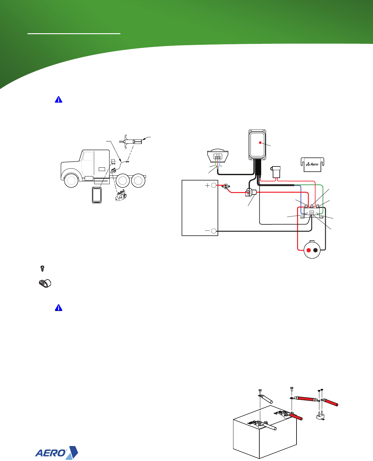
Step 2a
Truck Cab Wiring
1) Find a convenient place on the driver's side under the dashboard
to mount the rocker switch with 1/4-20 x 1" hex bolts
IMPORTANT: Locate Operation/Maintenance Sheet and keep near switch.
2) Mount reversing contactor in the battery box or
outside near back of cab with 1/4-20 x 2" hex bolts.
6) Connect the red wire to the breaker and
to the positive terminal on the battery and
secure with zip ties. Connect the black wire
to the negative terminal on the battery.
3) Run 3 #14 gray wires from switch to reversing contactor. Connect to wires to
the switch and the reversing contactor per schematic using supplied hardware.
IMPORTANT: Switch is not rated for outdoor use.
Semi-Trailer Trucks get a plug
To Motor
To Motor
T1 to Switch
To Battery
To Switch
T2 to Switch
Battery /
Breaker
4) Run #6 red/black wire from battery to reversing contactor. Secure all wire with clamps.
5) Connect #6 red/black wire to reversing
contactor per schematic.

Top Glide Pro
12
Installation Instructions
For End Dumps
6b) See Figure 20. Run #6 wire from receptacle to rear of
trailer, onto dump bed, back to the front of the trailer
and up to the motor. Secure all wire with clamps.
For Bottom Dumps
6c) See Figure 21. Run #6 wire from receptacle up
to the motor. Secure all wire with clamps.
For Dump Trucks
4a) See Figure 20. Run #6 wire from Reversing DC Contactor
to rear of trailer, onto dump bed, back to the front of the
trailer and up to the motor. Secure all wire with clamps.
4b) Run wires from reversing contactor
to plug, making sure there is
enough wire to reach the receptacle.
5b) Place cover on reversing contactor.
For Semi-Trailer Trucks
#6 WIRE
Circuit Breaker 25A
Wire End #6 X #10 Ring
Locknut #10-32
#6 Wire with Red Stripe
Motor Housing Assembly
7) Wire per schematic red stripe wire to circuit breaker
and black wire to brake wire and black wire.
MOTOR
#6 Wire
CIRCUIT BREAKER 25A
Wire End #6 X #10 Ring
LOCKNUT #10-32
#6 Wire with Red Stripe
Motor Housing Assembly
Brake
Wire
Go to Step 2a-7 at bottom of page
Step 2a (cont.)
POS
NEG
+
-
FWD
REV
POS
NEG
+
-
FWD
PLUG RECEPTACLE
Top Glide Pro
13
Installation Instructions
Step 2a
Install Smart Electronics Hardware
MOTOR
Tractor Trailer
Dump Truck
MOTOR
0755-960000 Smart Circuit Breaker
No. Part No. Description QTY
1
0755-623520 Kit,Cir Brk,Cur Sen,TF4 1
2
0755-962150 SMT CIR BRK HARDWARE PACK 1
0755-962150 SMT CIR BRK HARDWARE PACK
No. Part No. Description QTY
3
0755-962151 INSULATED .25" MALE SPADE 1
4
0755-962152 INSULATED .25" FEMALE 2
5
0825-670364 SCREW #10X1" PAN HEAD 4
43
5
NOTICE: USING BREAKER GREATER THAN 25 AMP MAY RESULT IN MOTOR FAILURE.
Top Glide Pro
14
Installation Instructions
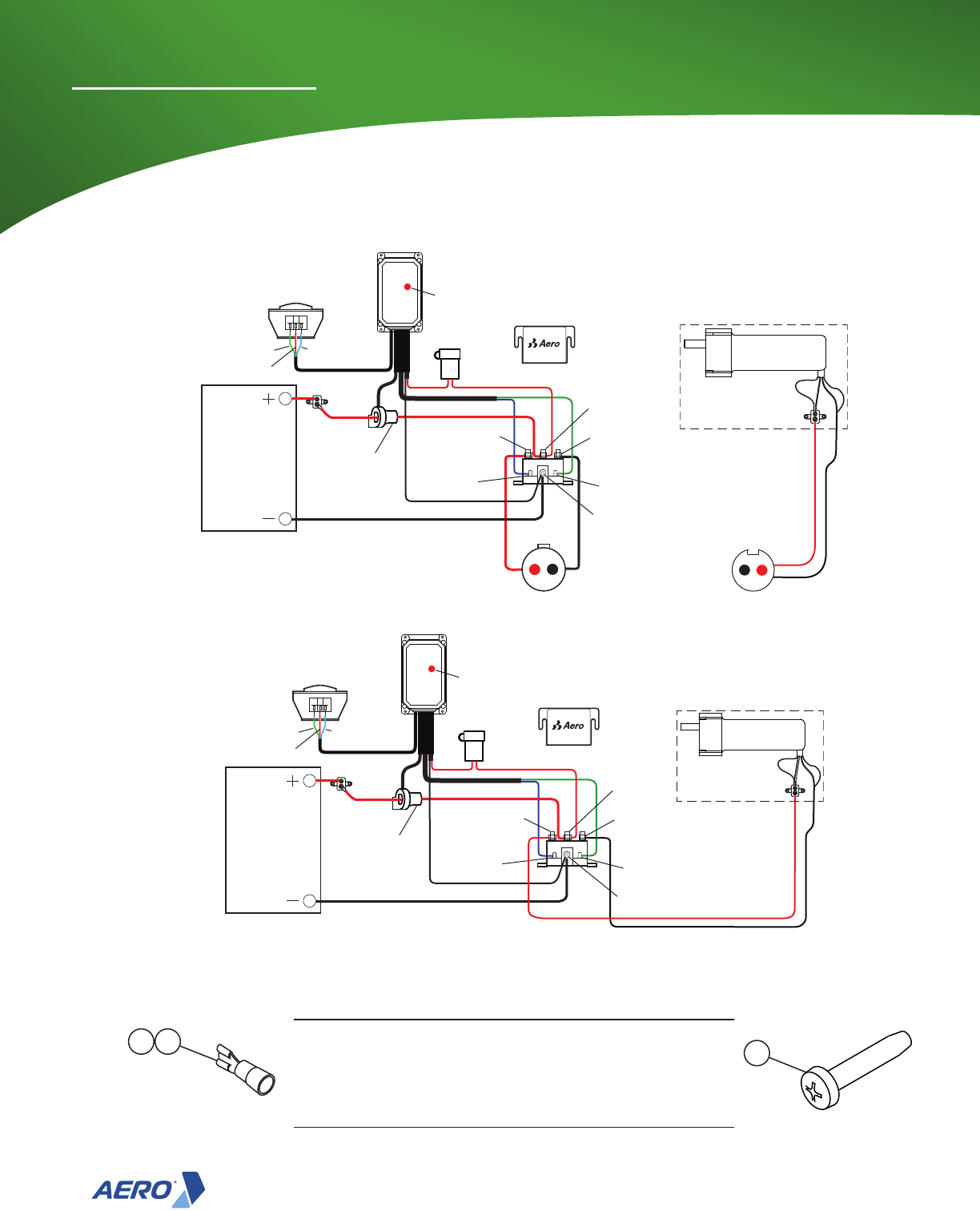
Step 2b
Smart Electronics
IMPORTANT: For best range select an open area to mount the controller outside the cab and not
surround by metal. Place in an area void of tire and road debris.
NOTE: This starts from Step 2a (3) before wiring the switch and the reversing contactor has
been mounted
2) Mount the tarp controller to the back of
the cab with the provided screws.
3) Run the cable from the tarp controller to the
reversing contactor. Secure with clamps.
7) Connect the black #6 wire and the black wire
from the tarp controller to GND terminal on
the reversing contactor.
6) Connect the red #6 wire and the red wire
from the 5 amp fuse (tarp controller) to +BAT
terminal on the reversing contactor.
5) Place the red #6 wire through the current sensor with
the tab pointing towards the end of the cable. Secure
the cable to the sensor with a zip tie.
1) Mount reversing contactor in the
battery box or outside near back of cab
with 1/4-20 x 2" hex bolts.
4) Run #6 red/black wire from the battery to reversing contactor. Secure all wire with clamps.
IMPORTANT: The tab on the current sensor must be pointed towards
the reversing contactor. If this sensor is backwards, the controller will not
operate in automatic mode. It will operate only as long as the button is held.
8) Connect the red wire to the breaker and to the positive
terminal on the battery and secure with zip ties.
9) Connect the black wire to the negative terminal
on the battery.
NOTE: For greater safety the 5A fuse can be
removed until the battery is connected.

Top Glide Pro
15
Installation Instructions
Step 2b (cont.)
10) Connect the green wire from the tarp
controller to terminal T2
11) Connect the blue wire from the tarp
controller to terminal T1
IMPORTANT: Switch is not rated for outdoor use.
13) Run 3 #14 gray wires from switch to tarp controller and secure with clamps.
Optional Cab Mounted Switch
12) Find a convenient place on the driver's side under the
dashboard to mount the rocker switch with 1/4-20 x 1" hex bolts
NOTE: Remember to put the 5A fuse back in if it was removed.
14) Connect wires to the switch and the tarp controller per schematic using
supplied hardware.
MOTOR
MOTOR
Step 2c
Lead Pup Schematic
IMPORTANT: Do NOT operate both switches at the same time.
Operating both switches at the same time will trip the breaker.

Top Glide Pro
16
Installation Instructions
Step 2d
Install Crank Assembly (manual drive only)
1) Figure 2-1. Wrap the Chain around the Sprocket on the Front Assembly.
2) Wrap the Chain around the Sprocket on the Crank Assembly and position the Crank Assembly at the
intended mounting location.
3) Figure 2-1. Trace the four mounting slots in the crank assembly onto the trailer, making sure the slots are
oriented vertically.
4) At the bottom edge of the slots just marked, drill four 11/32” holes through the trailer. Placement of the
holes is important to allow tensioning in paragraph 7 of this procedure.
CHAIN
CRANK
ASSEMBLY
NOTICE: Figure 2-2. Be sure the chain is properly aligned.
5) Mount the Crank Assembly onto the trailer and install the four 3/8” x
1-1/2” self-tapping screws (4) to hold the crank assembly in place at its
uppermost position. Do not completely tighten the screws at this time.
6) Wrap the chain around the sprockets and mark where the chain is to be
cut. Remove the pin at the mark and rewrap it around the sprockets.
Connect the ends of the chain using the master link.
7) Apply downward pressure on the crank assembly until the chain is taut.
Tighten the bolts.
Figure 2-1
Figure 2-2
Top Glide Pro
17
Installation Instructions
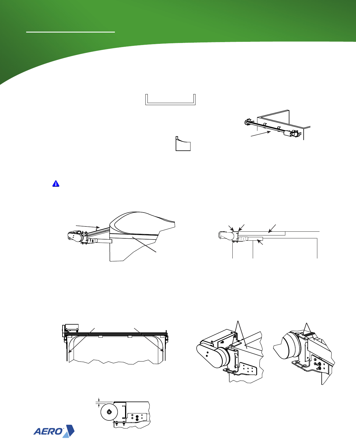
1) Positioning the Rear Idler.
• No obstructions on the top rail: set the back edge ush with
the rear most feature of the trailer (tailgate for example).
• Obstruction on top rail: set the front of the idler ush with the
obstruction. The power bow will stop 2" short of this point.
• Gap in top rail: set the front of the idler 2" behind where the
gap starts.
• Power Bow Extender: Front of idler is 8" from back of tailgate.
NOTE: 7" idler will extend past the tailgate 4". This could allow
the rear idlers to be hit and damaged.
2) Position rear idler ush and parallel with top rail and mark hole
locations.
Step 3
Install Rear Idler
NOTE: Top of rear idler needs to be flush to the top rail.
NOTE: Mounting bracket for rear idler needs to be parallel to the top rail.
2”
Flush and parallel
8.00
Power Bow
Extender
Tailgate
Power
Bow
Flush
Flush and parallel
Flush
Front ush with
obstruction
IMPORTANT: Avoid allowing the rear idler to extend past the tailgate or interfere with
the operation of the tailgate in any way (like 2-way tailgates).
NOTE: There are 3 different
Rear Idlers.
4" Steel Bracket
4" Aluminum Bracket
7" Aluminum Bracket
(6" Drop)

Top Glide Pro
18
Installation Instructions
5) Figure 3-2 & 3-3. Set sheave (pulley) center to center
measurement to match system width and tighten bolts.
4) Figure 3-1. Bolt Idler Angle Bracket to trailer both sides of trailer.
NOTE: Mount rear idler with 4 bolts thru, 2 bolts thru & 2 taping or 6 taping bolts.
3/8 X 1-1/2" TYPE F or
3/8-16 X 7" Hex Bolt
3/8-16 Hex Nut Nylon Insert
3/8 Flat Washer
SYSTEM WIDTH
SYSTEM WIDTH
21/64" drill into dump body
13/32" clearance hole in extension
13/32" drill into dump body
6) Figure 3-3 & 3-4 Verify Idler Assemblies are at correct width.
7) Figure 3-4 Verify rear Idler Pulleys are equal distance from front Drive
Sheaves.
8) Figure 3-4 Verify that diagonal 1 is equal to diagonal 2. This ensures
the system is square.
Align sheaves
and tighten bolts
D.S. Length
P.S. Length
99.00
105.00
99.00
105.00
Diagonal 1
Diagonal 2
Step 3 (cont.)
Figure 3-1
Figure 3-2
Figure 3-3
Figure 3-4

Top Glide Pro
19
Installation Instructions
NOTE: The bows can be attached to the tarp either on the ground or on the trailer.
NOTE: If Glide Strips are to be installed they must be in place before setting front assembly
on trailer!
NOTE: Top Glide Pro bows are shipped disassembled.
NOTE: One (1) plastic Bow End is bolted on each bow at the factory.
NOTE: Figure 4-1 to verify proper Bow End assembly and Bow End hole usage.
NOTE: Power Bows are assembled at the factory.
Step 4
Assembly Bows and Place on Trailer
B
A
A
B
SYSTEM WIDTH
1) Figure 4-3. Insert a bow end onto each end of a bow.
2) Figure 4-1 & 4-3. Bolt each bow end according to chart
above.
4) Figure 4-2. Verify cable hole center to center measurement
on all bows match system width (+/- 1/2").
1/4-20 x 1.75
Bolt
1/4 - Flat Washer
1/4-20 Nylon Lock Nut
5) Figure 4-4. Place power bow near rear idler and place
assembled bows together in front of the power bow.
IMPORTANT: Go to Step 6a if assembling
bows to tarp on the ground.
Figure 4-1
Figure 4-2
Figure 4-3
Figure 4-4

Top Glide Pro
20
Installation Instructions
Step 5
Install Power Bow Extender (Optional)
1) Figure 5-1 & 5-2. Remove nut and washer from the
bow assembly and attach the power bow extender
bracket. There is a driver side and a passenger side.
Note: The Bow Assembly for the power bow extender
has the bottom portion of the bow end removed.
Bow End
Bottom portion
removed
Bow Assembly
Power Bow Extender Bracket
Passenger Side Shown
2) Figure 5-3. Remove bolt, nut, and washer from the
power bow and attach the power bow extender bracket.
Remove bolt to attach
Power Bow Extender
3) Figure 5-4, 5-5, &5-6. Tie the 3 bows together with the bow
spacer strap.
• Use 1/4-20 x 3/4" hex bolt, conduit clamp, and 1/4-20
nylon hex nut to attach the bows.
• The center strap 3 washers are need under the conduit
clamp for the extender bow.
Add washers to extender
bow on center strap
Bow Spacer Strap
Conduit Clamp
1/4-20 x 3/4"
Hex Bolt
1/4 Flat Washer
1/4-20 nylon
Hex Nut
Center Strap
Figure 5-1
Figure 5-2
Figure 5-3
Figure 5-4
Figure 5-5
Figure 5-6

Top Glide Pro
21
Installation Instructions
1
2
6) Wrap drive cable (bottom cable run) around sheave on Rear Idler and route through Cable Clamp Assembly
from REAR to FRONT. Place a cable clamp securely (temporary) at the rear edge of power bow box.
2) Unwind drive cable removing any kinks. Lay the cable along
the length of the dump body with the two cable ends at the
rear.
3) Figure 6-2. Wrap the cable around the Front Drive Sheave.
Step 6
Install Drive Cable
4) Figure 6-2, 6-3, & 6-4. Route drive cable (top cable run) through the drive cable holes on Bow Ends and
through Cable Clamp Assembly from FRONT to REAR.
5) Figure 6-5 Place a cable clamp securely (temporary) at the rear edge of power bow box.
TARP NOT SHOWN
1) Figure 6-1 Adjust Rear Idlers all the way forward.
Front
Rear
Note: Front sheaves have a gripping taper. Once cable is inserted into groove it will become
difcult to slide.
Wrap Cable Around Sheave
Bottom cable Run
Sheave
Top cable Run
Accessory Hole
Drive Cable Hole
Anti-Lift Cable Hole
Bow End
Cable Clamp Assembly
Cable Clamps
Pull
Hex Nuts
Cable Clamp
Bottom cable Run
Top cable Run
Pull
7) Figure 6-5 Place cable clamp (temporary) on REAR end of drive cable so that it cannot slip out of bows.
9) Figure 6-5 Tighten all three (3)
Power Bow Cable Clamps.
8) Pull as much slack as possible from
cable,while keeping Power Bow
against Idler Brackets.
Figure 6-1
Figure 6-2
Figure 6-3
Figure 6-4
Figure 6-5

Top Glide Pro
22
Installation Instructions
10) Figure 6-6. Tension cable appropriately with Rear Idler
Adjustment Bolt.
Step 6 (cont.)
Adjustment Bolt
11) Repeat Steps 5.1 - 5.10 cable process on other side of trailer.
13) Figure 6-8. Remove temporary clamps. Cut cable 2”
from each side of the Power Bow. Apply heat shrink
tubing or tape to prevent cable fray.
2”
2”
12) Figure 6-7. Verify cables are equally tensioned by comparing
slack drop distance on each side.
Step 7
Install Wind Deector
1) Figure 7-1. Locate bolts in track
to match up with holes in the wind
deector.
2) Figure 7-1. Place wind deector on
front assemble and secure with 1/2"
washers and 1/2-13 nylon lock nuts.
1/2-13 Nylon Lock Nuts
1/2 Flat Washers
Bolts in Track
Wind Deector
SLACK
DROP
Figure 6-6
Figure 6-7
Figure 6-8
Figure 7-1

Top Glide Pro
23
Installation Instructions
3) Figure 8-2 Line up bows with aps underneath side of tarp and Bow Ends with
grommet in tarp.
4) Figure 8-3. Insert zip tie through hole in ap and wrap around Bow. Trim excess off
of zip tie.
2) Unfold Tarp and stretch across top of bows with the tail in the rear.
24.00
24.00
1) Figure 8-1 Space bow approximately 24" apart.
Step 8a
Install Tarp on Trailer
6) Figure 8-5. Pull tarp sections between bows UP to form uniform pleats.
7) Figure 8-6. Train pleats by crimping tarp edge cable between each bow and at the grommet.
5) Figure 8-4. Line up bow with grommet in tarp. Secure tarp to bow
ends via #14 X 1-1/4 Truss PH screw thru grommets on each side.
Flaps underneath
#14 X 1-1/4 Truss PH screw
Grommet in Tarp
Figure 8-1
Zip Tie through
hole around Bow
Zip Tie through
hole around Bow
Figure 8-3
Figure 8-2
Figure 8-4
Figure 8-5
Figure 8-6
Note: For the 6" drop see additional
instruction booklet.

Top Glide Pro
24
Installation Instructions
Step 8b
Install Tarp on Ground (Optional)
Zip Tie through
hole around Bow
Zip Tie through
hole around Bow
Flaps underneath
3) Figure 8-8. Line up bows with aps underneath and Bow Ends with grommet in tarp.
4) Figure 8-9 Insert zip tie through hole in ap and wrap around Bow. Trim excess off of
zip tie.
5) Figure 8-10. Line up bow with grommet in tarp. Secure tarp to bow
ends via #14 X 1-1/4 Truss PH screw thru grommets on each side.
#14 X 1-1/4 Truss PH screw
Grommet in Tarp
1) Figure 8-7. Unroll tarp upside down (aps for bows up)
on clean, at oor surface.
2) Figure 8-8. Align bows with aps on tarp.
Power bow is near the tail.
6) Figure 8-11, 8-12, & 8-13. Slide bows together and insert a 5’ length of 1/4" cable through accessory
hole of each single Bow End.
NOTE: DO NOT include power bow in stack up Figure 8-12.
NOTE: DO NOT insert cable into drive cable hole Figure 8-13.
Figure 8-7
Figure 8-8
Figure 8-9
Figure 8-10
Figure 8-11 Figure 8-12 Figure 8-13

Top Glide Pro
25
Installation Instructions
7) Figure 8-14. Place a clamp on one end of each cable.
8) Figure 8-15. Compress bow stack and lock in place with second cable clamp.
9) Figure 8-16. Turn tarp assembly right side up.
10) Figure 8-17. Pull tarp sections between
bows UP to form uniform pleats.
11) Figure 8-18. Train pleats by crimping
tarp edge cable between each bow.
12) Figure 8-19. Flip front tarp ap on top of tarp assembly.
13) Figure 8-20. Set power bow assembly on top of tarp assembly.
14) Figure 8-21. Place tarp assembly on top rails approximately 36" from rear of trailer.
36"
Step 8b (cont.)
Figure 8-14 Figure 8-15 Figure 8-16
Figure 8-17 Figure 8-18
Figure 8-19 Figure 8-20 Figure 8-21

Top Glide Pro
26
Installation Instructions
2) Figure 8-23. Pull tarp over edge of power bow
and place tarp cable between studs. Holes will
need to be punched in tarp to go top studs to
go through.
3) Place tarp bracket over studs and secure with
5/16-18 nylon hex nuts. 2 places on both sides
of the unit.
1) Figure 8-22. Run the system back until the power bow is 1" - 2" in front of the rear idler or the adjustment
bolt on the rear idler.
1" - 2"
1" - 2"
1" - 2"
Power Bow stops
at Adjustment Bolt
Power Bow Extension
stops at Rear Idler
Power Bow stops
at Rear Idler
Step 8c
Set the Power Bow Location and Attach Tarp to Power Bow
Tarp Bracket
Tarp Cable
5/16-18 nylon
hex nut
1) Figure 8-24. Pull tarp tight across wind deector (A).
Step 8d
Attach Tarp to Wind Deector
A
A
A
B
B
B
B
3) Run tarp towards the rear to stretch the tarp. If the power bow
hits the rear idler run the power bow forward approximately 1"
4) Remove screws from strap and pull tarp tight and replace strap
and screws.
5) Repeat this steps until power bow stops before hitting rear idler.
Note: It is important to pull tarp as tight as possible
to minimize the travel of the power bow when
closing the system.
2) Figure 8-24 Place tarp strap across mounting ledge and
insert self tapping screws (B). Continue to pull the tarp
tight at each screw location.
Figure 8-22
Figure 8-23
Figure 8-24

Top Glide Pro
27
Installation Instructions
Step 8d (cont.)
8) Figure 8-27. Trim excess tarp away from wind deector (C).
C
Trim Tarp
Tarp Bracket
5/16-18 nylon
hex nut
6) Figure 8-25. Pull tarp over edge of tarp bracket and place
tarp cable between studs. Holes will need to be punched in
tarp to go top studs to go through.
7) Figure 8-26. Place tarp bracket over studs and secure with
5/16-18 nylon hex nuts. 2 places on both sides of the unit.
11) Slowly, using drive unit, run the system forward and backwards to
test the system.
NOTICE: It is critical that power bow is advanced with care. If
any bows begin to tip or snag, STOP and realign immediately!
Figure 8-29.
9) Figure 8-28. Cut tarp cable (using cut off disk) a few inches
in front of the tarp bracket. Insert screw and washer into the
side of the wind deector and wrap the tarp cable around it and
tighten.
10) Repeat for both sides of trailer.
Tarp Bracket
5/16-18
nylon hex nut
Tarp Cable
Screw and
washer
Tarp Cable
Figure 8-25
Figure 8-26
Figure 8-27
Figure 8-28
Figure 8-29

Top Glide Pro
28
Installation Instructions
Step 9
Anti-Lift Installation
1) Figure 9-1. Insert tension cable into tension bracket and start nut onto threads.
2) Run tension cable thru all bows.
3) Figure 9-2. Loop return at U-bolt on idler bracket. Pull tight as possible by hand and install cable clamp.
DO NOT OVER TIGHTEN!
4) Figure 9-1. Increase tension using the adjustment nut onto threaded end to tension cable.
5) Figure 9-1. Tighten the lock nut.
6) Figure 9-2. Cut any excess cable at the rear.
7) Figure 9-3. Install chain bracket 1” BEHIND center
most bow, 1/4” BELOW lower drive cable.
8) Figure 9-3. Install chain assembly as indicated,
locate BETWEEN center bow and chain bracket.
9) Repeat Installation for other side of trailer.
TENSION
CABLE
TENSION
BRACKET
ADJUSTMENT NUT
LOCK NUT
Figure 9-1
CABLE CLAMP
TENSION CABLE
Figure 9-2
INSTALLATION
VIEW
DRIVER SIDE
FRONT
REAR
DRIVE CABLE
TENSION CABLE
DRIVE CABLE
RETURN
Figure 9-3
1) Figure 10-1. Notice label should be located on the driver’s side near the front of the trailer and 6’ from the
ground in a location easily seen. The label should be unobstructed and moving parts should NOT be able
to block or remove by motion. Clean area to apply label with soap and water and let completely dry. If label
becomes unreadable from debris, clean with mild soap, replace if label is unreadable when clean.
Step 10
Install Label
6'
Figure 10-1

Top Glide Pro
29
Installation Instructions
Step 11
Finish Installation
1) Test installation by cycling unit open / close.
2) Run unit to closed position.
3) Verify all fasteners are properly installed.
4) Verify tarp is secure and properly tensioned.
Note: The Motor is equipped with a Torque Limiter (clutch) to protect the TG Pro system
from excessive forces. If slippage occurs on new system, verify that the bed rail is
clear of obstructions and system is properly aligned. If slippage occurs during normal
operation, follow the procedures listed to adjust the Torque Limiter.
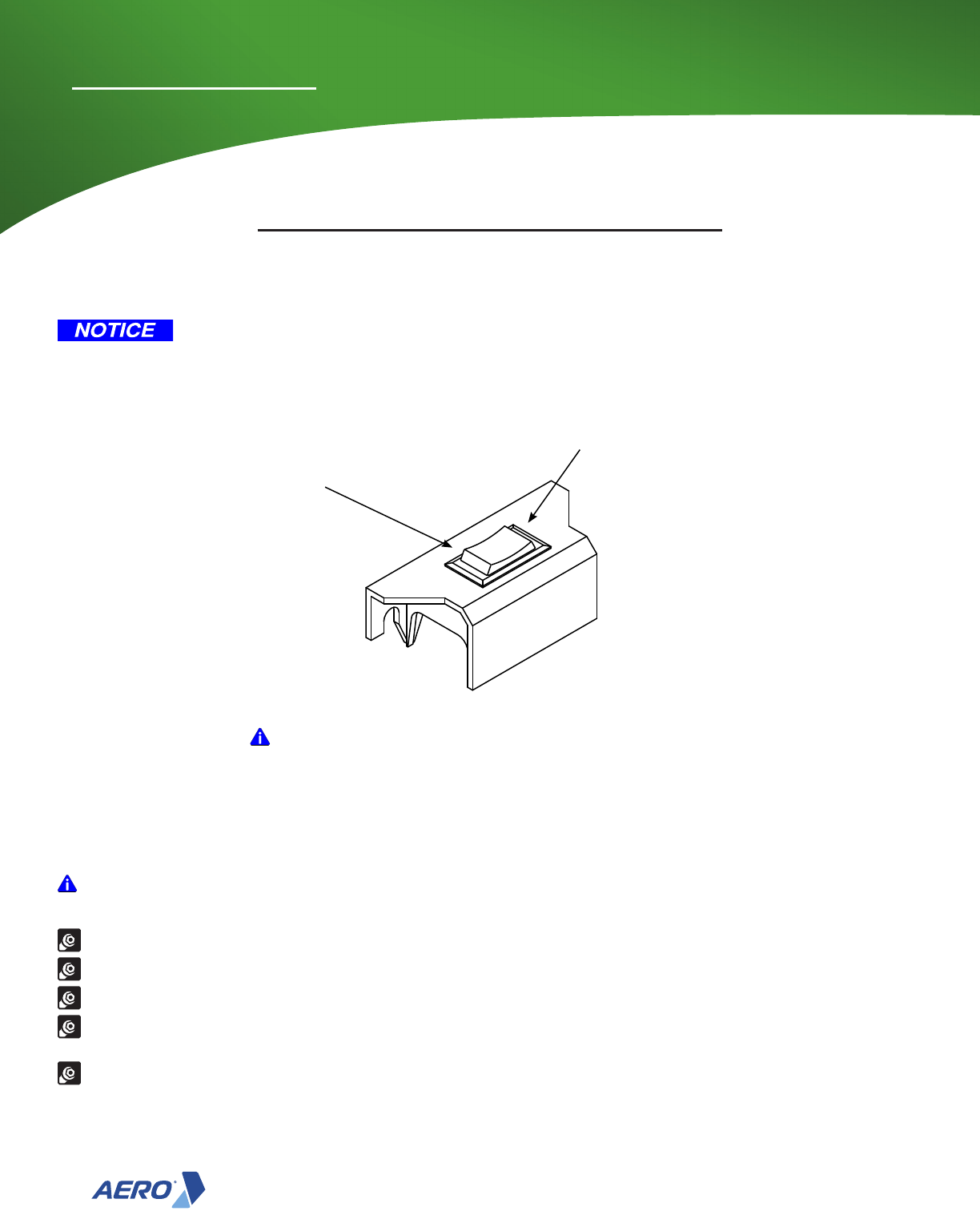
1) Located on the Torque Limiter, you will nd a large hex
nut. This large hex nut is captured by sheet metal tabs to
keep the nut from rotating. Bend these sheet metal tabs
back away from the large hex nut. Allow enough clearance
for the hex nut to turn.
2) Using a Torque Wrench with Socket, increase torque
setting by 2 ft-lbs.
3) Try tarping system to see if the system is still slipping.
Step 12
Setting Torque Limiter
Torque Limiter
CAUTION: Use care when making any adjustments to the Torque Limiter.
NOTICE: Over tightening of the Torque Limiter will cause damage to the Motor or the
tarping system. Do not exceed 40 ft-lbs.
Note: The Motor is equipped with a Torque Limiter (clutch) to protect the TG Pro system
from excessive forces. It is preset at the factory to 35 ft-lbs, If slippage occurs on
new system, verify that the bed rail is clear of obstructions and system is properly
aligned. If slippage occurs during normal operation, follow the procedures listed
below to adjust the Torque Limiter.
4) If the tarping system is still slipping, increase torque setting by 2 ft-lbs tighter. Repeat instructions 2 and 3
until the slipping has been eliminated. Do not exceed 40 ft-lbs.
5) Once the slipping has been eliminated, bend as many sheet metal tabs as possible over the ats of the hex
nut to lock it into place.
Top Glide Pro
30
Installation Instructions
Direction switch operates depends on how it is wired.
Operation Instructions
NOT releasing the switch when in the covered or uncovered position is reached
may cause the motor to burn out.
Push to cover unit and release
when fully covered.
Push to uncover unit and release
when fully uncovered.
Aero Industries recommends a weekly inspection of the following items:
IMPORTANT: Replace all worn or broken parts immediately.
Repairs must ONLY be made after proper instruction.
Inspect Tarp for wear and tears.
Inspect cables for broken wires.
Nuts & Bolts: Make sure all mounting bolts and nuts are in place and tight and that no parts are worn or damaged.
Bearings: Pull the shafts from side to side and in and out. If there is excessive play, replace the bearings. Apply
penetrating oil lightly as needed.
Electrical Connections: Check all electrical connections and tighten any loose connections.
Replacement Parts and instructions may be obtained from your Aero dealer or by contacting Aero Industries.
Maintenance Recommendations
Top Glide Pro Electric Model
IMPORTANT: Do NOT operate both switches at the same time.
Operating both switches at the same time will trip the breaker.
Lead Pup
Operation

Top Glide Pro
31
Installation Instructions
Top Glide Pro Manual Model
Maintenance Recommendations
Aero Industries recommends a weekly inspection of the following items:
IMPORTANT: Replace all worn or broken parts immediately. Repairs must ONLY be made after proper
instruction.
Inspect Tarp for wear and tears.
Inspect cables for broken wires.
Bearings: Pull the shafts from side to side and in and out. If there is excessive play, replace the bearings. Apply
penetrating oil lightly as needed.
Fasteners: Make sure all mounting bolts and nuts are in place and tight and that no parts are worn or damaged.
Chain: Check the chain tension, that links move smoothly, and make sure the master link is on. Lubricate the chain
regularly with penetrating oil.
Replacement Parts and instructions may be obtained from your Aero dealer or by contacting Aero Industries.
Crank handle is only used for uncovering. Remove and store crank handle when not in use.
Lift crank handle and
rotate crank unit to
open or closed.
Lift crank handle
and rotate to place
in notch to lock tarp
into position.
Crank unit open or closed.

Top Glide Pro
Call 1-800-535-9545
www.aeroindustries.com
INDIANAPOLIS, IN
Indianapolis, IN 46241
800-535-9545
FAX: 317-244-1311
OMAHA, NE
Omaha, NE 68137
800-535-9545
FAX: 402-895-6129
KENT, OH
Kent, OH 44240
888-237-2262
FAX: 330-626-3277
Aero Industries, Inc. 0930-022806 10/05/16 Rev F
© 2017 Aero Industries, Inc.
US: 4854630, 6139085, 6481779, 6582007, other patents pending
Canada: 2455928, 2574047
