
Your Power Solutions Partner
Cordex 24-3.1kW
Modular Switched Mode Rectifier System
Installation & Operation Manual
Part # 030-803-J0
Effective: 02/2014
member of The Group
™

9400010-J1 Rev A
Important Safety Instructions
SAVE THESE INSTRUCTIONS:
This manual contains important safety instructions that must
be followed during the installation, servicing, and maintenance of the product. Keep it in a safe place. Review the
drawings and illustrations contained in this manual before proceeding. If there are any questions re
g
ar
d
ing the safe
installation or operation of this product, contact Alpha Technologies or the nearest Alpha
representa
tive. Save this
document for future referen
c
e.
Safety Symbols
To reduce the risk of injury or death, and to ensure the continued safe operation of this product, the following symbols
have been placed throughout this manual. Where these symbols appear, use extra care and attention.
The use of ATTENTION indicates specific regulatory/code requirements that may affect the
placement of equipment and /or installation procedures.
NOTE:
A NOTE provides additional information to help complete a specific task or
procedure.
CAUTION!
CAUTION indicates safety information intended to PREVENT DAMAGE to material or
equipment. Cautions are designated with a shock hazard icon, the word CAUTION,
and a rule beneath which the information appears.
WARNING!
WARNING presents safety information to PREVENT INJURY OR DEATH to
personnel. Warnings are indicated by a shock hazard icon, the word WARNING, and
a rule beneath which the information appears.
HOT!
The use of HOT presents safety information to PREVENT BURNS to the technician
or user.
General Safety
WARNING!
This system is designed to be installed in a restricted access location that is
inaccessible to the general public.
Mechanical Safety
• Keep hands and tools clear of fans. Fans are thermostatically controlled and switch on automatically.
• Power supplies can reach extreme temperatures under
load.
•
Use caution around sheet metal components and sharp
edges.

9400010-J1 Rev A
Electrical Safety
WARNING!
Hazardous voltages are present at the input of power systems. The DC output from
rectifiers and batteries, though not dangerous in voltage, has a high short-circuit
current capacity that may cause severe burns and electrical arcing.
Before working with any live battery or power system, follow these precautions:
• Remove all metallic jewelry, such as watches, rings, metal rimmed glasses, or ne
c
kla
c
es
• Wear safety glasses with side shields at all times during the installation.
• Use OSHA approved insulated hand tools.
WARNING!
Lethal voltages are present within the power system. Always assume that an electrical
connection or conductor is energized. Check the circuit with a voltmeter with respect to
the grounded portion of the enclosure (both AC and DC) before performing any
installation or removal procedure.
• Do not work alone under hazardous
conditions.
• A licensed electrician is required to install permanently wired equipment. Input voltages can range up to
• 240 Vac. Ensure that the utility power is disconnected and locked out before performing any installation or
removal
pr
ocedur
e.
• Ensure that no liquids or wet clothes come into contact with internal
components.
• Hazardous electrically live parts inside this unit are energized from the batteries even when the AC
input
power
is
disconnected.
Battery Safety
• Servicing and connection of batteries must be performed by, or under the direct supervision of,
personnel
knowledgeable of batteries and the required safety
pr
ecautions.
• Always wear eye protection, rubber gloves, and a protective vest when working near batteries. Remove all
metallic objects from your hands and
neck.
• Use OSHA approved insulated hand tools. Do not rest tools on top of
batteries.
• Batteries contain or emit chemicals known to cause cancer and birth defects or other reproductive harm.
• Battery post terminals and related accessories contain lead and lead compounds. Wash your hands after
handling
batteries.
WARNING!
Follow battery manufacturer’s safety recommendations when working around battery
systems. Do not smoke or introduce an open flame when batteries (especially vented
batteries) are charging. When charging, batteries vent hydrogen gas, which can
explode.
• Batteries are hazardous to the environment and should be disposed at a recycling facility. Consult the
bat
tery
manufacturer for recommended local authorized r
ecyclers.

#9400011-J1 Rev A
Seguridad
GUARDE ESTAS INSTRUCCIONES:
Este manual contiene instrucciones de seguridad
importantes que deben seguirse durante la instalación, reparación y mantenimiento del producto. Manténgalas
en un lugar seguro. Inspeccione los dibujos y las ilustraciones contenidas en este manual antes de continuar. Si
existe cualquier pregunta relacionada con la instalación u operación segura de este producto, póngase en
contacto con Alpha Technologies o con su representante de Alpha más cercano. Guarde este documento para
referencia futura.
Símbolos de Seguridad
Para reducir el riesgo de lesión o muerte y para asegurar la operación continua segura de este producto, se han
colocado los siguientes símbolos a lo largo de este manual. En las partes donde aparecen estos símbolos, preste
atención y cuidado adicional.
Atención:
El uso de ATENCIÓN indica requisitos de código o regulatorios específicos que pueden
afectar la ubicación del equipo y/o los procedimientos de instalación.
NOTA:
Una NOTA (NOTE)provee información adicional para ayudar a completar una tarea o un
procedimiento específico.
¡CUIDADO
!
CUIDADO (CAUTION) indica información de seguridad con el propósito de PREVENIR
DAÑOS al material o al equipo. Los avisos de cuidado están designados con un icono de
peligro de choque, la palabra CUIDADO y una línea debajo de la cual aparece la
información.
¡ADVERTENCIA
!
Una ADVERTENCIA (WARNING) presenta información de seguridad para PREVENIR LESIÓN O
MUERTE al personal. Las advertencias se indican con un icono de peligro de choque, la palabra
ADVERTENCIA y una línea debajo de la cual aparece la información
¡CALIENTE!
El uso de CALIENTE (HOT) presenta información de seguridad para PREVENIR
QUEMADURAS al técnico o al usuario.
Seguridad General
¡ADVERTENCIA
!
Este sistema está diseñado para instalarse en una ubicación con acceso restringido
que no sea accesible para el público general.
Seguridad Mecánica
• Mantenga las manos y las herramientas alejadas de los ventiladores. Los ventiladores están controlados de forma
termostática y se encienden automáticamente.
• Las fuentes de alimentación pueden alcanzar temperaturas extremas bajo carga.
•
Tenga cuidado cerca de bordes filosos y componentes de chapa
.

#9400011-J1 Rev A
Seguridad Eléctrica
¡ADVERTENCIA
!
Hay voltajes peligrosos en la entrada de los sistemas de alimentación. La salida de CC de
rectificadores y baterías, si bien no es peligrosa en cuanto al voltaje, cuenta con una alta
capacidad de conducción de cortocircuito que puede causar quemaduras graves y arcos
eléctricos.
Antes de trabajar con una batería activa o un sistema de alimentación, siga estas precauciones
:
• Quítese toda joyería metálica, como relojes, anillos, anteojos con montura de metal o collares.
• Use antiparras de seguridad con protecciones laterales en todo momento durante la instalación.
• Use herramientas manuales aisladas aprobadas por OSHA.
¡ADVERTENCIA
!
El sistema de alimentación presenta voltajes mortales en su interior. Suponga
siempre que las conexiones o los conductores eléctricos están energizados. Revise el
circuito con un voltímetro con respecto de la porción a tierra del cerramiento (tanto
CA como CC) antes de realizar cualquier procedimiento de instalación o remoción.
• No trabaje solo en condiciones peligrosas
.
• Se requiere que un electricista matriculado se ocupe de instalar equipos con conexión permanente. Los
voltajes de entrada pueden llegar a los 240 VCA. Asegúrese de que la fuente de alimentación eléctrica del
servicio esté desconectada y bloqueada antes de realizar un procedimiento de instalación o remoción.
• Asegúrese de que ningún líquido ni ropa húmeda en contacto con los componentes internos
.
• Las partes eléctricamente activas peligrosas dentro de esta unidad están energizadas por las baterías incluso
cuando se desconecta la alimentación de entrada de CA
.
Seguridad de la Batería Externa
• El mantenimiento y la conexión de las baterías debe ser realizado por, o bajo la supervisión directa de,
personal experto en baterías y tomando las precauciones de seguridad requeridas
.
• Siempre que trabaje con baterías utilice protección para los ojos, guantes de goma y un chaleco protector.
Quítese todos los objetos metálicos de las manos y el cuello
.
• Use herramientas manuales aisladas aprobadas por OSHA. No apoye las herramientas sobre las baterías
.
• Las baterías contienen o emiten elementos químicos que causan cáncer y defectos de nacimiento u otros
problemas reproductivos.
• Los terminales de batería y accesorios similares contienen plomo y compuestos del plomo. Lávese las manos
después de manipular baterías
.
¡ADVERTENCIA!
Siga las recomendaciones del fabricante de las baterías cuando trabaje cerca de
sistemas de baterías. No fume ni introduzca una llama abierta cuando las baterías
(en especial las baterías ventiladas) se están cargando. Mientras se cargan, las
baterías ventilan gas hidrógeno que puede explotar.
• Las baterías son peligrosas para el medioambiente y deben desecharse en un centro de reciclado. Consulte al
fabricante de las baterías acerca de centros de reciclado autorizados locales recomendados
.

9400012-J1 Rev A
Sécurité
CONSERVEZ CES INSTRUCTIONS:
Le présent manuel contient des consignes de sécurité importantes
à suivre pendant l'installation, l'entretien et la maintenance du produit. Rangez-le dans un endroit sûr. Examinez les schémas et illustrations
contenus dans ce manuel avant de poursuivre. En cas de questions sur l'installation ou le fonctionnement en toute sécurité de ce produit,
contactez Alpha Technologies ou le représentant d'Alpha le plus près. Conservez ce document pour référence future.
Symboles de Sécurité
Pour réduire le risque de blessures ou d'accident mortel et assurer le maintien de conditions d'exploitation sécuritaires de ce produit,
les symboles ci-après ont été utilisés systématiquement dans ce manuel. Lorsque ces symboles sont utilisés, prenez des précautions
supplémentaires.
L'utilisation du symbole « ATTENTION » indique l'existence d'exigences réglementaires ou normatives qui
peuvent affecter l'emplacement de l'équipement ou les procédures d'installation.
REMARQUE:
Une REMARQUE (NOTE) fournit des informations supplémentaires destinées à aider à la réalisation
d'une tâche ou d'une procédure spécifique.
PRUDENCE !
Le symbole PRUDENCE (CAUTION) indique une information de sécurité destinée à ÉVITER DES
DOMMAGES au matériel ou à l'équipement. Ce symbole est représenté par une icône de danger
de décharge électrique, le terme PRUDENCE et une ligne en dessous de laquelle l'information est
affichée.
AVERTISSEMENT!
Le symbole AVERTISSEMENT (WARNING) donne des informations sur la sécurité permettant au personnel d'ÉVITER
DES BLESSURES OU DES ACCIDENTS MORTELS. Les avertissements sont identifiés par une icône de danger de
décharge électrique, le terme AVERTISSEMENT et une ligne en dessous de laquelle l'information est affichée.
CHAUD!
Le symbole CHAUD (HOT) est associé à des informations de sécurité destinées à ÉVITER
DES BRÛLURES au technicien ou à l'utilisateur.
Avertissements et Mises en Garde D'ordre Général
AVERTISSEMENT !
Ce système est conçu pour être installé dans un endroit restreint inaccessible au
public.
Sécurité Mécanique
• Gardez les mains et les outils à l’écart des ventilateurs. Les ventilateurs sont thermostatés et s’allument
automatiquement.
• Les blocs d’alimentation peuvent atteindre des températures extrêmes lorsqu’ils sont sous tension.
• Procédez avec prudence autour des composants en tôle et des bords tranchants.

9400012-J1 Rev A
Sécurité Electrique
AVERTISSEMENT !
Des tensions dangereuses sont présentes à l’entrée des systèmes électriques. La
sortie CC des redresseurs et des batteries, bien que non dangereuse en termes de
tension, a une capacité de courant de court-circuit élevée qui peut causer de graves
brûlures et des arcs électriques.
Avant de travailler sur une batterie ou un système électrique alimenté(e), suivez ces précautions :
• Retirez tout bijou métallique, tel qu’une montre, une alliance, des montures métalliques ou un collier.
• Portez des lunettes de sécurité avec des écrans latéraux de protection à tout moment durant l’installation.
• Utilisez des outils à mains isolés et approuvés par OSHA.
AVERTISSEMENT !
Des tensions mortelles sont présentes dans le système électrique. Considérez
toujours une connexion électrique ou un conducteur comme étant sous tension.
Vérifiez le circuit avec un voltmètre au niveau de la partie mise à la terre du boîtier (CA
et CC) avant de lancer une procédure d’installation ou de retrait.
• Ne travaillez pas seul lorsque les conditions sont dangereuses
.
• Un électricien agréé est requis pour installer un équipement câblé de façon permanente. Les tensions d’entrée
peuvent atteindre
• 240 V CA. Assurez-vous que l’électricité de service est débranchée et verrouillée avant de lancer une procédure
d’installation ou de retrait.
• Assurez-vous qu’aucun liquide ou vêtement mouillé n’entre en contact avec les composants internes.
• Les pièces électriques dangereuses à l’intérieur de cette unité sont alimentées par les batteries même lorsque
l’alimentation CA en entrée est débranchée
.
Sécurité de la Batterie
• L'entretien et la connexion des batteries doivent être effectués par un spécialiste des batteries ou sous la
supervision directe d'un tel spécialiste, en prenant les précautions de sécurité requises.
• Portez toujours une protection pour les yeux, des gants en caoutchouc et un gilet de protection lorsque vous
travaillez à proximité de batteries. Retirez tous les objets métalliques de vos mains et de votre coup.
• Utilisez des outils à main isolés et approuvés par OSHA. Ne déposez pas les outils sur les batteries.
• Les batteries contiennent ou émettent des produits chimiques identifiés comme cause de cancer et de
malformations congénitales ou d'autres troubles de l'appareil reproducteur. Les bornes des batteries et leurs
accessoires contiennent du plomb et des composés de plomb. Lavez-vous les mains après avoir manipulé des
batteries.
AVERTISSEMENT !
Observez les recommandations de sécurité du fabricant quand vous travaillez avec
des systèmes de batteries. Ne fumez pas, ou n'introduisez pas de flamme nue quand
les batteries (surtout les batteries ouvertes) sont en cours de charge. En cours de
charge, les batteries dégagent de l'hydrogène gazeux susceptible d'exploser.
• Les batteries sont néfastes pour l'environnement et doivent être mises au rebut dans un centre de recyclage.
Consultez le fabricant de la batterie pour connaître les centres de recyclages agréés locaux
.

9400013-J1 Rev A
Wichtige Sicherheitshinweise
BEWAHREN SIE DIESE ANWEISUNGEN AUF:
Dieses Handbuch enthält
wichtige Sicherheitshinweise, die bei der Installation, Wartung und Instandhaltung des Produkts beachtet werden
müssen. Bewahren Sie es an einem sicheren Ort auf. Sehen Sie sich die Zeichnungen und Illustrationen in diesem
Handbuch genau an, bevor Sie fortfahren. Sollten Sie Fragen zur sicheren Installation oder zum Betrieb dieses
Produkts haben, wenden Sie sich bitte an Alpha Technologies oder den nächstgelegenen Alpha-Vertreter.
Bewahren Sie dieses Dokument für den zukünftigen Gebrauch auf.
Sicherheitssymbole
Um das Risiko von Verletzungen oder Todesfällen zu reduzieren und den weiteren sicheren Betrieb dieses
Produkts zu gewährleisten, wurden in diesem Handbuch die folgenden Symbole verwendet. Seien Sie besonders
vorsichtig und aufmerksam, wenn diese Symbole abgebildet sind.
Das Symbol VORSICHT (ATTENTION) deutet auf spezifische Anforderungen von
aufsichtsrechtlichen Vorschriften oder Normen hin, welche Einfluss auf die Platzierung von
Geräten und/oder Installationsverfahren haben können.
HINWEIS:
Ein HINWEIS (NOTE) liefert zusätzliche Informationen, die Ihnen helfen, eine bestimmte
Aufgabe zu lösen bzw. ein bestimmtes Verfahren durchzuführen. Hinweise sind mit einem
Häkchen, dem Wort HINWEIS und einem Strich, unter dem die Informationen aufgeführt sind,
gekennzeichnet.
ACHTUNG!
ACHTUNG (CAUTION) kennzeichnet Sicherheitsinformationen, die darauf abzielen, SCHÄDEN an
Materialien oder Geräten ZU VERHINDERN. Diese Warnhinweise sind mit einem gelben
Warndreieck, dem Wort ACHTUNG und einem Strich, unter dem die Informationen aufgeführt
sind, gekennzeichnet.
WARNUNG!
Eine WARNUNG (WARNING) enthält Sicherheitsinformationen zur VERHINDERUNG VON
VERLETZUNGEN ODER TODESFÄLLEN bei Mitarbeitern. Diese Warnhinweise sind mit einem
Stromschlagsymbol, dem Wort WARNUNG und einem Strich, unter dem die Informationen
aufgeführt sind, gekennzeichnet.
HEISS!
Die Warnung HEISS! (HOT) liefert Sicherheitsinformationen, die dazu dienen,
VERBRENNUNGEN des Technikers oder Benutzers zu VERHINDERN.
Allgemeine Sicherheit
WARNUNG!
Dieses System wurde für eine Aufstellung an einem Standort mit Zugangsbeschränkung
entworfen, der für die allgemeine Öffentlichkeit nicht zugänglich ist.
Mechanische Sicherheit
• Achten Sie darauf, dass Hände und Werkzeuge nicht mit den Lüftern in Berührung kommen. Die Lüfter werden
thermostatisch kontrolliert und schalten sich automatisch ein.
• Die Netzteile können unter Last Extremtemperaturen erreichen.
•
Gehen Sie in der Nähe von Blechteilen und scharfen Kanten vorsichtig vor.

9400013-J1 Rev A
Elektrische Sicherheit
WARNUNG!
Am Punkt der Stromeinspeisung liegen gefährliche Spannungen vor. Der Gleichstromausgang
von Gleichrichtern und Batterien weist zwar keine gefährliche Spannung auf, die
Kurzschlussstrom-Kapazität ist jedoch sehr hoch, was zu ernsthaften Verbrennungen und
Lichtbögen führen kann.
Befolgen Sie die folgenden Vorsichtsmaßnahmen, bevor Sie mit einer spannungsführenden Batterie oder einem
Stromversorgungssystem arbeiten:
• Legen Sie sämtlichen Schmuck aus Metall wie z.B. Armbanduhren, Ringe, Brillen mit Metallrahmen oder
Halsketten ab.
• Tragen Sie während der Installationsarbeiten jederzeit Schutzbrillen mit Seitenschutz.
• Verwenden Sie nur geprüftes isoliertes Werkzeug.
WARNUNG!
Innerhalb des Stromversorgungssystems herrschen lebensgefährliche Spannungen vor.
Gehen Sie jederzeit davon aus, dass eine elektrische Verbindung oder ein Leiter Strom führt.
Überprüfen Sie den Stromkreis mit einem Spannungsmesser bezüglich des geerdeten Teils
des Gehäuses (sowohl Wechsel- als auch Gleichstrom), bevor Sie eine Installation oder
Demontage durchführen.
• Arbeiten Sie unter gefährlichen Bedingungen niemals alleine.
• Die Installation festverdrahteter Geräte muss durch einen zugelassenen Elektriker vorgenommen werden. Die
Eingangsspannungen können bis zu 240 VAC betragen. Stellen Sie sicher, dass die Verbindung zum
Netzstrom getrennt und gegen Wiedereinschalten gesichert ist, bevor Sie eine Installation oder Demontage
durchführen.
• Stellen Sie sicher, dass keine Flüssigkeiten oder nasse Kleidungsstücke mit innenliegenden Komponenten in
Berührung kommen.
• Gefährliche stromführende Teile innerhalb dieses Geräts werden auch bei Trennung der Netzverbindung noch
über die Batterien versorgt.
Batteriesicherheit
• Die Wartung und der Anschluss von Batterien muss von Mitarbeitern durchgeführt bzw. direkt beaufsichtigt
werden, die über Kenntnisse über Batterien und die erforderlichen Sicherheitsmaßnahmen verfügen.
• Tragen Sie jederzeit Augenschutz, Gummihandschuhe und eine Schutzweste, wenn Sie in der Nähe von
Batterien arbeiten. Entfernen Sie sämtliche Metallgegenstände von Ihren Händen und Ihrem Hals.
• Verwenden Sie von der OSHA genehmigte isolierte Handwerkzeuge. Legen Sie Werkzeuge nicht auf Batterien
ab.
• Verwenden Sie nur geprüftes isoliertes Werkzeug. Legen Sie Werkzeug niemals auf Batterien ab.
• •Batterien enthalten Chemikalien bzw. setzen Chemikalien frei, von denen bekannt ist, dass sie Krebs oder
Geburtsfehler verursachen oder die Fortpflanzungsfähigkeit anderweitig schädigen.
• Batterieanschlüsse und entsprechendes Zubehör enthalten Blei und Bleiverbindungen. Waschen Sie nach
dem Umgang mit Batterien Ihre Hände.
• verursachen oder die Fortpflanzungsfähigkeit anderweitig schädigen.
WARNUNG!
Befolgen Sie die Sicherheitsempfehlungen von Batterieherstellern, wenn Sie mit
Batteriesystemen arbeiten. Während Batterien (insbesondere geschlossene Batterien)
aufgeladen werden, darf weder geraucht noch offenes Feuer verwendet werden. Beim
Aufladen setzen Batterien Wasserstoffgas frei, das explodieren kann.
• Batterien sind schädlich für die Umwelt und sollten im Sondermüll entsorgt werden. Wenden Sie sich an den
Batteriehersteller, um sich über empfohlene zugelassene örtliche Recyclingstellen zu informieren.
Cordex 24-3.1kW
Modular Switched Mode Rectifier System
030-803-J0 Rev B
(030-736-20 non-RoHS)
The following documents and drawings are included in this manual to provide the necessary information re-
quired for installation, operation and fault diagnosis of the unit:
• Specifications, Cordex 24-3.1kW: 010-601-B1 Rev B
• Specifications, CXCM4: 018-586-B1 (018-574-20 non-RoHS)
• CSA/NRTL Equivalence: 048-554-10
• Outline Drawing, 23” Shelf: 030-736-06 (RoHS: 030-803-20)
• Customer Connections, 23” Shelf: 030-736-08 (RoHS: 030-803-20)
• Outline Drawing, 19” Shelf: 030-737-06 (RoHS: 030-804-20)
• Customer Connections, 19” Shelf: 030-737-08 (RoHS: 030-804-20)
• Customer Connections, CXCM4: 018-574-08 (RoHS: 018-586-20)
• Customer Connections, CXCM4 Interface: 747-275-08
i
TABLE OF CONTENTS
1 INTRODUCTION ............................................................................................................................................................. 1
1.1 Scope of the Manual ..................................................................................................................................... 1
1.2 Product Overview .......................................................................................................................................... 1
1.3 Part Numbers and List Options ..................................................................................................................... 2
2 RECTIFIER FEATURES ................................................................................................................................................... 3
2.1 Front Panel .................................................................................................................................................... 3
2.2 Rear Panel .................................................................................................................................................... 4
2.3 True Module Fail Alarm ................................................................................................................................. 4
2.4 Heat Dissipation ............................................................................................................................................ 4
2.5 Over Temperature Protection ....................................................................................................................... 4
2.6 Wide AC Range ............................................................................................................................................ 5
2.7 AC Inrush/Transient Suppression ................................................................................................................. 5
2.8 Soft Start ....................................................................................................................................................... 5
2.9 Start Delay .................................................................................................................................................... 5
2.10 Current Limit/Short Circuit Protection ........................................................................................................... 5
2.11 Power Limiting ............................................................................................................................................... 5
2.12 High Voltage Shutdown (HVSD) ................................................................................................................... 5
2.13 Battery Eliminator Operation ......................................................................................................................... 6
3 CXCM4 FEATURES ...................................................................................................................................................... 7
3.1 Front Panel .................................................................................................................................................... 7
3.2 Analog Input Channels .................................................................................................................................. 8
3.3 Digital Input Channels ................................................................................................................................... 9
3.4 Alarm and Control Output Relays ................................................................................................................. 9
3.5 System Fail Alarm/Relay ............................................................................................................................... 9
3.6 Network Connection and Remote Communications ..................................................................................... 9
4 INSPECTION................................................................................................................................................................ 10
4.1 Packing Materials ........................................................................................................................................ 10
4.2 Check for Damage ...................................................................................................................................... 10
5 INSTALLATION ............................................................................................................................................................ 11
5.1 Safety Precautions ...................................................................................................................................... 11
5.2 Shelf Preparation/Mounting ........................................................................................................................ 11
5.3 Rectifier Module Insertion/Removal ............................................................................................................ 11
5.4 CXCM4 Module Insertion/Removal ............................................................................................................. 12
6 WIRING AND CONNECTIONS ........................................................................................................................................ 13
6.1 Safety Precautions ...................................................................................................................................... 13
6.2 Tools Required ............................................................................................................................................ 13
6.3 Power System Chassis Ground and DC Ground Reference ...................................................................... 13
6.4 AC Feeder Protection/Sizing ....................................................................................................................... 13
6.5 AC Input Connections ................................................................................................................................. 13
6.6 Calculating Output Wire Size Requirements............................................................................................... 14
6.7 DC Output Connections .............................................................................................................................. 14
6.8 CAN Serial Ports ......................................................................................................................................... 15
6.9 Network Connection and Remote Communications via CXC ..................................................................... 16
6.10 Signal Wiring Connections for CXCM4 ....................................................................................................... 17
7 OPERATION ................................................................................................................................................................ 19
7.1 Main Rectifier States ................................................................................................................................... 19
ii
7.2
Main Rectifier Modes .................................................................................................................................. 20
7.3 Can Bus Communications .......................................................................................................................... 20
7.4 Factory Ranges and Defaults ..................................................................................................................... 21
8 SYSTEM STARTUP ...................................................................................................................................................... 22
8.1 Check System Connections ........................................................................................................................ 22
8.2 Verify AC and Power the Shelf ................................................................................................................... 22
8.3 Check Battery Polarity and Connect ........................................................................................................... 22
8.4 CXC Reset .................................................................................................................................................. 22
9 MAINTENANCE ........................................................................................................................................................... 23
9.1 Fan or Filter Replacement .......................................................................................................................... 23
9.2 MOV Replacement ...................................................................................................................................... 24
10 WARRANTY ................................................................................................................................................................ 25
10.1 Warranty ...................................................................................................................................................... 25
11 ACRONYMS AND DEFINITIONS ..................................................................................................................................... 26
FIGURES
Figure 1–Cordex 24-3.1kW modular switched mode rectifier system .............................................................................. 1
Figure 2–Cordex 24-3.1kW modular switched mode rectifier (shown with optional charcoal finish) ............................... 3
Figure 3–Cordex CXCM4 model system controller front panel (shown with optional gray finish) ................................... 7
Figure 4–LVD control card option ................................................................................................................................... 12
Figure 5–CAN serial ports and termination selection ..................................................................................................... 15
Figure 6–Null modem pinouts ......................................................................................................................................... 16
Figure 7–Showing relay connections .............................................................................................................................. 17
Figure 8–Showing digital input connection method ........................................................................................................ 18
Figure 9–Fan (or filter) replacement ............................................................................................................................... 23
Figure 10–MOV replacement ......................................................................................................................................... 24

030-803-J0 Rev B Page 1 of 26
1 Introduction
1.1 Scope of the Manual
This instruction manual explains the installation, interconnection, and operation of Alpha Technologies’ Cordex
24-3.1kW modular switched mode rectifier system.
NOTE: To aid the user with installation, frequent reference is made to drawings located at the rear of the manual.
1.2 Product Overview
A complete Cordex rectifier system consists of one or more power modules in a common shelf enclosure. The
shelf has connections for AC inputs, DC output, and system communications.
Cordex rectifier modules use a high frequency, switched mode conversion technique to provide a fully regulated
and isolated DC output from the AC mains. The rectifier input is wide range to allow use on 208/220/240Vac
50/60Hz electrical service.
Rectifier power modules are “hot swappable” meaning they can be inserted or removed from the shelf without
cutting power to or from the system or the load.
Additional power modules can be included with the system at the time of ordering or added after the shelf has
been installed.
The shelf rectifier system is designed to operate with the Alpha Cordex System Controller (CXC).
The CXC allows the user to configure, monitor and control the entire DC power system from its touch screen
display similar to that used in a Personal Digital Assistant (PDA). Other features of the unit include temperature
compensation, auto equalization, remote access, dial out on alarm, battery diagnostics, as well as Web server
and SNMP support for configuration and monitoring.
Details of controller operation are provided in the current version software manual.
There are two external CXC models of the system controller that communicate with the shelf via offset RJ-12
shelf connectors. The CXCR is mounted in a rack and the CXCP is (factory) mounted in a panel.
The CXCM4 is a 4 RU model designed for integrated use with the rectifier shelf; requires a connection interface
(adapter) for modular installation and uses the shelf space of the leftmost rectifier position (as viewed from the
front). This CXC model also has a touch screen display.
Features and details for wiring are provided in the respective chapters of this documentation package.
Figure 1–Cordex 24-3.1kW modular switched mode rectifier system

030-803-J0 Rev B Page 2 of 26
1.3 Part Numbers and List Options
This product is available to order under the following part numbers and list options:
Description Part Number/List Option
Cordex 24-3.1kW 23” shelf, flush or mid-mounting (see options) (non-RoHS 030-736-20) ...................... 030-803-20
Basic shelf, may be equipped with up to six Cordex 24-3.1kW modules** ....................................................... *List 0
24V system ........................................................................................................................................................ *List 1
Mid-mounting ................................................................................................................................................... *List 23
Flush mounting ................................................................................................................................................... List 25
DC output, bus bar adapters, 16” deep .............................................................................................................. List 82
AC input, dual three phase (no neutral required) ............................................................................................... List 83
AC input, dual three phase (neutral required, Wye source) ............................................................................... List 84
AC input, single phase ..................................................................................................................................... *List 85
Kydex rear cover ................................................................................................................................................ List 89
Module blank ...................................................................................................................................................... List 90
Cordex 24-3.1kW 19” shelf, flush mounting (see also mid-mounting options), AC input, single phase .... 030-804-20
Basic shelf, may be equipped with up to five Cordex 24-3.1kW modules** (non-RoHS 030-737-20) .............. *List 0
24V system ........................................................................................................................................................ *List 1
Mid-mounting, 19” rack ...................................................................................................................................... List 19
Mid-mounting, 23” rack ...................................................................................................................................... List 23
DC output, bus bar adapters, 16” deep .............................................................................................................. List 82
Kydex rear cover ................................................................................................................................................ List 89
Module blank ...................................................................................................................................................... List 90
Cordex 24-3.1kW rectifier power module (non-RoHS 010-572-20) ........................................................... 010-601-20
Basic module ...................................................................................................................................................... *List 0
Gray finish with blue silkscreen ........................................................................................................................ *List 50
Charcoal finish with white (contrasting) silkscreen ............................................................................................ List 56
1x420Vac and 2x660Vac MOVs ........................................................................................................................ List 81
CXCM4 (Cordex Controller, Modular, 4RU)[takes the space of one rectifier](non-RoHS 018-574-20) .... 018-586-20
Basic unit ............................................................................................................................................................ *List 0
24V system [requires a connection interface (747-275-20) for modular installation] ........................................... List 1
48V system (not available for this rectifier series) ............................................................................................... List 2
Standard temperature (0 to 65 deg.C) ............................................................................................................... List 40
Extended temperature (-40
to 65 deg.C) ......................................................................................................... *List 42
Gray finish with blue silkscreen .......................................................................................................................... List 50
Charcoal finish with white (contrasting) silkscreen .......................................................................................... *List 56
Expanded Flash memory .................................................................................................................................List 110
Analog input configuration: two voltage, four temperature, two current, no bi-voltage ....................................List 121
Analog input configuration: two voltage, two temperature, four current, two bi-voltage ..................................List 125
CXCM4 connection interface, CXRF 24V [necessary for CXCM4 installation in 3.1kW shelf] .................. 747-275-20
LVD override control and distribution alarm card ....................................................................................... 707-307-20
Fan assembly, (spare for Cordex 24-3.1kW) (non-RoHS 747-212-20) ..................................................... 747-359-20
MOV assembly, (spare for Cordex 24-3.1kW) (non-RoHS 707-374-20) ................................................... 707-471-20
* Default option
** See drawings at the rear of this manual.
The above information is valid at the time of publication. Consult factory for up-to-date ordering information.

030-803-J0 Rev B Page 3 of 26
2 Rectifier Features
2.1 Front Panel
Figure 2–Cordex 24-3.1kW modular switched mode rectifier (shown with optional charcoal finish)
2.1.1 LEDs
The front panel LEDs provide:
• Rectifier status summary,
• Rectifier software upgrade in progress indication,
• Locate module pattern.
Rectifier status summary will show the rectifier alarm status, communication fail status and rectifier on/off status.
2.1.1.1 AC ON
The top LED (green) is on when AC is within valid range. The LED will flash (~2Hz) when AC is
outside the nominal range – AC voltage is invalid if the AC Mains Low or AC Mains High
alarm is active. The LED turns off when AC has failed.
2.1.1.2 DC ON
The middle LED (green) is on when the rectifier is delivering power to the load. The LED will
flash when communication is lost. The LED turns off when the rectifier is off; e.g., when
commanded via the CXC.
2.1.1.3 ALARM
The bottom LED (red) is on continuously in the event of an active Module Fail alarm; if the
module is unable to source power as a result of any of the following conditions:
Output fuse blown
AC Mains Input Fail
Module fail (ramp test fail)
High voltage (OVP) shutdown
Thermal shutdown
Local shutdown
UPF fail
No output power
Fan (1 and 2) fail.
The LED will flash (~2Hz) when a minor alarm is detected; if the modules output capability has
been reduced or a minor component failure is detected during the following conditions:
VAC meter fail
AC foldback
Remote equalize
Fan (1 or 2) fail
Low output voltage
High output voltage
Current limit (programmable option)
Power limit (programmable option)
High temperature foldback
Temperature sense fail
Soft start operation
Communications lost.
LEDs
Thumbscrew

030-803-J0 Rev B Page 4 of 26
The LED remains off in the absence of an alarm. If the unit output is not connected to a battery
or parallel rectifier, the LED will extinguish if no AC power is present.
2.1.1.4 LED Activity During Software Upload
When a rectifier software upload is in progress, the LEDs will behave in a distinctly different way
to indicate new rectifier software is being transferred from the CXC.
When a rectifier data transfer is in progress, all three LEDs will flash in a sequence lasting 1.5
seconds. When the last LED is lit, the sequence is repeated beginning at the first LED.
2.1.1.5 LED Activity During ‘Locate Module’ Command from CXC
When the ‘locate module’ command has been received from the CXC, the LEDs will behave in
another distinct fashion so that the rectifier is easier to visually identify among adjacent
rectifiers.
This state is entered when commanded via the CXC. The LEDs will flash in a ping-pong pattern
repeating every 2 seconds.
The ping-pong pattern lights each LED sequentially. After the last LED is lit, each LED is lit in
reverse sequence. When the first LED is lit, the pattern repeats. The effect makes it appear as if
the light is bouncing between the first and last LED.
2.1.2 Mechanical
A thumbscrew is provided to secure the rectifier into the shelf. During normal operation the rectifier shall be
locked into position. A handle (or grip) is incorporated into the front panel to facilitate the removal of the rectifier
from the shelf. No special tools are required.
2.2 Rear Panel
Located on the rear panel of the rectifier is a single connector for shelf power and communications.
2.3 True Module Fail Alarm
The power modules have a “true” fail alarm. This provides a true indication of the power module’s ability to source
current. When the module’s output current drops below 2.5% of the rated output a low output current condition is
detected and the Module Fail detection circuit is activated. This circuit momentarily ramps up the output voltage to
determine if the module will source current. If no increase in current is detected, the Module Fail alarm is
activated. The module will test once every 60 seconds for the condition until current is detected. Output voltage
ramping will cease upon detection of current
1
. A minimum 2.5% load is required to avoid the Ramp Test Fail
alarm; this can typically be provided with the parallel system battery. Activation of this alarm could indicate a failed
module or a failed load.
NOTE: For Cordex rectifier systems without batteries (or with a very light load; below 2.5% of rated output) it is
recommended that the ramp test be disabled to avoid nuisance alarms. The Ramp Test feature is
enabled/disabled via the CXC menu item: Rectifiers, Configure Settings.
2.4 Heat Dissipation
Each rectifier module is equipped with at least one front-mounted fan. The fan operates at temperatures above
0°C (32°F). Cooling of the module is front-to-rear with the exhaust air exiting at the back. The fan is variable
speed; which is determined by heatsink temperature and load.
2.5 Over Temperature Protection
Each rectifier module is protected in the event of an excessive increase in temperature due to component failure
or cooling airflow blockage. During over temperature conditions, the rectifier limits the output power as well as the
1
Under normal conditions, a battery connected to the output of the rectifier will draw current when the voltage ramp occurs. Therefore the rectifier fail
alarm will not be generated with a battery connected.
030-803-J0 Rev B Page 5 of 26
output current. If temperature continues to increase, a shutdown of the rectifier is initiated. The rectifier shall
restart automatically if the temperature has returned to a safe level.
2.6 Wide AC Range
A minor alarm is generated when the AC input voltage drops below specification. Rectifier output power is
reduced linearly between 176Vac and 150Vac to 75% of the rated output power (the unit will deliver derated
output power down to 80Vac).
At 80Vac, the module will shut down and will not restart until the AC is greater than or equal to 150Vac; however,
the restart voltage depends on the load current. At reduced load current the unit may restart with the input voltage
as low as 100Vac.
For voltages above 277Vac, power factor and total harmonic distortion may be derated. Up to 320Vac, the
rectifier will be operational and shall not suffer any damage.
2.7 AC Inrush/Transient Suppression
The inrush current of the rectifier module is limited to the full load steady state line current to prevent surge on the
AC line. Modules are also protected from input lightning and transient surges in accordance with IEEE/ANSI
C62.41 Category B3.
2.8 Soft Start
To eliminate an instantaneous demand on the AC source, a soft start feature is employed. Soft Start, sometimes
referred to as “current walk-in”, works by gradually (up to five seconds) ramping the current limit up from zero to
the actual or defined customer setting. The rectifier output voltage is ramped up from the minimum voltage to the
float voltage.
2.9 Start Delay
The rectifier modules are equipped with a delay timer in order to stagger start a series of modules to prevent
excessive loading of generators upon start up. The built-in timer delays the turn on of the module depending on
the value selected (up to 120 seconds) via the CXC. A minimum one-second delay is preset to allow charging of
the input capacitors.
2.10 Current Limit/Short Circuit Protection
The current limit function determines the maximum output current limit of the rectifier module, regardless of output
voltage or power. Maximum output current is limited to a constant value down to short circuit condition. Current
limiting can be used to mate the rectifier output current ampacity to the needs of the load and parallel battery to
minimize excessive battery recharge current.
The rectifier will sustain a short circuit at the output terminals indefinitely. The maximum short circuit current shall
not exceed 105% of the rated full load current.
2.11 Power Limiting
Each rectifier module is designed to limit power output to the module specification. This enables more current to
be supplied at lower output voltages, and allows matching of output to the demand of constant power loads,
normally seen with telecom equipment.
This feature may also be used for a faster recharge of flooded batteries paralleled with the load.
NOTE: Current limiting overrides the power-limiting feature.
2.12 High Voltage Shutdown (HVSD)
This feature provides protection to the load from over voltage conditions originating from the rectifiers. It operates
by shutting down the offending rectifier module when a high output voltage condition occurs. Indication is through
the red Alarm (Module Fail) LED. Modules will restart automatically; however, if more than three over voltage
conditions occur in one minute, the module will latch off and remain shut down until it is reset via the CXC.
030-803-J0 Rev B Page 6 of 26
2.13 Battery Eliminator Operation
Rectifier modules maintain all specifications (except where indicated) with or without a battery attached in parallel
to the output; however, if a battery or another module supplying DC voltage in parallel is not present, there will be
no monitoring or control activity if there is an AC power failure or input fuse failure.

030-803-J0 Rev B Page 7 of 26
3 CXCM4 Features
The CXCM4 (Cordex Controller, Modular, 4RU) is mounted in the rectifier system shelf and brings advanced
monitoring technology to the Cordex series of rectifiers. This compact system controller is designed for seamless
operation and set up of Alpha power systems and is equipped with the complete range of Cordex software
features, including the following:
• Designed to communicate directly with Cordex rectifiers
• Includes battery temperature compensation charging
• Battery performance diagnostics
• Provides local and remote communications
• User definable alarms
• Daily logging of power system events and system statistics.
Behind the CXCM4’s front panel lies the main controller motherboard, which contains a microprocessor, memory,
as well as numerous other electronic components.
The CXCM4 includes a web server providing easy set up and monitoring using an Internet connection with the
standard Windows Internet Explorer browser.
The data logging feature allows the user to capture data from multiple inputs, for AC/DC voltages, load/battery
current, cell voltages & temperatures (automatically for up to 16 user defined logs). Typical applications of the
CXCM4 logging include power system details, thermal performance of outdoor enclosures, battery cell specifics,
or mains variations captured by an AC voltage watchdog.
A built-in audio speaker sounds an intermittent tone during active alarms.
The input/output (I/O) board houses a series of terminal connections; located at the back of the system shelf.
3.1 Front Panel
3.1.1 Display
Located on the front panel is a 160 x 160-pixel graphical LCD with touch screen similar to those used in PDAs.
This graphical user interface (GUI) allows the operator to interact with screen selectable items using a fingertip.
Figure 3–Cordex CXCM4 model system controller front panel (shown with optional gray finish)
RS
-232 (craft port)
Touch screen
Reset (RST) button
System status
LEDs
Ethernet port
030-803-J0 Rev B Page 8 of 26
3.1.2 LEDs
The CXCM4 has three LEDs located on the front panel. These are used to display the alarm status of the power
system, CXCM4 progress and status during startup, file transfers and lamp tests.
3.1.2.1 Alarm Conditions
The CXCM4 illuminates the LED that corresponds to the system alarm status. The following
show the corresponding alarm status for each LED color:
Green – OK, no alarms present
Yellow – Minor alarm is present (no major alarms)
Red – Major alarm is present.
Only one LED is illuminated at a time during alarm conditions.
3.1.2.2 Progress and Status Indication
The LEDs are also used in the following situations:
Base unit validation – all three LEDs are on at the same time.
File transfer – when recovering from invalid firmware application – the red LED is illuminated.
Lamp Test – all three LEDs flash on and off at the same time for 2 seconds.
3.1.3 Reset
A reset button is located on the front panel for restarting the CXCM4’s microprocessor. It takes approximately 15
seconds before the display reappears after pressing the reset button.
NOTE: Refer also to the software manual – always select the shutdown menu item before pressing the reset button.
3.1.4 Ethernet Port
The Ethernet port is designed for CXCM4 connection to a user supplied network (TCP/IP secured by user) via a
front panel RJ-45 jack and a standard network cable.
Local access (e.g. laptop computer) is also possible from the Ethernet port connection using a standard network
crossover cable.
3.1.5 RS-232 Serial (Craft) Port
Local access to the CXCM4 is possible through a front panel RS-232 serial port; using a null modem cable. The
communication protocol supports a web interface (via Microsoft® Internet Explorer 6 or greater). The remote
screen display is an enhanced version of the CXC’s front panel display.
3.2 Analog Input Channels
The CXCM4 has analog input channels for voltage, current, and temperature. See Section 6.10.3.
3.2.1 Voltage Inputs
Two voltage input channels, V1 and V2, provide monitoring of discharge and charge voltage. The CXCM4
software is pre-configured to monitor V1 for load voltage and V2 for battery voltage. V2 is used as the system
reference for rectifier float voltage, low voltage disconnect (LVD), system high voltage alarm, and system low
voltage alarm.
3.2.2 Current Inputs
The CXCM4 software is pre-configured to monitor I1 for load current using an external 50mV current shunt.
030-803-J0 Rev B Page 9 of 26
3.2.3 Temperature Inputs
Two temperature input channels, T1 and T2, provide monitoring of battery temperature and temperature
compensation (temp comp) or room/ambient temperature. A voltage is supplied to these terminals to power the
temperature sensors.
3.3 Digital Input Channels
The CXCM4 can accommodate up to four channels and can monitor digital alarm/control signals from rectifiers,
converters and many other types of equipment. See Section 6.10.2.
3.4 Alarm and Control Output Relays
The CXCM4 contains eight Form C digital alarm output relays to extend alarms and control external apparatus.
Each internally generated alarm or control signal may be mapped to any one of the relays, or, several signals may
be mapped to just one relay or none at all. See Section 6.10.1.
3.4.1 LVD Control (External Option)
The LVD Control functions can be hardwired directly from the assigned relay output to an optional LVD override
control and distribution alarm card. This provides a safety measure to protect against load disconnect during
CXCM4 reset or replacement; e.g. when the controller is off-line. Operators may also perform test and
maintenance procedures on the CXCM4 without disturbing the load.
3.5 System Fail Alarm/Relay
The CXCM4 system fail alarm activates because of a major internal failure. During such a condition, the unit will
attempt to reset, but if this fails, an alarm condition will be extended to a relay and the red LED on the front panel
will illuminate. This is a fail-safe signal to the remote monitoring equipment; i.e. alarm will be extended even if
power to the unit is interrupted.
3.6 Network Connection and Remote Communications
The Cordex system can be set up, monitored and tested via ETHERNET 10/100 Base-T serial data connection.
The communication protocol supports a web interface. All alarming and control of Cordex rectifiers is
accomplished with a CXC via a CAN bus.
A step-by-step connection wizard – provided to establish remote communications with your CXC – is available via
the Alpha website (www.alpha.ca).
When connected to the CXC remotely, an online help guide is provided to supplement the software manual with
regard to the features of the web interface.

030-803-J0 Rev B Page 10 of 26
4 Inspection
4.1 Packing Materials
All Alpha products are shipped in rugged, double walled boxes and suspended via solid inserts to minimize shock
that may occur during transportation. Packaging assemblies and methods are tested to International Safe Transit
Association standards.
Products are also packaged with Cortex. This plastic wrap contains a corrosive-inhibitor that protects the product
from corrosion for up to two years.
4.1.1 Returns for Service
Save the original shipping container. If the product needs to be returned for service, it should be packaged in its
original shipping container. If the original container is unavailable, make sure the product is packed with at least
three inches of shock-absorbing material to prevent shipping damage.
NOTE: Alpha Technologies is not responsible for damage caused by the improper packaging of returned products.
4.2 Check for Damage
Prior to unpacking the product, note any damage to the shipping container. Unpack the product and inspect the
exterior for damage. If any damage is observed contact the carrier immediately.
Continue the inspection for any internal damage. In the unlikely event of internal damage, please inform the
carrier and contact Alpha Technologies for advice on the impact of any damage.
Verify that you have all the necessary parts per your order for proper assembly.

030-803-J0 Rev B Page 11 of 26
5 Installation
This chapter is provided for qualified personnel to install the product, which shall be mounted in a clean and dry
environment.
NOTE: To aid the user with installation, frequent reference is made to drawings located at the rear of the manual.
5.1 Safety Precautions
WARNING
Hazardous voltages are present at the input of power systems. The DC output from the rectifiers
and battery system, though not dangerous in voltage, has a high short circuit current capacity
that may cause severe burns and electrical arcing.
Before working with any live battery or power system/distribution center, follow these precautions:
• Remove all metallic jewelry; e.g., watches, rings, metal rimmed glasses, necklaces.
• Wear safety glasses with side shields (and prescription lenses if necessary) at all times during installation.
Metallic tools must be insulated.
The installer should follow all applicable local rules and regulations for electrical and battery installations; e.g.,
CSA, UL, CEC, NEC, OSHA, and local fire codes.
5.2 Shelf Preparation/Mounting
The 19” shelf has been designed for flush mounting in a standard EIA relay rack. Options for mid-mounting in a
19” or 23” rack are also available.
The 23” shelf may be flush or mid-mounted in a 23” relay rack.
NOTE: The shelf shall be mounted in a clean and dry environment. Allow at least 1.75” of free space in front of the unit
for unrestricted cooling airflow.
Mounting brackets accommodate either 1” or 1-3/4” rack spacing. The shelf should be mounted to the rack using
at least two #12 – 24 x 1/2” screws in each bracket. Philips-type screws and screwdriver should be used to
eliminate the possibility of slippage and scratching of the unit’s exterior. Washers (such as internal tooth) or
special screws that are designed to cut through the painted surface should be used to ensure a good chassis
ground.
5.3 Rectifier Module Insertion/Removal
Insert by placing the rectifier module on the shelf bottom and sliding the module into the rear connector (inside of
the shelf). Apply pressure on the module handle to engage the rear connector in the shelf receptacle.
NOTE: It is recommended that the first module be inserted into the front leftmost position using the side of the shelf (or
the optional shelf-mounted controller) as a guide. Subsequent modules may be inserted using the previous
module as a guide.
Tighten the screw on the bottom of the faceplate to secure the module to the shelf.
NOTE: Do not force a module into position if it does not seat properly. All modules are keyed to ensure that the correct
module (voltage/polarity) type is used.
To remove a module, loosen the screw on the bottom of the faceplate. Grasp handle and pull out, sliding the
module away from the rear connector and out of the shelf.
030-803-J0 Rev B Page 12 of 26
5.4 CXCM4 Module Insertion/Removal
Insert by placing the controller on the shelf bottom and sliding the module into the CXCM4 connection interface
(inside of the shelf, see drawing 747-275-08). Apply pressure on the metal faceplate to engage the rear
connectors.
Tighten the screw on the bottom of the faceplate to secure the module to the shelf.
NOTE: Do not force a module into position if it does not seat properly. All modules are keyed to ensure that the correct
module (voltage/polarity) type is used.
WARNING
Before removing a CXCM4 from a live system, an external LVD override is required to avoid a
disruption of service.
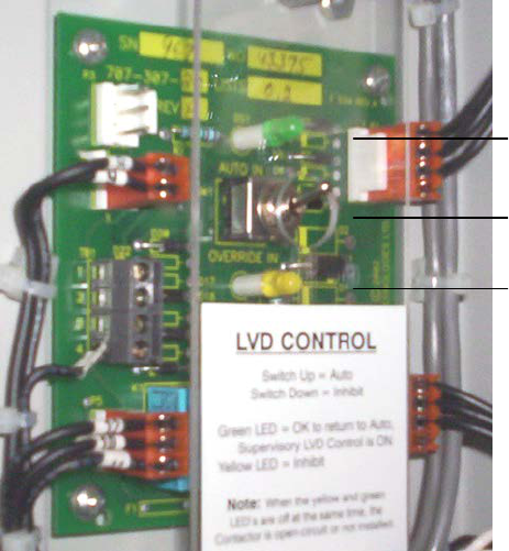
Figure 4–LVD control card option
The LVD Control functions can be hardwired directly from the assigned relay output to an optional LVD override
control and distribution alarm card (shown above).
Place the LVD Control switch to the OVERRIDE IN position to keep the LVD contactor engaged.
To remove a module, loosen the screw on the bottom of the faceplate. Slide the module away from the rear
connectors and out of the shelf.
Insert the replacement controller (as described above). The front-panel LED’s will illuminate temporarily, but will
extinguish after the system has finished its 15 second self-test.
WARNING
Do not leave the switch in the OVERRIDE IN position. Doing so may result in a complete discharge
of the batteries during a power failure situation.
To allow the CXCM4 to resume automatic control of the LVD contactor, return the LVD Control switch to the
AUTO IN position.
OVERRIDE IN or Inhibit
(amber) LED
LVD control switch
AUTO IN (green) LED

030-803-J0 Rev B Page 13 of 26
6 Wiring and Connections
This chapter provides cabling details and notes on cable sizing for DC applications with respect to the Alpha
Cordex 24-3.1kW modular switched mode rectifier system.
6.1 Safety Precautions
WARNING
Hazardous AC voltages may be present. Ensure power at the AC service panel is off before
attempting work on the AC connections. Use a voltmeter to verify the absence of voltage. Clearly
mark the correct polarity of the battery leads before commencing work on DC connections.
Refer to the previous (Installation) chapter for additional safety precautions.
6.2 Tools Required
Various tools are essential for product installation. Use this list as a guide:
• Philips head screwdriver, #1 (tip size 5/32”)
• Philips head screwdriver, #2 (tip size 3/16”)
• Slot head screwdriver (blade size 1/4”)
• Digital voltmeter equipped with test leads
• Adjustable 24Vdc load (optional)
• Cutters and wire strippers (#10 to #22AWG) (6 to 0.34mm
2
)
• Crimping tool (optional for large gauge wire)
• Socket and rachet set (Imperial measure)
• Anti-static wrist strap
• Computer (laptop) with Microsoft Internet Explorer 6 or greater
• Crossover cable RJ-45 (for access using the Ethernet port).
6.3 Power System Chassis Ground and DC Ground Reference
WARNING
For safety reasons, ensure the system is properly bonded to the building’s ground grid.
Both the shelf chassis ground (via power system chassis ground) and common return shall be connected to the
site ground to ensure correct operation of the system and to prevent drifting floating analog (especially current)
readings.
6.4 AC Feeder Protection/Sizing
To maximize system reliability, each power module should be fed from a dedicated protection feeder breaker
located at the AC distribution panel. The feeder breaker can also act as the disconnect device for the connected
module. Refer to the specifications at the front of this manual for Alpha recommendations.
6.5 AC Input Connections
WARNING
Use care when removing or replacing the covers for the AC input connections. Never assume that
an electrical connection or conductor is not energized.
CAUTION: AC input wires should be routed in flexible or rigid conduit as far away as possible
from the DC power wires to minimize EMI disturbances.
Ensure all modules are removed from the shelf.
The wireway is designed for two customer-supplied 1” conduit fittings for AC supply located one on each side of
the shelf. Attach the conduit retainers to the wireway hole(s) and route the AC cables through. Secure the wires to
the AC input and chassis ground terminals as required (see below). Tighten the cable connector to the AC cable
(conduit similar).

030-803-J0 Rev B Page 14 of 26
Replace rear cover(s) once all connections have been completed.
6.5.1 Single Phase
Remove the metal covers (2 places) from the rear of the shelf to expose the AC input terminal blocks, L1 and L2
for each rectifier. Each terminal pair relates to an individual power module as marked.
6.5.2 Dual Three Phase (23” shelf only)
Remove the metal covers (2 places) from the rear of the shelf to expose the AC input terminal blocks, L1, 2 and 3
for each rectifier grouping. N (for neutral) will also be used for the option selected when a Wye source is provided.
6.6 Calculating Output Wire Size Requirements
Wire size is calculated by first determining the appropriate maximum voltage drop requirement. Using the formula
below calculate the CMA wire size requirement. Determine the size and number of conductors required to satisfy
the CMA requirement.
CMA = (A x LF x K) / AVD, where:
CMA = Cross section of wire in circular MIL area
A = Ultimate drain in amps
LF = Conductor loop feet
K = 11.1 constant factor for commercial (TW type) copper wire
AVD = Allowable voltage drop
Check again that the ampacity rating of the cable meets the requirement for the installation application. Consult
local electrical codes (NEC, CEC, etc.) for guidelines. If required, increase the size of the cable to meet the code.
6.7 DC Output Connections
WARNING
Leave cables or bus bars disconnected at battery and verify output polarity using a voltmeter.
Make battery connections only after all other wiring is completed.
DC output wire shall be UL approved XHHW or RHH/RHW (for Canadian users, RW90 Type). Control and sense
wires shall be UL approved Style 1015 (for Canadian users, TEW type).
The common output leg of the rectifier system should be connected to ground. This is typically done at the load
common termination point.
6.7.1 Cable
Terminate cable leads with appropriate crimp lugs for 3/8” holes on 1” centers.
Secure the positive and negative to the shelf output post of the correct polarity; i.e., +Vcable to +Vpost. Ensure
the washers are on the bolts in the same order in which they were shipped from the factory. Tighten the bolts as
per Customer Connections drawing at the rear of this manual.
6.7.2 Bus Bar
Bus bar adapters may be factory-installed, for the option selected, to easily accommodate direct connections to
customers’ vertical bus bars.
Secure the positive and negative to the shelf output post of the correct polarity; i.e., +Vcable to +Vpost. Ensure
the washers are on the bolts in the same order in which they were shipped from the factory. Tighten the bolts as
per Customer Connections drawing at the rear of this manual.

030-803-J0 Rev B Page 15 of 26
6.8 CAN Serial Ports
Two CAN Serial ports (modular jacks with offset latches), are provided for communications with Alpha’s Cordex
rectifiers and other CAN-enabled equipment. These are located on the left side of the shelf (as viewed from the
front).
Daisy-chain from shelf to shelf (CAN OUT of one shelf to CAN IN of another) as necessary and ensure that only
the last shelf is terminated. See Figure 5.
6.8.1 CAN Termination
A jumper (or switch depending on your configuration) allows setting of the CAN OUT to be open (to the next shelf
in the system) or terminated. Termination must be enabled in final shelf on the CAN bus only. Access termination
selection (inside the shelf) by removing the leftmost rectifier #1 (MDL 1).
Figure 5–CAN serial ports and termination selection

030-803-J0 Rev B Page 16 of 26
6.9 Network Connection and Remote Communications via CXC
The Cordex system can be set up, monitored and tested via ETHERNET 10/100 Base-T serial data connection.
The communication protocol supports a web interface.
NOTE: Pinouts are shown in customer connections drawing for CXCM4.
Some standard scenarios are described below:
6.9.1 Ethernet Port for Network Connection (Standard Network Cable)
The Ethernet port is designed for CXC connection to a user supplied network (TCP/IP secured by user) via a front
panel RJ-45 jack. Connect to the Cordex shelf using a standard network cable.
6.9.2 Ethernet Port for Local Connection (Crossover Cable)
Local access (e.g. laptop computer) is also possible from the Ethernet port connection using a standard network
crossover cable.
6.9.3 CXC RS-232 Serial (Craft) Port for Local Connection
Local access to the CXC (CXCM4 or CXCP or CXCR) is possible through the front panel RS-232 serial port using
a null modem cable:
Figure 6–Null modem pinouts
030-803-J0 Rev B Page 17 of 26
6.10 Signal Wiring Connections for CXCM4
The CXCM4 (specifications 018-586-B1) requires an adapter for modular installation (drawing 747-275-08).
NOTE: To aid the user with installation, frequent reference is made to drawings located at the rear of this manual.
Custom configurations may be detailed within the Alpha power system documentation package.
For terminal block connections, the recommended wire sizes are 0.823 to 0.129mm
2
(#18 to #26 AWG) for the
temperature range of 0 to 50 deg. C (as per UL/CSA).
CAUTION: to reduce risk of fire, use only 0.129mm
2
(#26 AWG) or larger wire.
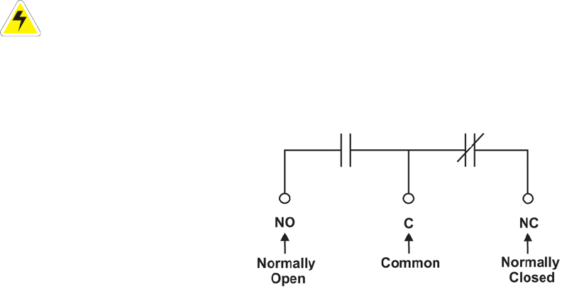
6.10.1 Alarm (Relay) Outputs
Terminals provide contacts for extending various alarm or control signals. Each relay output can be wired for NO
or NC operation during an alarm or control condition. See Figure 7.
Figure 7–Showing relay connections
Relays can be programmed to energize or de-energize during an alarm condition (see CXC Software manual).
When the CXCM4 reset button is pressed or power is lost, all relays de-energize.
System Fail output relay (K0) is fail-safe and will de-energize during an alarm condition.
6.10.1.1 LVD Control (External Option)
The LVD Control functions can be hardwired directly from the assigned relay output to an
optional LVD override control and distribution alarm card. This provides a safety measure to
protect against load disconnect during CXCM4 reset or replacement (see Section 5.4); e.g.
when the controller is off-line. Operators may also perform test and maintenance procedures on
the CXCM4 without disturbing the load.
6.10.2 Digital Inputs for CXC
The digital input channels (factory-installed) are used to monitor various alarm and control signals. All input
channels are voltage activated and accept a bipolar (i.e. negative or positive) DC signal directly.
6.10.2.1 Connection Method
Typical Alpha systems use the “reset with Hot and trigger with Ground” connection. The digital
input is wired in such a way that the Hot is wired directly into one of the input terminals; e.g.,
positive input for +24V systems. The other input terminal is wired to the Ground (common) of
the system through a relay (dry contact – usually located on the equipment requiring
monitoring). This method (see Figure 8) allows the digital input to receive (or not receive) a
Ground signal on an alarm.

030-803-J0 Rev B Page 18 of 26
Figure 8–Showing digital input connection method
6.10.2.2 Programming the Digital Input
The digital input channels can be programmed for “active high” or “active low.” Active high
indicates “alarm on the presence of a ground signal” and active low indicates “alarm on the
removal of a ground signal.” See CXC Software manual for detailed instruction on
programming.
Voltage Range (VDC)
Voltage Level (VDC)
Considered As “0” (Off)
Voltage Level (VDC)
Considered As “1” (On)
0—60
(system voltage setting)
0—3 18—60
Table A–Voltage level definitions for digital inputs
6.10.3 Analog Inputs
CAUTION: Ensure the correct polarity is used for all input cable terminations.
The analog input channels are used to monitor various types of electrical signals. Some of the analog channels
are reserved for specific signals, while others are designated as general-purpose inputs, which accommodate
various types of analog signals.
The Battery +24V should be connected at the battery system voltage terminal for CXC reference when a battery
disconnect device is used. It is critical to CXC operation as it ensures a source of power to the CXC should the
disconnect device open the circuit.
6.10.3.1 Voltage
Voltage Input #1 (load voltage per CXC software) terminals (V1) on the shelf provide
connections to an optional secondary voltage input. For example, this can be terminated to the
load side of an LVD contactor to monitor load voltage.
Voltage Input #2 (battery voltage per CXC software) is wired internally (V2) to the rectifier output
voltage of the shelf. This is used as the reference for system alarming (such as high voltage)
and control (such as low voltage disconnect).
6.10.3.2 Temperature Sensor
Temperature Probe input channels provide connections for temperature sensors. A voltage is
supplied to these terminals for sensor measurements.
6.10.3.3 Current
Current Input #1 (discharge or load current per CXC software) terminals (I1) are available for
customer connection as required.
Current Input #2 (charge or battery current per CXC software) terminals (I2) are available for
customer connection as required.
030-803-J0 Rev B Page 19 of 26
7 Operation
7.1 Main Rectifier States
Rectifier operation can be broken up into five main states:
1. Off,
2. Start delay,
3. Soft start,
4. Normal operation,
5. Turning off.
Each state is characterized as being distinct and necessary for the operation of the rectifier. These states are
briefly described below.
7.1.1 Off State
The rectifier will be in the Off state immediately after power is applied to the rectifier or after a rectifier shutdown.
The shutdown source may be remote or local shutdown, AC shutdown, OVP or thermal shutdown.
When the rectifier is in this state the DC-DC converter is turned off and the CXC will be monitoring its inputs for
the proper conditions to begin the start up sequence.
When the conditions have been met for the rectifier to start up, it will transition to the Start Delay state.
7.1.2 Start Delay State
When the rectifier is in the Start Delay state, the DC-DC converter is held off and still not sourcing power and is
waiting for a given amount of time before transitioning to the next state.
When in this state, the CXC continues to monitor its inputs.
After the Start Delay state the rectifier will transition to the Soft Start state.
NOTE: Soft start, or current walk-in, gradually increases the voltage and current output of the rectifier upon startup. This
is done to reduce the instantaneous load on the AC source.
7.1.3 Soft Start State
When the Soft Start state is entered, the rectifier will be turned on and the output voltage and output current will
be gradually increased. If a load is present, the rectifier will begin to source power.
When the voltage and current limit ramps have finished, the rectifier will transition to the Normal Operation state.
7.1.4 Normal Operation State
The Normal Operation state is the state that the rectifier will be in performing all of the rectifier functions and
features specified herein.
From this state, the only valid transition is to the Turning Off state. This transition will happen if the rectifier is
required to shut down.
7.1.5 Turning Off State
The Turning Off state is entered because a short delay is required before the rectifier actually turns off to take
care of any initialization requirements.
When this short delay has elapsed, a transition to the Off state is made.

030-803-J0 Rev B Page 20 of 26
7.2 Main Rectifier Modes
In addition to Main Rectifier States, there is a set of Main Rectifier Modes. These modes can be divided into two
categories as follows:
7.2.1 Output Voltage Modes
Voltage modes can be thought of as modes that, under software control, can directly adjust the output voltage.
The qualification of ‘under software control’ is made because there are processes that occur in the rectifier that
can change the output voltage that do not adjust the output voltage directly (such as the rectifier being in current
limit).
The following table lists the five Output Voltage Modes and a description of when they are active:
Output Voltage Modes
Active when…
Float
Output voltage is set to the float voltage setting.
Equalize
Output voltage is set to the equalize voltage setting.
Battery Test
Output voltage is set to the battery test voltage setting.
Safe
Output voltage is set to the safe mode voltage setting.
Manual Test
Output voltage can be manually adjusted outside of the standard adjustment ranges.
Table B–Output voltage modes
7.2.2 Output Current/Power Modes
These modes directly affect the output current and power.
The following table lists the four Output Current/Power Modes and a description of when they are active:
Output Current/Power Mode
Active when…
Temperature foldback mode
Output current and power limit have been reduced due to high temperature of the
heatsink or internal ambient temperature sensor.
AC foldback mode
Output current and power limit have been reduced due to low AC input voltage. Note:
this will reduce the risk of tripping an AC breaker due to increased AC current draw as
the AC voltage decreases.
Short circuit foldback mode
Output current limit has been reduced due to a short circuit at the output.
Internal fault foldback mode
Output current limit has been reduced due to an internal fault.
Table C–Output current/power modes
7.3 Can Bus Communications
The CAN bus is used for communication between the rectifier and CXC.
The communication between the rectifier and CXC consists of commands and data transfer that are used during
the operation of the power system to configure the rectifier with system settings and to monitor rectifier status.

030-803-J0 Rev B Page 21 of 26
7.4 Factory Ranges and Defaults
The following table lists the rectifier settings/ranges/defaults; changes are made via the CXC:
Setting
Range (minimum to maximum)
Default
Float (FL) Voltage
23.75 – 29.1V
27V
Equalize (EQ) Voltage
24.9 – 30.1V
27.5V
Battery Test (BT) Voltage
22 – 26V
23V
OVP
See note below – 31.5V
28.5V
Current Limit (CL)
23 – 100%
100%
Power Limit (PL)
0 – 100%
100%
Module Start Delay
0 – 250s
1s
System Start Delay
0 – 600s
0s
Low Voltage Alarm (LVA)
21 – 26V
22V
High Voltage Alarm (HVA)
26 – 31.5V
27.75V
EQ Timeout
1 – 2399h
30h
BT Timeout
1 – 250h
8h
Softstart Ramp-rate
Normal/Fast
Normal
CL/PL Alarm
Enable/Disable
Enable
Remote Shutdown
Enable/Disable
Enable
Ramp Test
Enable/Disable
Enable
Table D–Cordex 24-3.1kW factory ranges and defaults
NOTE: OVP cannot be set below the present system/FL/EQ/BT voltage setting or the safe mode voltage of 25.7V.
030-803-J0 Rev B Page 22 of 26
8 System Startup
After completing the shelf wiring and installation, perform the following startup and test procedure to ensure
proper operation:
8.1 Check System Connections
• Ensure AC is off, battery is disconnected, and all power modules are removed from the shelf.
• Triple check the polarity of all connections.
8.2 Verify AC and Power the Shelf
• Install one power module.
• Verify AC input voltage is correct and turn on the corresponding AC input feeder breaker.
• The power module OK LED should illuminate after a preset start delay.
• Using the CXC, test functionality of various module alarms and controls.
8.3 Check Battery Polarity and Connect
• Verify correct battery polarity using a voltmeter (ensuring no cells or batteries are reversed).
• Connect battery as required to the output of the system or turn on battery breaker.
• Install remaining power modules.
• In the adjustments menu of the CXC, set Float and Equalize voltage to the levels specified by the battery
manufacturer.
• Using the CXC, test functionality of various module alarms and controls. In addition, perform a load test with
the system using a resistive load box as needed.
8.4 CXC Reset
The reset button located on the front panel of the optional CXC is for restarting the microprocessor. When
pressed momentarily, the unit beeps twice then resets. The front-panel LED’s will illuminate temporarily, but will
extinguish after the system has finished its 15-second self-test.

030-803-J0 Rev B Page 23 of 26
9 Maintenance
Although very little maintenance is required with Alpha systems, routine checks and adjustments are
recommended to ensure optimum system performance. Qualified service personnel should do repairs.
The following table lists a few maintenance procedures for this system. These procedures should be performed at
least once a year.
WARNING: HIGH VOLTAGE AND SHOCK HAZARD.
Use extreme care when working inside the shelf while the system is energized.
Do not make contact with live components or parts.
Circuit cards, including RAM chips, can be damaged by static electricity. Always wear a grounded
wrist strap when handling or installing circuit cards.
Procedure
Date Completed
Clean ventilation openings
Inspect all system connections (re-torque as necessary)
Verify alarm/control settings
Verify alarm relay operation
Table E–Sample maintenance log
Rectifiers could fail due to lack of maintenance, specifically dirty filters if used. Initially filters should be checked
frequently until a proper maintenance schedule is developed to suit site conditions.
IMPORTANT
It is recommended that filter maintenance be promptly scheduled, to eliminate failure possibilities.
To access the filter for replacement (every 2 to 6 months), see fan replacement procedure that follows.
9.1 Fan or Filter Replacement
Figure 9–Fan (or filter) replacement

030-803-J0 Rev B Page 24 of 26
1. Shut off the unit and unscrew the front fastener that secures the power module to the shelf.
2. Slide the module 10 cm (4”) out of the shelf and wait two minutes for module capacitors to discharge.
3. Remove the four screws (two each side) that secure the front panel to the module chassis.
4. Slide the front panel out.
5. Disconnect the fan power lead wires (one set per fan) and front panel ribbon cable from the module.
6. Remove the screws that secure the fans to the front panel.
7. Note the direction of airflow and remove the fans (or filters) from the front panel.
8. Install the replacement fans (or filters) following the preceding steps in reverse order.
9.2 MOV Replacement
Figure 10–MOV replacement
The MOVs (metal oxide varistor) are used to protect the power modules from power line surges and the surges
caused by lightning strikes. High capacity surges may permanently damage MOVs but they are easily replaced in
the field using the following procedure:
1. Shut off the unit and unscrew the front fastener that secures the power module to the shelf.
2. Slide the module 10 cm (4”) out of the shelf and wait two minutes for module capacitors to discharge.
3. Turn the module around to face the back of the unit and remove the one screw (module bottom toward the
rear) securing the MOV cover.
4. Remove the cover and locate the MOV printed circuit board (PCB).
5. Remove the three screws that secure the MOV PCB.
6. Decontaminate the area and unit with flux remover or a similar cleaning compound. This is to remove any
metallic particles or carbon, which may have been deposited when the MOV failed.
7. Install the replacement MOV PCB following the preceding steps in reverse order.
See Section 1.3. The information is valid at the time of publication. Consult factory for up-to-date ordering information.

030-803-J0 Rev B Page 25 of 26
10 Warranty
Visit http://www.alpha.ca/web2/services-and-support/warranty.html for full warranty information.
10.1 Warranty
Alpha Technologies Ltd. warrants all equipment manufactured by it to be free from defects in parts and labor, for
a period of two years from the date of shipment from the factory. The warranty provides for repairing, replacing or
issuing credit (at Alpha’s discretion) for any equipment manufactured by it and returned by the customer to the
factory or other authorized location during the warranty period. There are limitations to this warranty coverage.
The warranty does not provide to the customer or other parties any remedies other than the above. It does not
provide coverage for any loss of profits, loss of use, costs for removal or installation of defective equipment,
damages or consequential damages based upon equipment failure during or after the warranty period. No other
obligations are expressed or implied. Warranty also does not cover damage or equipment failure due to cause(s)
external to the unit including, but not limited to, environmental conditions, water damage, power surges or any
other external influence.
The customer is responsible for all shipping and handling charges. Where products are covered under warranty
Alpha will pay the cost of shipping the repaired or replacement unit back to the customer.

030-803-J0 Rev B Page 26 of 26
11 Acronyms and Definitions
AC Alternating current
ANSI American National Standards Institute
AWG American Wire Gauge
BTU British thermal unit
CAN Controller area network
CEC Canadian Electrical Code
CSA Canadian Standards Association
CX Cordex™ series; e.g., CXC for Cordex System Controller
DC Direct current
DHCP Dynamic Host Configuration Protocol
EIA Electronic Industries Alliance
EMC Electromagnetic compatibility
EMI Electromagnetic interference
ERM Electromagnetic Compatibility and Radio Spectrum Matters
ESD Electrostatic Discharge
FCC Federal Communications Commission (for the USA)
HVSD High voltage shutdown
IEC International Electrotechnical Commission
IEEE Institute of Electrical and Electronics Engineers
IP Internet Protocol
LED Light emitting diode
LVD Low voltage disconnect
MOV Metal oxide varistor
MTBF Mean time between failures
NC Normally closed
NEC National Electrical Code (for the USA)
NO Normally open
OSHA Occupational Safety & Health Administration
OVP Over voltage protection
RAM Random access memory
RU Rack unit (1.75”)
TCP/IP Transmission Control Protocol / Internet Protocol
THD Total harmonic distortion
UL Underwriters Laboratories
Specifications for Alpha’s Switched Mode Rectifier Cordex 24-3k1W
Alpha Technologies Ltd. 010-601-B1 Rev B
Printed in Canada. © 2012 Alpha Technologies Ltd. ALPHA and CORDEX are trademarks of Alpha Technologies Ltd. All Rights Reserved. Page 1 of 3
Power Module Output
Voltage: 21 to 29Vdc within rated limits
Current: 115A @ 27Vdc nominal (130A maximum @ 24V)
Maximum Power: 3100W continuous/module
Static Load Regulation: Better than ±0.5% for any load change within rated limits
Dynamic Load Regulation: Better than ±4% for 40% - 90% load step
(output shall recover to static limits within 30ms)
Static Line Regulation: Better than ±0.1% for any change in input voltage within rated limits
Hold-up Time: >10ms
Time Stability: ≤0.5% per year
Temperature Stability: <300ppm/°C over the operating range
Heat Dissipation: <1176 BTU per hour
Electrical Noise: <32dBrnC (voice band)
<20mVrms 10kHz to 10MHz (wideband)
<100mVp-p 10kHz to 100MHz
<1.0mV (psophometric)
Acoustic Noise: <60dBa @ 1m (3ft.) @ 30°C (86°F)
EMI: The unit meets requirements of EN55022 (see Standards for more EMC)
In accordance with FCC requirements, we provide the following statement as specified in the FCC guidelines for
conformance to Part 15, Class B:
NOTE: This equipment has been tested and found to comply with the limits for a Class B digital
device, pursuant to part 15 of the FCC Rules. These limits are designed to provide reasonable
protection against harmful interference in a residential installation. This equipment generates,
uses, and can radiate radio frequency energy and, if not installed and used in accordance with
the instructions, may cause harmful interference to radio communications. However, there is no
guarantee that interference will not occur in a particular installation. If this equipment does cause
harmful interference to radio or television reception, which can be determined by turning the
equipment off and on, the user is encouraged to try to correct the interference by one or more of
the following measures:
• Reorient or relocate the receiving antenna.
• Increase the separation between the equipment and receiver.
• Connect the equipment into an outlet on a circuit different from that to which the receiver is connected.
• Consult the dealer or an experienced radio/TV technician for help.
Any changes or modifications to this equipment not expressly described in this manual could void the FCC
compliance.
Specifications for Alpha’s Switched Mode Rectifier Cordex 24-3k1W Continued
Alpha Technologies Ltd. 010-601-B1 Rev B
Printed in Canada. © 2012 Alpha Technologies Ltd. ALPHA and CORDEX are trademarks of Alpha Technologies Ltd. All Rights Reserved. Page 2 of 3
Power Module Input
Voltage: 208, 220, 230, 240, 277Vac nominal
Operational Range: 176 to 312Vac
Extended Operation: Low: 176 to 90Vac (derated power)
Frequency: 45 to 66Hz
Current: 14.6A @ 240Vac
16.9A @ 208Vac
20.2A @ 176Vac (maximum)
Recommended Feeder Breaker
Single Phase: 30A, #10AWG
Three Phase: 50A, #6AWG delta connection
30A, #10AWG wye connection
Power Factor: >0.99 at nominal conditions and 50-100% load
Protection: 10kA-interrupting capacity fuses in active and neutral lines
Efficiency: >90% at nominal conditions and 50-100% load
Inrush Current: ≤full load steady state current
Start-up Ready Time: <5 seconds (excluding soft start)
Start-up Delay: ≤120 seconds (programmable)
Soft Start: ≤10 seconds (user adjustable, not including start-up)
Input Transient Suppression: Meets ANSI/IEEE C62.41 Category B3
Input Leakage Current: <3.5mA @ 265Vac 60Hz
Environmental
Operating Temperature: -40 to +75°C, power derated above 65°C (149°F)
(-40 to 167°F)
Storage Temperature: -40 to +85°C
(-40 to 185°F)
Humidity: 0 to 95% non-condensing
Elevation: -500m to 2800m; to 4000m with temperature derated to 40°C
(-1640 feet to 9186 feet; to 13124 feet with temperature derated to 104°F)
Miscellaneous
MTBF: >350,000 hours ground benign @ 30°C (86°F)
Dimensions: Refer to Outline drawings
Specifications for Alpha’s Switched Mode Rectifier Cordex 24-3k1W Continued
Alpha Technologies Ltd. 010-601-B1 Rev B
Printed in Canada. © 2012 Alpha Technologies Ltd. ALPHA and CORDEX are trademarks of Alpha Technologies Ltd. All Rights Reserved. Page 3 of 3
Weight: Module: 4.6 kg (10.1 lb.)
23” Shelf: 14.5 kg (32 lb.)
19” Shelf: 12.7 kg (28 lb.)
Safety
EN 60950 Rectifier output shall be rated SELV suitable for connection to TNV-1 circuits
UL 60950
CSA C22.2 No. 60950
CE EN 60950, CB Scheme
73/23/EEC Low Voltage Directive with amendment 93/68/EEC
Telcordia (Bellcore) GR-1089-CORE (requirements applicable to rectifier)
Other Referenced Standards
EN 300 386-2 EMC and ERM; Telecommunication Network Equipment
EN 55022 (CISPR 22) Information Technology Equipment – Radio Disturbance Characteristics – Limits
and Methods of Measurement
EN 61000-3-2 Harmonic Current Emissions
EN 61000-3-3 Voltage Fluctuations and Flicker
EN 61000-4-2 ESD Immunity
EN 61000-4-3 Radiated Electromagnetic Immunity
EN 61000-4-4 Electrical Fast Transient/Burst Immunity
EN 61000-4-5 Power Line Surge Immunity
EN 61000-4-6 Conducted Electromagnetic Immunity
EN 61000-4-11 Voltage Dips, Short Interruptions and Variations
ETS 300 019-1-1 Environmental Conditions; Storage
ETS 300 019-1-2 Environmental Conditions; Transportation
ETS 300 132-2 Power Supply Interface at the Input to Telecommunications Equipment; Operated
by Direct Current (DC)
ETS 300 753 Acoustic Noise Emissions
IEC 60950 Safety of Information Technology Equipment, Including Electrical Business
Equipment (UL/CSA 60950)
The above information is valid at the time of publication. Consult factory for up-to-date ordering information.
Specifications are subject to change without notice.
SPECIFICATIONS FOR ALPHA’S CXCM4 CORDEX CONTROLLER MODULAR 4RU MODEL
Alpha Technologies Ltd. 018-586-B1 Rev B
Printed in Canada. © 2012 Alpha Technologies Ltd. ALPHA and CORDEX are trademarks of Alpha Technologies Ltd. All Rights Reserved. Page 1 of 2
Basic Unit, CXCM4
Input Voltage: 17 to 65Vdc within rated limits
Current: <100mA @ 48Vdc
<200mA @ 24Vdc
MTBF: >430,000 hours @ 30°C (86°F)
EMC: The unit meets requirements of:
ICES-003 Class B
EN 55022 Class B (CISPR 22)
EN 61000-4-2 ESD
EN 61000-4-3 Radiated Immunity
EN 61000-4-4 EFT /Burst
EN 61000-4-6 Conducted Immunity
FCC Part 15 Class B, FCC Part 68
In accordance with FCC requirements, we provide the following statement as specified in the FCC guidelines for
conformance to Part 15, Class B:
NOTE: This equipment has been tested and found to comply with the limits for a Class B digital
device, pursuant to part 15 of the FCC Rules. These limits are designed to provide reasonable
protection against harmful interference in a residential installation. This equipment generates,
uses, and can radiate radio frequency energy and, if not installed and used in accordance with
the instructions, may cause harmful interference to radio communications. However, there is no
guarantee that interference will not occur in a particular installation. If this equipment does cause
harmful interference to radio or television reception, which can be determined by turning the
equipment off and on, the user is encouraged to try to correct the interference by one or more of
the following measures:
• Reorient or relocate the receiving antenna.
• Increase the separation between the equipment and receiver.
• Connect the equipment into an outlet on a circuit different from that
to which the receiver is connected.
• Consult the dealer or an experienced radio/TV technician for help.
Any changes or modifications to this equipment not expressly described in this manual could void the FCC
compliance.
Environmental
Temperature: -40 to 65°C standard @ 3000m derate to 55°C @ 4000m
(-40 to 149°F derate to 131°F @ 13124ft)
Humidity: 0 to 95% non-condensing
Elevation: -500 to +4000m
(-1640 to 13124 ft)
SPECIFICATIONS FOR ALPHA’S CXCM4 CORDEX CONTROLLER MODULAR 4RU MODEL CONTINUED
Alpha Technologies Ltd. 018-586-B1 Rev B
Printed in Canada. © 2012 Alpha Technologies Ltd. ALPHA and CORDEX are trademarks of Alpha Technologies Ltd. All Rights Reserved. Page 2 of 2
Hardware Specifications, CXCM4
CPU: Coldfire
RAM: 8MB
Flash: 4MB standard, 8MB optional
Display: 160 x 160 pixel grayscale LCD
Front Panel Controls: Reset button and touch panel (display and input device)
LED’s: System OK (Green)
Power System Minor Alarm (Yellow)
Power System Major Alarm / Controller Fail (Red)
Audio: Built-in speaker for alarm and popup message tones
Dimensions: 177mm H x 74mm W x 255mm D
(6.9” H x 2.9” W x 10“ D)
Weight: 1.8 kg (3.9 lb.)
Mounting: Integrated on Cordex 4RU series 19” and 23” shelves
Communication Ports: Ethernet RJ-45, CAN [see shelf specifications]
Relay Outputs: Eight (8) Form C, 60Vdc 1A maximum
Digital Inputs: Four (4), 0 to 60Vdc
Analog Inputs
and System Signals: Two (2) DC voltage
-LVD1 (K1), Form C relay, 60Vdc 1A maximum
-Load Voltage (V1), 0 to 100Vdc
Two (2) current, ±50mV
Two (2) temperature, 0 to 20Vdc with power source
Additional Inputs, List 121: Two (2) temperature, 0 to 20Vdc with power source
Additional Inputs, List 125: Two (2) temperature, 0 to 20Vdc with power source
Two (2) bi-voltage, ±60V bi-polar voltage
Recommended Signal Wire Sizes (as per UL/CSA)
Minimum Wire Size: 0.129 to 0.823mm
2
(#26 to #18 AWG)
Temperature Range: 0 to 50°C
(32 to 122°F)
CAUTION – TO REDUCE RISK OF FIRE, USE ONLY 0.129mm
2
(#26 AWG) OR LARGER WIRE.
The above information is valid at the time of publication. Consult factory for up-to-date ordering information.
Specifications are subject to change without notice.

0
6.00 152.4
15.28 388.2
16.10 408.9
.88 22.3
1.63 41.5
0
4.92 125
5.92 150.4
6.92 175.8
7.92 201.2
12.92 328.2
13.92 353.6
14.92 379
15.92 404.4
20.84 529.3
0
5.05 128.3
6.05 153.7
6.55 166.4
6.97 177
22.31 566.7
LIST 23
23" MID-MOUNT
LIST 25
23" FLUSH-MOUNT
TOP VIEW
(SHOWN WITH LIST 82 - OUTPUT BARS)
REAR VIEW
MODULES ARE HIDDEN
LIST 90
FRONT VIEW
MODULE BLANK
010-572-20
3.1kW CORDEX MODULE
.50 13 6.50 165
1.25 31.8
584.223.00
13.50
13.50
1.25 31.8
N.T.S.
SIZE DWG NO.TYPE
B
SHEET
TITLE
ISSUE
DATE
OF
TOLERANCES
SCALE
APPROVED
CHECKED
DRAWN
DESIGN
MATERIAL
FINISH
FOR MANUFACTURING WITHOUT ITS WRITTEN CONSENT.
ARGUS TECHNOLOGIES AND SHALL NOT BE COPIED OR USED
THESE DESIGNS AND SPECIFICATIONS ARE THE PROPERTY OF
REVISIONS
LTR DESCRIPTION APPDDATE
REV
2005/
2005/
DIMENSIONS ARE IN INCHES WITH METRIC (mm) IN BRACKETS: INCHES [mm]
0.01"X.XXX
0.02"X.XX
0.04"X.X
0.25mm
030-736-06
[X.XX]
24V - 3.1kW, CORDEX
OUTLINE, 23" SHELF
Doc. 070-024-83
PER P.O. and
0.5mm
2
WH/EOF
J.U.
2004/05
2005/01
D2
c 2005 ARGUS TECHNOLOGIES
O
A
[X] 1mm
[X.X]
1
REV BY
REAR ISOMETRIC VIEW

LIST 89 - KYDEX REAR COVER
TOP VIEW
(SHOWN WITH LIST 82 - OUTPUT BARS)
17.17 436
REAR ISOMETRIC VIEW
SIZE DWG NO.TYPE
B
SHEET
TITLE
ISSUE
DATE
OF
SCALE
REV
030-736-06
OUTLINE, 23" SHELF
24V - 3.1kW, CORDEX
22
WH/EOF
D2
c 2005 ARGUS TECHNOLOGIES
O
A
DIMENSIONS ARE IN INCHES WITH METRIC (mm) IN BRACKETS: INCHES [mm]
N.T.S.
FOR MANUFACTURING WITHOUT ITS WRITTEN CONSENT.
THESE DESIGNS AND SPECIFICATIONS ARE THE PROPERTY OF
ARGUS TECHNOLOGIES AND SHALL NOT BE COPIED OR USED
SIDE VIEW

18.31 465.1
16.10 408.9
0
0
23.6.93
388.215.28
17.40 441.9
0
12.11 307.6
166.46.55
177.06.97
129.75.11
0
131.35.17
150.35.92
175.76.92
194.87.67
244.19.61
263.110.36
288.511.36
6.11 155.1
17.40 441.9
SIZE
DWG NO.
TYPE
B
SHEET
TITLE
ISSUE
DATE
OF
TOLERANCES
SCALE
APPROVED
CHECKED
DRAWN
DESIGN
MATERIAL
FINISH
FOR MANUFACTURING WITHOUT ITS WRITTEN CONSENT.
ARGUS TECHNOLOGIES AND SHALL NOT BE COPIED OR USED
THESE DESIGNS AND SPECIFICATIONS ARE THE PROPERTY OF
REVISIONS
LTR DESCRIPTION
APPDDATE
REV
X.X
0.04"
X.XX
0.02"
X.XXX
0.01"
[X]
1mm
[X.X]
0.5mm
[X.XX] 0.25mm
030-737-06
OUTLINE, 19" SHELF
24V - 3.1kW, CORDEX
PER P.O. and
Doc. 070-024-83
1 2
WH/EOF
J.U.
2004/05
2005/01
D2
c 2005 ARGUS TECHNOLOGIES
O
B
DIMENSIONS ARE IN INCHES WITH METRIC (mm) IN BRACKETS: INCHES [mm]
G.S. 2005/01
N.T.S.
REV BY
B ADDED MID-MOUNT OPTIONS S.D.W. 2007/01 SS
010-572-10
3.1kW MODULE
FRONT VIEW
LIST 90
MODULE BLANK
.50
19.0
12.7
482.8
44.51.75
1.75 44.5
TOP VIEW
REAR VIEW
LIST 89
KYDEX COVER
REAR VIEW
MODULES ARE HIDDEN

17.16 436.0
0
127.75.03
.93 23.6
6.97
171.1
6.74
0
177.0
37.71.49
6.0.24
139.35.49
22.31 566.7
171.1
0
6.74
6.0.24
37.71.49
94.93.74
139.35.49
177.06.97
82.23.24
50.41.99
126.64.99
18.31 465.1
TOP VIEW - LIST 19 - 19" MID MOUNT
FRONT VIEW - LIST 23 - 23" MID MOUNT
23.06 585.7
LIST 23
23" CABINET MID MOUNT
SIZE
DWG NO.
TYPE
B
SHEET
TITLE
ISSUE
DATE
OF
SCALE
REV
030-737-06
OUTLINE, 19" SHELF
24V - 3.1kW, CORDEX
2 2
D2
c 2005 ARGUS TECHNOLOGIES
O
B
DIMENSIONS ARE IN INCHES WITH METRIC (mm) IN BRACKETS: INCHES [mm]
N.T.S.
FOR MANUFACTURING WITHOUT ITS WRITTEN CONSENT.
THESE DESIGNS AND SPECIFICATIONS ARE THE PROPERTY OF
ARGUS TECHNOLOGIES AND SHALL NOT BE COPIED OR USED
FRONT VIEW - LIST 19 - 19" MID MOUNT
19.40 492.7
19.01 482.8

GND
J8
J7
1.
PIN OUT (J8)
CAN OUT RJ12 OFFSET
PIN OUT (J7)
CAN IN RJ12 OFFSET
CAN H2.
NOT CONNECTED3.
CAN L4.
NOT CONNECTED5.
NOT CONNECTED6.
GND1.
CAN H2.
NOT CONNECTED3.
CAN L4.
NOT CONNECTED5.
NOT CONNECTED6.
N
L1
L2
L3
N
N
CONNECT NEUTRAL TO ANY
ONE OF THE THREE
TERMINAL BLOCK POSITIONS
LABELED 'N'
DETAIL 'A' - AC INPUT OPTIONS
REAR VIEW - AC BACK COVER REMOVED
BLANK PLATE
TERMINAL
CONDUIT FITTING
CUSTOMER SUPPLIED 1"
1.3 [34] HOLE FOR
2 PLACES
AC WIREWAY (2 PLACES)
PROTECTIVE EARTH
AC WIREWAY
SEE DETAIL 'A'
L2
L1
L1
L1
L2
L2
N
N
WYE SOURCE, NEUTRAL REQUIRED
L3
L2
L1
LIST 84 - DUAL 3-PHASE INPUTS, 360 - 480 VAC,
N
CAN
SWITCH SETTING FOR CAN TERMINATION
UNTERMINATED
CAN
TERMINATED
L2
L1
L3
L1
L3
L2
LIST 83: DUAL 3-PHASE INPUTS, 208 - 240VAC
NO NEUTRAL
L2
LIST 85 - SINGLE PHASE INPUTS, 208V - 277VAC
L1
L1
L1
L2
L2
N.T.S.
SIZE DWG NO.TYPE
B
SHEET
TITLE
ISSUE
DATE
OF
TOLERANCES
SCALE
APPROVED
CHECKED
DRAWN
DESIGN
MATERIAL
FINISH
FOR MANUFACTURING WITHOUT ITS WRITTEN CONSENT.
ARGUS TECHNOLOGIES AND SHALL NOT BE COPIED OR USED
THESE DESIGNS AND SPECIFICATIONS ARE THE PROPERTY OF
REVISIONS
LTR DESCRIPTION APPDDATE
REV
2005/
2005/
DIMENSIONS ARE IN INCHES WITH METRIC (mm) IN BRACKETS: INCHES [mm]
0.01"X.XXX
0.02"X.XX
0.04"X.X
0.25mm
030-736-08
[X.XX]
23" SHELF, 3.1kW CORDEX
CUSTOMER CONNECTION
Doc. 070-024-83
PER P.O. and
0.5mm
2
WH
J.U.
2004/05
2005/02
D2
c 2005 ARGUS TECHNOLOGIES
O
A
[X] 1mm
[X.X]
1
REV BY

REAR ISOMETRIC VIEW - DC CABLE INSTALLATION
NEGATIVE (-)
OUTPUT TERMINAL
POSITIVE (+)
OUTPUT TERMINAL
3/8" FLAT WASHER
3/8-20 HEX BOLT
3/8" 2 HOLE COMPRESSION TERMINAL
1" SPACING (CUSTOMER SUPPLIED)
DC WIRING
(CUSTOMER
SUPPLIED)
REAR COVER
LIST 89
3/8" FLAT WASHER
3/8" LOCK WASHER
3/8-20 NUT
POSITIVE (+) BUS BAR
(CUSTOMER SUPPLIED)
POSITIVE (+)
OUTPUT TERMINAL
NEGATIVE (-)
OUTPUT TERMINAL
NEGATIVE (-) BUS BAR
(CUSTOMER SUPPLIED)
3/8" FLAT WASHER
3/8"-20 HEX BOLT
REAR ISOMETRIC VIEW - BUS BAR INSTALLATION
3/8" FLAT WASHER
3/8" LOCK WASHER
3/8-20 NUT
REAR VIEW - DC CABLE INSTALLATION
REAR COVER NOT SHOWN
SIZE DWG NO.TYPE
B
SHEET
TITLE
ISSUE
DATE
OF
SCALE
MATERIAL: SEE SHEET 1
FOR MANUFACTURING WITHOUT ITS WRITTEN CONSENT.
ARGUS TECHNOLOGIES AND SHALL NOT BE COPIED OR USED
THESE DESIGNS AND SPECIFICATIONS ARE THE PROPERTY OF
REVISIONS
LTR DESCRIPTION APPDDATE
REV
030-736-08
CUSTOMER CONNECTION
23" SHELF, 3.1kW CORDEX
22
WH
J.U.
2004/05
2005/02
D2
c 2005 ARGUS TECHNOLOGIES
O
A
DIMENSIONS ARE IN INCHES WITH METRIC (mm) IN BRACKETS: INCHES [mm]
2005/
2005/
N.T.S.
REV BY

SWITCH SETTING FOR CAN TERMINATION
GND
J8
J7
1.
PIN OUT (J8)
CAN OUT RJ12 OFFSET
PIN OUT (J7)
CAN IN RJ12 OFFSET
CAN H2.
NOT CONNECTED3.
CAN L4.
NOT CONNECTED5.
NOT CONNECTED6.
GND1.
CAN H2.
NOT CONNECTED3.
CAN L4.
NOT CONNECTED5.
NOT CONNECTED6.
CONDUIT FITTING
REAR VIEW - AC REAR COVER REMOVED
SEE DETAIL 'A'
AC WIREWAY
PROTECTIVE EARTH
2 PLACES
TERMINAL
BLANK PLATE
AC WIREWAY (2 PLACES)
1.3 [34] HOLE FOR
CUSTOMER SUPPLIED 1"
DETAIL 'A' - AC INPUT
L1
L2
L2
L1
SINGLE PHASE INPUTS, 208V - 277VAC
L2
L1
L1
L1
L2
L2
CAN
TERMINATED
CAN
UNTERMINATED
N.T.S.
SIZE DWG NO.TYPE
B
SHEET
TITLE
ISSUE
DATE
OF
TOLERANCES
SCALE
APPROVED
CHECKED
DRAWN
DESIGN
MATERIAL
FINISH
FOR MANUFACTURING WITHOUT ITS WRITTEN CONSENT.
ARGUS TECHNOLOGIES AND SHALL NOT BE COPIED OR USED
THESE DESIGNS AND SPECIFICATIONS ARE THE PROPERTY OF
REVISIONS
LTR DESCRIPTION APPDDATE
REV
2005/
2005/
DIMENSIONS ARE IN INCHES WITH METRIC (mm) IN BRACKETS: INCHES [mm]
0.01"X.XXX
0.02"X.XX
0.04"X.X
0.25mm
030-737-08
[X.XX]
19" SHELF, 3.1kW CORDEX
CUSTOMER CONNECTION
Doc. 070-024-83
PER P.O. and
0.5mm
2
WH
J.U.
2004/05
2005/02
D2
c 2005 ARGUS TECHNOLOGIES
O
A
[X] 1mm
[X.X]
1
REV BY

POSITIVE (+)
OUTPUT TERMINAL
NEGATIVE (-)
OUTPUT TERMINAL
3/8" FLAT WASHER
3/8" LOCK WASHER
3/8-20 NUT
3/8" 2 HOLE COMPRESSION TERMINAL
1" SPACING (CUSTOMER SUPPLIED)
3/8" FLAT WASHER
3/8-20 x 1" HEX BOLT
DC WIRING
(CUSTOMER
SUPPLIED)
REAR COVER
LIST 89
REAR ISOMETRIC VIEW - DC CABLE INSTALLATION
REAR VIEW - DC CABLE INSTALLATION
REAR COVER NOT SHOWN
SIZE DWG NO.TYPE
B
SHEET
TITLE
ISSUE
DATE
OF
SCALE
REV
030-737-08
CUSTOMER CONNECTION
19" SHELF, 3.1kW CORDEX
22
WH
D2
c 2005 ARGUS TECHNOLOGIES
O
A
DIMENSIONS ARE IN INCHES WITH METRIC (mm) IN BRACKETS: INCHES [mm]
N.T.S.
FOR MANUFACTURING WITHOUT ITS WRITTEN CONSENT.
THESE DESIGNS AND SPECIFICATIONS ARE THE PROPERTY OF
ARGUS TECHNOLOGIES AND SHALL NOT BE COPIED OR USED
REAR ISOMETRIC VIEW - BUS BAR INSTALLATION
POSITIVE (+)
OUTPUT TERMINAL
NEGATIVE (-)
OUTPUT TERMINAL
NEGATIVE (-) BUS BAR
(CUSTOMER SUPPLIED)
POSITIVE (+) BUS BAR
(CUSTOMER SUPPLIED)
3/8" FLAT WASHER
3/8" LOCK WASHER
3/8-20 NUT
3/8" FLAT WASHER
3/8-20 x 1" HEX BOLT

SIZE
DWG NO.
TYPE
B
SHEET
TITLE
ISSUE
DATE
OF
TOLERANCES
SCALE
APPROVED
CHECKED
DRAWN
DESIGN
MATERIAL
FINISH
FOR MANUFACTURING WITHOUT ITS WRITTEN CONSENT.
ARGUS TECHNOLOGIES AND SHALL NOT BE COPIED OR USED
THESE DESIGNS AND SPECIFICATIONS ARE THE PROPERTY OF
REVISIONS
LTR DESCRIPTION
APPDDATE
REV
X.X 0.04"
X.XX 0.02"
X.XXX 0.01"
[X] 1mm
[X.X] 0.5mm
[X.XX] 0.25mm
018-574-08
CUSTOMER CONNECTION,
CORDEX CXCM4
PER P.O. and
Doc. 070-024-83
1 1
DGW
SDW
2005/05
2005/07
D2
c 2005 ARGUS TECHNOLOGIES
O
A
NTS
REV BY
1. NOT CONNECTED
2. RXD
3. TXD
4. NOT CONNECTED
5. GROUND
6. NOT CONNECTED
7. NOT CONNECTED
8. NOT CONNECTED
9. NOT CONNECTED
DB-9 PIN OUT
1
A1 B1
PIN
A32 B32
K1 - NO
K1 - NC
K2 - COM
K3 - NO
K3 - NC
K4 - COM
K5 - NO
K5 - NC
K6 - COM
K7 - NO
K7 - NC
K8 - COM
K0 - NO
K0 - NC
D4 - 1
D3 - 1
D2 - 1
D1 - 1
NOT CONNECTED
+15V DCCT
GP4 -
GP3 -
GP2 -
GP1 -
I1 -
I2 -
I3 -
I4 -
V1 -
V2 -
NOT CONNECTED
PWA -
K1 - COM
K2 - NO
K2 - NC
K3 - COM
K4 - NO
K4 - NC
K5 - COM
K6 - NO
K6 - NC
K7 - COM
K8 - NO
K8 - NC
K0 - COM
D4 - 2
D3 - 2
D2 - 2
D1 - 2
NOT CONNECTED
-15V DCCT
DGND
GP4 +
GP3 +
GP2 +
GP1 +
I1 +
I2 +
I3 +
I4 +
V1 +
V2 +
NOT CONNECTED
PWA +
64 PIN CONNECTOR
PIN OUT
RESET SWITCH
1. TX +
2. TX -
3. RX +
4. ECOM1
5. ECOM1
6. RX -
7. ECOM1
8. ECOM1
9. LED 2 - 1
10. LED 2 RIGHT
11. LED 1 - 1
12. LED 1 LEFT
13. LED 2 - 1
14. LED 1 - 1
15. COMMON
16. COMMON
ETHERNET RJ-45 PIN OUT
1
A1 B1
PIN
A16 B16
RS485 DIR
RS485 +
R1
CTS
RTS
BDSR
GROUND
CAN L1
CAN L2
DFSC2
E LED1 - 2
E LED2 - 2
NOT CONNECTED
E TX +
E TX -
E COM1
+5V
RS485 -
DTR
TXD
RXD
DCD
GROUND
CAN H1
CAN H2
SYSTEM FAIL
E LED1 - 1
E LED2 - 1
NOT CONNECTED
E RX +
E RX -
E COM 2
32 PIN CONNECTOR
PIN OUT

M3x10 PH SCREW, LOCK AND FLAT WASHERS
#6-32x0.375 PH SCREW, LOCK AND FLAT WASHERS
SHELF ON THE CAN BUS ONLY
SECURE ADAPTOR INTO SHELF MODULE #1 SLOT
CAN TERMINATION SWITCH
ENABLE TERMINATION IN THE FINAL
3.1kW CORDEX SHELF
747-275-20 ADAPTOR
T1 T2 T3 T4
21. K7-NO
16. K3-NC
1. K2-NO
25. K1-COM
CAN H
8. K6-NC
23. K8-COM
11. K8-NC
24. K0-NO
CXCM4
6. K5-COM
121
22. K7-NC
24. D4-2
18. K5.NO
4. K4-NO
T1 T2 BiV1 BiV2
-
CAN-RET
25. K0-NC
14. K2-COM
CXCM4
13. NOT CONNECTED
LIST OPTION
17. K4-COM
10. K8-NO
P4 PINOUT
9. K7-COM
22. D2-2
J9 PINOUT
2. K2-NC
23. D3-2
(DB25 MALE)
LIST 125
3. K3-COM
(DB25 FEMALE)
GP1 GP2 GP3 GP4
5. K4-NC
PINOUT
125
- POWER
19. K5-NC
4. I3
-
P5 PINOUT
7. K6-NO
+POWER
2. I4
12. K0-COM
21. D1-2
20. K6-COM
-
3. I3+
CAN L
15. K3-NO
1. V1+
2. I2+
3. I1+
4. GP1+
5. GP2+
6. GP3+
7. GP4+
8. D1-1
9. D2-1
10. D3-1
11. D4-1
12. K1-NO
13. K1-NC
14. V1-
15. I2-
16. I1-
17. GP1-
18. GP2-
19. GP3-
20. GP4
1. I4+
5.
6.
7.
17.
20.
ONLY REQUIRED WHEN USING
J4
E1
J9
P5
P4
BATTERY DISCONNECT DEVICE
BATTERY CONNECTION (+24V)
CXCM4 POWER AND RECTIFIER CAN
COMMUNICATIONS CONNECTOR
20
17
7
6
5
REV
747-275-08
Doc. 070-024-83
J.K.
1 1
2007/02
CXCM4 CONNECTION
D2
c 2006 ARGUS TECHNOLOGIES
O
JLM
2006/6
2007/02
SIZE
DWG NO.
TYPE
B
SHEET
TITLE
ISSUE
DATE
OF
TOLERANCES
SCALE
FOR MANUFACTURING WITHOUT ITS WRITTEN CONSENT.
INTERFACE, CXRF 24V SHELF
DATE
DESCRIPTION
N.T.S.
REVISIONS
LTR
APPD
DESIGN
0.01"X.XXX
0.02"
0.04"
APPROVED
A
2007/02
CHECKED
X.X
DRAWN
X.XX
ARGUS TECHNOLOGIES AND SHALL NOT BE COPIED OR USED
MATERIAL
0.25mm
FINISH
THESE DESIGNS AND SPECIFICATIONS ARE THE PROPERTY OF
[X] 1mm
[X.X]
0.5mm
[X.XX]
PER P.O. and
REV BY

Visit us at www.alpha.ca
Due to continuing product development, Alpha Technologies reserves the right to change specifications without notice.
Copyright © 2014 Alpha Technologies. All Rights Reserved. Alpha® is a registered trademark of Alpha Technologies.
Alpha Technologies Ltd.
7700 Riverfront Gate
Burnaby, BC V5J 5M4
Canada
Tel: +1 604 436 5900
Fax: +1 604 436 1233
Toll Free: +1 800 667 8743
Alpha Energy,
Alpha Technologies Inc.
3767 Alpha Way
Bellingham, WA 98226
United States
Tel: +1 360 647 2360
Fax: +1 360 671 4936
Alpha Industrial Power Inc.
1075 Satellite Blvd NW,
Suite 400
Suwanee, GA 30024
United States
Tel: +1 678 475 3995
Fax: +1 678 584 9259
Outback Power
5917 195th St NE,
Arlington, WA 98223
United States
Tel: +1 360 435 6030
Fax: +1 360 435 6019
Alpha Technologies GmbH
Hansastrasse 8
D-91126
Schwabach, Germany
Tel: +49 9122 79889 0
Fax: +49 9122 79889 21
Alpha Technologies S.A.
131 Boulevard de l’Europe
1301 Wavre
Belgium
Tel: +32 10 438 510
Fax: +32 10 438 213
Alpha Technologies Europe Ltd.
Twyford House Thorley
Bishop’s Stortford
Hertfordshire, CM22 7PA
United Kingdom
Tel: +44 1279 501110
Fax: +44 1279 659870
Alphatec Ltd.
339 St. Andrews St.
Suite 101 Andrea Chambers
P.O. Box 56468
3307 Limassol, Cyprus
Tel: +357 25 375 675
Fax: +357 25 359 595
Alpha TEK ooo
Khokhlovskiy Pereulok 16
Stroenie 1, Office 403
Moscow, 109028
Russia
Tel: +7 495 916 1854
Fax: +7 495 916 1349
Alpha Technologies
Suite 1903, 191F., Tower 1,
33 Canton Rd. Tsim Sha Tsui
China, Hong Kong City,
Kowloon, Hong Kong
Tel: +852 2736 8663
Fax: +852 2199 7988
Alpha Innovations Brasil
Rua Manuel Augusto
de Alvarenga, 155
São Paulo, SP - Brasil
Tel: +55 11 2476 0150
Fax: +55 11 2476 0150
Alphatec Baltic
S. Konarskio Street 49-201
Vilnius, LT-03123
Lithuania
Tel: +370 5 210 5291
Fax: +370 5 210 5292
For technical support, contact Alpha Technologies:
Canada and USA: 1-888-462-7487
International: +1-604-436-5547
