
MXA920
Ceiling Array Microphone
User guide for Shure MXA920 ceiling array microphones. Learn how to install square and round mics, set up coverage, and quickly get great
sound in any room.
Version: 1.3 (2024-H)

Shure Incorporated
2/54
Table of Contents
MXA920 Ceiling Array Microphone 4
New in Firmware 6.2 4
Getting Started 4
Designer Setup Example 4
Web Application Setup Example 6
MXA920 Parts 7
Power Over Ethernet (PoE) 9
Model Variations 9
Optional Accessories and Replacement Parts 9
MXA920 Codec Certifications 9
What's in the Box 9
Reset Button 10
Reset Modes 10
MXA920 Control Software 10
Control Devices with Shure Designer Software 11
Open the Web Application with HTTPS 11
Firmware Updates 11
Use Designer's Auto Route 11
Mute Sync 12
MXA920 Coverage 13
Add Coverage Areas 14
Remove Unwanted Sounds with the Virtual Acoustic
Boundary 16
Use Steerable Lobes 17
Adjust Levels 17
How to Install the MXA920 17
Installing in a Ceiling Grid 19
VESA Standardized Mounting 22
Suspending from the Ceiling 22
Install on a Ceiling with the A900-CM 22
Hard Ceiling Mounting 23
Dante Channels 23
IntelliMix DSP 23
DSP Best Practices 23
Acoustic Echo Cancellation 23
Noise Reduction 25
Automatic Gain Control (AGC) 25
Delay 25
Compressor 25
Parametric Equalizer 26
Automix 28
Automix Channel 28
Automix Settings 28
Speech Gating Threshold and Enhanced Noise Filtering 3
0
Automix Modes 31
Encryption 32
Set Up the 802.1X Protocol for a Device 32
Turn Off or Clear 802.1X Settings 33
Change 802.1X Settings 33
Troubleshooting 802.1X Setup Issues 33
Networking Best Practices 34
Switch and Cable Recommendations for Dante Network
ing 34
Device IP Configuration 34
Setting Latency 35
QoS (Quality of Service) Settings 35
IP Ports and Protocols 36

Shure Incorporated
3/54
Digital Audio Networking 36
Compatibility with Dante Domain Manager 37
Dante Flows for Shure Devices 37
AES67 38
Sending Audio from a Shure Device 38
Receiving Audio from a Device Using a Different Audio
Network Protocol 38
Paint the MXA920 38
Paint Square Array Microphones 38
Paint MXA920-R Microphones 40
Monitor and Control with External Systems 46
Use the REST API 46
Use Command Strings 47
Integrate the MXA920 with Camera Control Systems 47
Troubleshooting 47
Additional Resources 48
Specifications 48
MXA920 Frequency Response 50
Dimensions 51
IMPORTANT SAFETY INSTRUCTIONS 51
Important Product Information 52
Information to the user 53

Shure Incorporated
4/54
•
•
•
•
•
•
•
•
•
•
•
•
•
1.
2.
3.
4.
MXA920
Ceiling Array Microphone
New in Firmware 6.2
Download firmware updates with Shure Update Utility.
Remove unwanted sound with the virtual acoustic boundary.
Fine-tune automixer gating with the speech gating threshold and remove noise with enhanced noise filtering.
Use the REST API to integrate with enterprise monitoring and control solutions.
Device web application now uses HTTPS
New "automatic" setting options for noise reduction and the AEC's non-linear processing level. Processing adjusts in real
time to changes in the acoustic environment.
Getting Started
Designer Setup Example
This example uses Designer 6.0 to connect an MXA920 and a P300. The process is similar when using other combinations of
devices in Designer, so use these steps as a starting point.
After completing this basic setup process, you should be able to:
Discover the MXA920 in Designer
Add coverage areas
Adjust DSP settings and route audio
Understand the basic workflow for working with devices in Designer
This example uses:
Cat5e (or better) Ethernet cable (shielded cable recommended)
Network switch that provides Power over Ethernet (PoE) and PoE+ for the P300
Shure Designer software installed on a computer. Download at shure.com/designer.
P300
Step 1: Install and Connect
Install the MXA920 and other devices. Connect the MXA920 to a PoE port and the P300 to a PoE+ port on the switch
using Ethernet cable.
Connect your computer running Designer to the same network.
Open Designer. Check that you’re connected to the correct network in File > Designer preferences.
Open a new design and drag all devices into the design.

Shure Incorporated
5/54
1.
◦
◦
2.
◦
◦
◦
◦
3.
4.
Step 2: Route Audio
The easiest way to route audio and apply DSP is with Designer's auto route feature. This feature automatically routes audio
signals, applies DSP settings, turns on mute synchronization, and enables LED control for connected devices.
Select Auto route. Designer makes the following audio routes:
MXA920 output to P300 input
P300 output to MXA920 AEC reference input
You can also route audio manually in Designer or use Dante Controller.
Check the audio routes, matrix mixer routes, and other settings to make sure they fit your needs. You might need to:
Delete unnecessary routes.
Verify that AEC reference signals are correctly routed.
Fine-tune DSP blocks as needed.
Check matrix mixer routes.
Send audio from the P300 to other sources using the matrix mixer. A common destination is a computer connected by
USB with videoconferencing software.
Select Deploy and connect to send device settings to your installed online devices. Designer walks you through associ
ating the design devices with the online devices.

Shure Incorporated
6/54
1.
2.
3.
•
•
•
•
•
•
•
•
1.
2.
3.
Step 3: Add Coverage
The default setting is a 30 by 30 foot (9 by 9 meter) dynamic coverage area. Any talker inside has coverage, and anything out
side that area won't be picked up.
To add more coverage areas:
Go to [Your room] > Coverage.
Select the MXA920. Go to Properties > Coverage > Add coverage. Choose a dynamic or a dedicated coverage
area. You can add any combination of up to 8 coverage areas per microphone. Move and resize as needed.
Set up a way to listen to the microphone directly (with a Dante headphone amp, for example). Place a test call with the
whole conferencing system. Adjust gain and DSP as needed to get a good room sound.
You can also turn off automatic coverage to manually position up to 8 lobes:
Designer: [Your room] > Coverage > MXA920 > Properties > Coverage > Auto coverage
Web application: Settings
Web Application Setup Example
After completing this basic setup process, you should be able to:
Access the MXA920's web application
Add coverage areas
Route audio to other Dante devices using Dante Controller
This example uses:
Cat5e (or better) Ethernet cable
Network switch that provides Power over Ethernet (PoE)
Shure Update Utility and Dante Controller software
Step 1: Install and Connect
Install the microphone and connect it to a PoE port on the network switch using Ethernet cable.
Connect the computer running Shure Utility and Dante Controller to the same network.
Open Shure Update Utility. Find the MXA920 in the list of devices, and double-click to open the web application.

Shure Incorporated
7/54
1.
2.
3.
1.
2.
3.
4.
Note: The web application uses an HTTPS connection with self-signed certificates as of firmware 6.1 and newer. You may see a warning message in
your browser the first time you open the web application. To proceed, click Advanced and then select the option to trust the connection.
Step 2: Add Coverage
The default setting is a 30 by 30 foot (9 by 9 meter) dynamic coverage area. Any talker inside has coverage, and anything out
side that area won't be picked up.
To add more coverage areas:
Go to Coverage > Add coverage.
Choose a dynamic or a dedicated coverage area. You can add any combination of up to 8 coverage areas per micro
phone. Move and resize as needed.
Set up a way to listen to the microphone directly (with a Dante headphone amp, for example). Adjust the gain and DSP
as needed to get a good room sound. There are gain faders for each coverage area and for the automix output.
You can also turn off automatic coverage in Settings to manually position up to 8 lobes.
Step 3: Route Audio
To route audio to other Dante devices, use Dante Controller.
Open Dante Controller and find the MXA920 in the list of transmitters. With automatic coverage on, the MXA920 only
sends audio from the automix output. Transmit channels 1-8 only work when automatic coverage is off.
Find the Dante device you're sending audio to in the list of receivers. To make an audio route, check the box where the
MXA920's automix output intersects with the receiver device's input channel.
Route a far-end reference signal to the MXA920's AEC reference input. The AEC reference is usually the same one that
feeds the room's loudspeakers.
Place a test call with the whole conferencing system. Adjust coverage, gain, and DSP as needed.

Shure Incorporated
8/54
1.
2.
3.
4.
◦
◦
◦
5.
◦
◦
6.
7.
MXA920 Parts
Mute status LED
Customize LED color and behavior in Designer: Device configuration > Settings > Lights.
Default Settings
Microphone Status LED Color/Behavior
Active Green (solid)
Muted Red (solid)
Hardware identification Green (flashing)
Firmware update in progress Green (progresses along bar)
Reset
Network reset: Red (progresses along bar)
Factory reset: Triggers device power-up
Error Red (split, alternate flashing)
Device power-up
Multi-color flash, then blue (moves quickly back and forth
across bar)
Note: If LEDs are disabled, they will still turn on when the device powers up or when an error state occurs.
Reset button
RJ-45 network port
Network status LED (green)
Off = No network link
On = Network link established
Flashing = Network link active
Network speed LED (amber)
Off = 10/100 Mbps
On = 1 Gbps
Eyelet screws for suspension mounting (12 mm diameter)
VESA MIS-D mounting holes

Shure Incorporated
9/54
8.
•
•
•
•
•
•
•
•
•
•
•
•
•
•
Safety tether attachment points
Power Over Ethernet (PoE)
This device requires PoE to operate. It is compatible with Class 0 PoE sources.
Power over Ethernet is delivered in one of the following ways:
A network switch that provides PoE
A PoE injector device
Model Variations
SKU Description
MXA920W-S White square microphone
MXA920W-S-60CM White square microphone (60 cm)
MXA920AL-R Aluminum round microphone
MXA920B-R Black round microphone
MXA920W-R White round microphone
Optional Accessories and Replacement Parts
A900-S-GM Gripple Mount Kit, Square
A900W-R-GM Gripple Mount Kit, Round, White Cover
A900B-R-GM Gripple Mount Kit, Round, Black Cover
A900-S-PM Pole Mount Kit, Square
A900W-R-PM Pole Mount Kit, Round, White Cover
A900B-R-PM Pole Mount Kit, Round, Black Cover
A900-PM-3/8IN Threaded Rod Adapter Mounting Kit
A910-JB Junction Box Accessory
A900-CM Ceiling Mount
A910-HCM Hard Ceiling Mount
RPM904 frame and grille assembly for MXA920W-S-60CM or MXA910W-60CM
RPM901W-US frame and grille assembly for MXA920W-S or MXA910W-US
MXA920 Codec Certifications
Find MXA920 audio codec certifications at shure.com/mxa920.
What's in the Box
Square or round array microphone MXA920-S or MXA920-R
Square or round hardware kit
Square:
Cable ties (8)
Square: 90A49117
Round: 90A49116

Shure Incorporated
10/54
•
•
•
•
•
◦
◦
•
◦
◦
Strain relief tabs (3)
Rubber pad set
Round:
Cable ties (8)
Strain relief tabs (3)
Reset Button
The reset button is behind the grille. To push it, use a paper clip or other tool.
Button locations:
Square array microphones: Behind the grille hole with a silkscreened circle around it.
Round array microphones: Behind the first grille hole to the right of the mute status LED.
Reset Modes
Network reset (press for 4-8 seconds): Resets all Shure control and audio network IP settings to factory defaults. Red
LED along bar.
Full factory reset (press for more than 8 seconds): Resets all network and configuration settings to the factory defaults.
Multicolor flash, then blue LED along bar.
MXA920 Control Software
There are 2 ways to control the MXA920:
Option 1: Use Shure Designer software
Control all Shure devices in one place
Route audio to and from Shure devices
Option 2: Access the MXA920's web application with Shure Update Utility
Control 1 microphone at a time
Route audio with Dante Controller software

Shure Incorporated
11/54
1.
2.
3.
4.
1.
2.
3.
•
•
•
•
1.
2.
Control Devices with Shure Designer Software
To control this device's settings, use Shure Designer software. Designer enables integrators and system planners to design au
dio coverage for installations using MXA microphones and other Shure networked devices.
To access your device in Designer:
Download and install Designer on a computer connected to the same network as your device.
Open Designer, and check that you’re connected to the correct network in File > Designer preferences.
Click Online devices. A list of online devices appears.
To identify devices, select a device and click ID in the Properties menu. Double-click the device to open the settings.
From here, you can add devices to designs or online rooms and route audio to other Shure devices. Learn more at shure.com/
designer.
You can also access device settings using Shure Web Device Discovery.
Open the Web Application with HTTPS
This device’s browserbased web application uses an HTTPS connection for confidentiality and authenticity. HTTPS encrypts
most information sent between the device and the web application.
To open the web application:
Open Shure Update Utility and check that you're connected to the same network as the device.
Double-click the device's IP address to open the web application in your browser.
The web application uses self-signed certificates. You may see a warning message in your browser the first time you
open the web application. Click Advanced and select the option to trust the connection.
To control HTTPS settings, go to Settings > Services in Designer or the web application.
Available in firmware 6.2 and newer
Firmware Updates
Firmware is embedded software in each component that controls functionality. Periodically, new versions of firmware are devel
oped to incorporate additional features and enhancements. You can install firmware using Shure Update Utility.
Download Shure Update Utility at shure.com.
Use Designer's Auto Route
Designer's auto route speeds up the process of connecting systems with 1 audio processor and at least 1 microphone. Auto
route also creates mute control routes in rooms with MXA network mute buttons. When you select Auto route, you can direct
Designer to:
Create audio routes and mute control routes
Adjust audio settings
Turn on mute synchronization
Enable LED logic control for applicable devices
The settings are optimized for your particular combination of devices. You can adjust settings further, but auto route gives you a
good starting point. Auto route works with any device in Designer.
To use auto route:
Place all relevant devices in a design.
Select Auto route. Designer optimizes microphone and DSP settings for your equipment combination.

Shure Incorporated
12/54
•
•
•
•
•
•
•
1.
2.
3.
◦
◦
◦
If you remove or add devices, select Auto route again.
Note: The auto route process clears any manual routes you may have made in your design.
After auto routing a room, check and adjust settings to fit your needs. You may need to:
Delete unnecessary routes.
Check levels and adjust gain.
Check that AEC reference signals are correctly routed and received in a test call.
Fine-tune DSP blocks.
Adjust your processor's matrix mixer routes.
If you want to auto route an online room, turn on online room editing in File > Designer preferences.
Note: Changes to an online room may cause audio to briefly drop out.
Refer to Designer's Troubleshooting section for help with routing.
Mute Sync
It’s important to be able to see if a room is muted or unmuted during a call. You want devices to show the same mute status as
the videoconferencing software. Shure devices use logic and mute sync to make this happen.
Logic: Aligns mute status across Shure devices in the room. The processor (such as a P300, IntelliMix Room software, or
an ANIUSB-MATRIX) is the controller.
Mute sync: Aligns mute between the processor and the videoconferencing software, which is on a computer connected to
the processor by USB. The processor’s automix output is muted or unmuted to change the mute status of the system.
When mute sync is working correctly, you can mute a device (mute button or microphone mute button) or the videoconferenc
ing software to mute the room.
To use mute sync:
In Designer, create audio and mute control routes between devices in the room.
Connect a computer with videoconferencing software to the processor's USB port.
Turn on mute sync and logic:
Processors: [Your device] > Settings > Mute control
Microphones without physical mute button: Logic is always on
MXA310 and MXA mute button: Settings > Logic control > Mute control function > Logic out
Designer's auto route process configures all necessary mute sync and logic settings for you.

Shure Incorporated
13/54
•
•
•
•
•
•
•
•
•
•
•
•
•
◦
◦
◦
◦
•
•
•
◦
◦
•
•
•
Compatible Shure Logic Devices
P300 (Also mutes supported soft codecs connected by USB)
ANIUSB-MATRIX (Also mutes supported soft codecs connected by USB)
IntelliMix Room software (Also mutes supported soft codecs connected by USB)
MXA901
MXA902
MXA910
MXA920
MXA710
MXA310
Network Mute Button
ANI22-BLOCK
ANI4IN-BLOCK
Logic-enabled MX microphones connected to ANI22-BLOCK or ANI4IN-BLOCK
MX392
MX395-LED
MX396
MX405/410/415
For help with specific mute sync implementations, see our FAQs.
MXA920 Coverage
To access coverage map settings:
Designer: Add the microphone to a design or online room and go to Coverage.
Web application: Go to Coverage.
To control automatic coverage:
Designer:
[Your room] > MXA920 > Settings > Automatic coverage
[Your room] > Coverage > MXA920 > Properties > Coverage > Auto coverage
Web application: Settings
How Much Space Does the MXA920 Cover?
For most rooms, Shure recommends:
Distance from talker to microphone: Up to 16 feet (4.9 meters)
Mounting height: Up to 12 feet (3.7 meters)
These numbers also depend on your room's acoustics, construction, and materials. With automatic coverage on, the default
coverage area is a 30 by 30 foot (9 by 9 meter) dynamic coverage area.
In rooms with well-controlled acoustics, you can mount the MXA920 higher than 12 feet and achieve great results. Refer to Mi
crophone Placement Best Practices for details.
How Does Coverage Work?
When you use automatic coverage, the microphone captures any talkers inside the boundaries of the coverage areas that you
create. You can add a mix of up to 8 dynamic and dedicated coverage areas per microphone.

Shure Incorporated
14/54
•
•
For more control, use the virtual acoustic boundary feature to adjust how much sound from outside the coverage area is re
moved from the automix output signal.
If you turn off automatic coverage, you can manually steer up to 8 lobes.
With automatic coverage on or off, the MXA920 uses Shure's Autofocus technology to finetune coverage in real time as talk
ers shift positions or stand. Autofocus is always active, and you don't need to adjust anything for it to work.
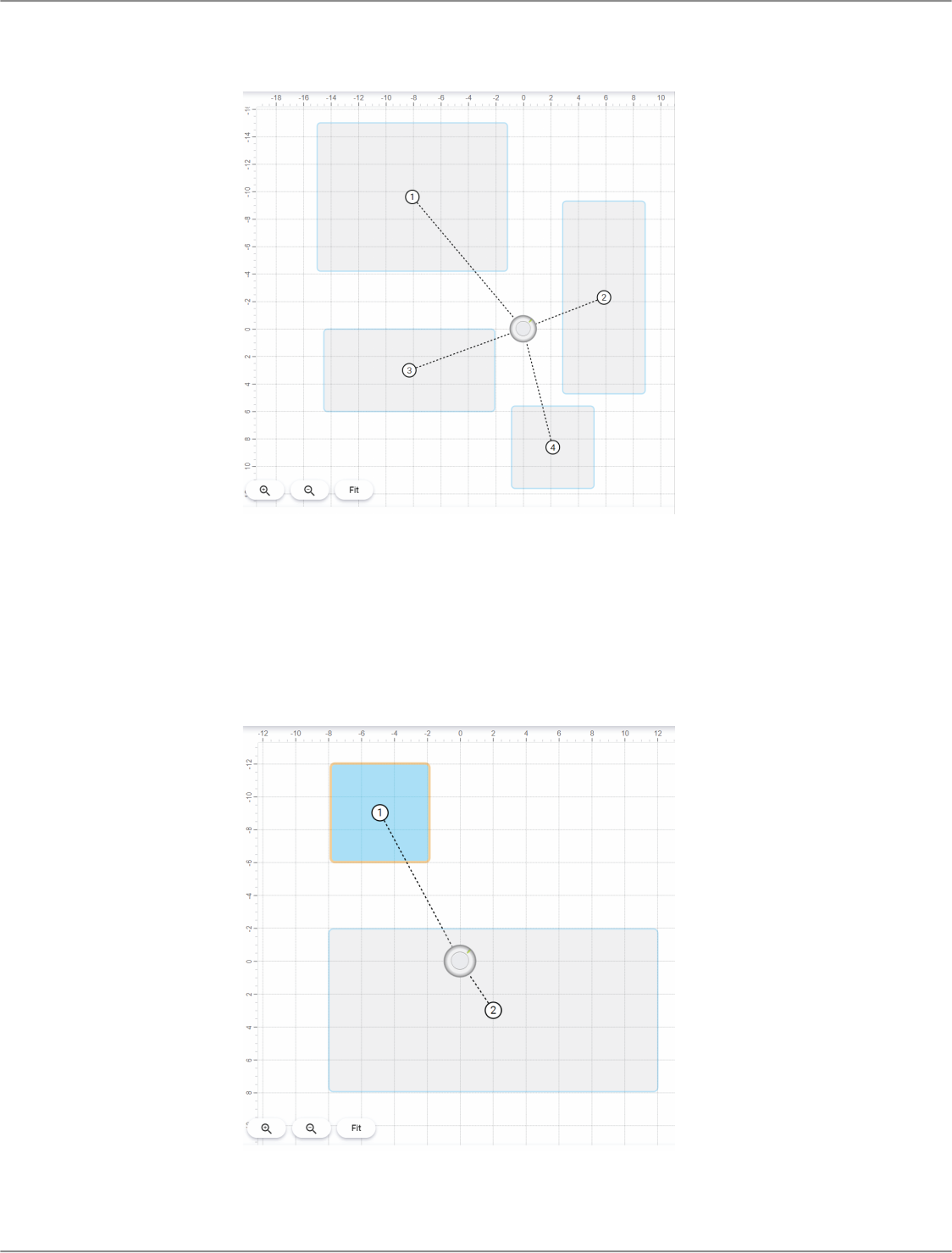
Add Coverage Areas
Automatic coverage = On
When you open Coverage, there's a 30 by 30 foot (9 by 9 meter) dynamic coverage area ready to use. Any talker inside has
coverage, even if they stand up or walk around.
To add coverage areas:
Designer: In the coverage view, select the MXA920, then Properties > Coverage > Add coverage
Web application: Select Add coverage
You can use up to 8 coverage areas per microphone, and you can mix both types as needed. Drag and drop to move coverage
areas.
™
Shure Incorporated
15/54
Dynamic Coverage Areas
Dynamic coverage areas have flexible coverage. The microphone intelligently adapts to cover all talkers in the coverage area.
Change the size to fit your space, and any talker within the boundaries of the coverage area will have microphone coverage
(even as they move).
Dedicated Coverage Areas

Shure Incorporated
16/54
1.
2.
Dedicated coverage areas have microphone coverage at all times. They have a set size of 6 by 6 feet (1.8 by 1.8 meters).
Dedicated coverage works best for talkers that are in one position most of the time, like at a podium or a whiteboard.
Remove Unwanted Sounds with the Virtual Acoustic Boundary
The virtual acoustic boundary adds more power to the edge of the microphone’s coverage area.
When the virtual acoustic boundary is off, the microphone picks up sound that acoustically carries from outside an active cover
age area at low levels. This background sound can still be distracting for listeners.
Turn on the virtual acoustic boundary to remove sound from outside coverage areas. The fader adjusts how much sound from
outside the coverage area is removed from the microphone’s automix output.
Note: The virtual acoustic boundary only works when automatic coverage is on.
To use the virtual acoustic boundary:
In the microphone’s control software, go to IntelliMix > Properties. Scroll down to turn on the virtual acoustic
boundary.
To test, make a call. While you talk, have someone outside of the defined coverage area talk or make noise at the same
time.

Shure Incorporated
17/54
3.
•
•
•
•
1.
2.
1.
◦
◦
2.
•
•
Start with the medium default setting and use the fader to adjust as needed for your room. Have someone on the other
end tell you how your signal sounds.
Tips
A higher setting removes more sound from outside the coverage area. A lower setting removes less sound.
Results may vary in small, highly reverberant rooms. Install acoustic treatment to improve speech intelligibility.
Use Steerable Lobes
Automatic coverage = Off
To use steerable lobes, turn off automatic coverage:
Designer: [Your room] > Coverage > MXA920 > Properties > Coverage > Auto coverage
Web application: Settings > General > Automatic coverage
With automatic coverage off, you can manually position up to 8 microphone lobes. This mode is best for when you need direct
outputs, like for a multi-zone voice lift system. The microphone doesn't use coverage areas when automatic coverage is off.
Refer to the MXA910 guide to learn about using lobes.
Adjust Levels
Before adjusting levels:
Set up a way to listen to the microphone directly using a Dante headphone amp
®
or with Dante Virtual Soundcard.
Open Designer and find the MXA920 in the list of online devices. Alternatively, open the device's web application.
Automatic Coverage On
Talk in each coverage area at a normal speech volume. You can adjust:
Coverage area gain (post-gate): From the room's Coverage view, open the MXA920 properties panel on the right
side. Select the coverage area to see post-gate gain and mute controls.
IntelliMix gain (post-gate): Go to the IntelliMix tab to adjust the automix output level and control DSP settings.
Adjust EQ settings as needed. You can use EQ to improve speech intelligibility and control problematic frequencies in a
room (such as a lowfrequency rumble caused by HVAC systems). If your EQ changes cause a large increase or de
crease in the level, adjust the levels as in step 1.
Automatic Coverage Off
In this mode, there are 2 sets of gain faders:
Channel gain (pre-gate): To adjust, open the MXA920 controls in Designer and go to Channels. These faders affect a
channel's gain before it reaches the automixer and therefore affect the automixer's gating decision. Boosting the gain here
will make the lobe more sensitive to sound sources and more likely to gate on. Lowering gain here makes the lobe less
sensitive and less likely to gate on. If you're only using direct outputs for each channel without the automixer, you only
need to use these faders.
IntelliMix gain (post-gate): To adjust, open the MXA920 controls in Designer and go to IntelliMix. Alternatively, select a
lobe in Coverage to see postgate gain and mute controls in the properties panel. These faders adjust a channel's gain af
ter the lobe has gated on. Adjusting the gain here will not affect the automixer's gating decision. Only use these faders to
adjust the gain of a talker after you are satisfied with the automixer's gating behavior.

Shure Incorporated
18/54
•
•
◦
•
•
◦
•
•
•
•
•
•
•
•
•
•
•
•
•
•
•
•
•
•
•
How to Install the MXA920
There are many ways to install MXA920 microphones. See below for details about the mounting and accessory options for
square and round array microphones.
Microphone Placement Best Practices
Room Variables
Decide where to install the microphone by looking at the room’s seating arrangements and infrastructure. Follow these guide
lines for best results:
Don't install the microphone behind obstructions.
Install the microphone at least 4 feet (1.2 m) from noise sources. These include: air vents, projectors, or loudspeakers that
have high dB levels.
Loudspeakers tend to have higher dB levels when installed above 10 feet (3 m).
In rooms where talkers turn to face a screen, install the microphone toward the screen so talkers naturally talk toward the
microphone.
In rooms with flexible seating arrangements or multiple microphones, use Designer to ensure that the coverage is ade
quate for all seating scenarios.
If installing multiple microphones, set up coverage areas so they don’t overlap.
Install acoustic treatment to improve speech intelligibility in rooms that are too reverberant.
If you’re planning to use X/Y/Z coordinates for camera tracking, install the MXA920 so that it’s level and not angled.
Mounting Height
For most rooms, Shure recommends a mounting height of up to 12 feet (3.7 meters). In rooms with controlled acoustics, you
can install the MXA920 higher than 12 feet and get great results.
Consider the following when choosing a mounting height:
The pickup pattern of the ceiling array is narrower than a shotgun microphone, so it can be placed farther from sound
sources. There is no specific barrier at which the audio degrades or gates off.
Like all microphones, tonality changes as the distance from the source increases.
The pickup area of the microphone increases slightly as it is mounted higher.
Square Mounting Options:
In a ceiling grid
With a VESA mounting device
On NPT pole
Suspend from ceiling with A900-GM
Suspend from ceiling with your own hardware
On 3/8-inch threaded rod
Attach to ceiling with A900-CM
In a hard ceiling
Round Mounting Options:
With a VESA mounting device
On NPT pole
Suspend from ceiling with A900-GM
Suspend from ceiling with your own hardware
On 3/8-inch threaded rod
Attach to ceiling with A900-CM

Shure Incorporated
19/54
•
•
•
•
1.
2.
3.
4.
5.
Installing in a Ceiling Grid
Before you begin:
Remove the plastic cover from the microphone.
If using, install the rubber pads on the corners of the microphone to prevent scratches.
Verify that your ceiling grid size matches your model variation.
If using the A910-JB junction box, install it before ceiling installation.
IMPORTANT: Do not install the 60 cm model in a 2 foot (609.6 mm) ceiling grid.
Make space in the ceiling grid for the array microphone to be installed.
Route the Ethernet cable above the ceiling grid and through the opening in the ceiling.
Plug the Ethernet cable in to the microphone.
Attach the safety tether between the building structure and one of the tie-off points on the back of the microphone using
braided metal cable or other high-strength wire (not included). This safety measure prevents the microphone from
falling in an emergency situation. Make sure there is no tension on the safety tether. Follow any local regulations.
Install the microphone in the ceiling grid.

Shure Incorporated
20/54
Installing the Junction Box Accessory
The A910JB junction box mounts on square ceiling array microphones to connect conduit. There are 3 knockouts on the junc
tion box for attaching conduit. See local regulations to determine if the junction box is necessary.
Note: Install the junction box on the microphone before installing the microphone in the ceiling.

Shure Incorporated
21/54
1.
2.
3.
4.
To install:
Remove the knockout you plan to use on the junction box.
Remove the 4 screws from the microphone as shown.
Align the junction box with the screw holes. If possible, plug the network cable into the microphone before securing the
junction box.
Reinstall the 4 screws to secure the junction box to the microphone.

Shure Incorporated
22/54
•
•
•
•
1.
2.
VESA Standardized Mounting
The rear plate has 4 threaded holes for attaching the microphone to a VESA mounting device. The mounting holes follow the
VESA MIS-D standard:
Screw specification: M4 thread (hole depth = 9.15 mm)
Hole spacing: 100 mm square
The VESA mounting holes work with Shure's A900-PM and A900-PM-3/8IN accessories to mount the microphone on a pole.
Suspending from the Ceiling
Suspend the microphone using your own equipment, or with Shure's A900-GM kit (includes mounting cables and hooks).
To mount using your own equipment, you will need:
Braided metal cable or high-strength wire
Hardware to attach cable to ceiling
Attach the mounting cables to the 12 mm diameter eyelet screws on the microphone.
Attach the cables to the ceiling using the appropriate hardware.
Install on a Ceiling with the A900-CM
Attach array microphones to the ceiling with the A900-CM mounting kit.
Refer to the A900-CM user guide to learn how to install on other ceiling materials.

Shure Incorporated
23/54
•
•
•
•
•
•
•
•
•
•
•
•
Hard Ceiling Mounting
You can mount square ceiling array microphones in hard ceilings without a tile grid using the A910-HCM accessory.
Learn more at www.shure.com.
Dante Channels
The automatic coverage setting changes the number of Dante outputs on the MXA920.
Automatic Coverage On
1 automix output with IntelliMix DSP for all coverage areas
1 AEC reference input
Note: When automatic coverage is on, Dante Controller shows 8 transmit channels and the automix output. The automix output is the only channel that sends
audio with automatic coverage on.
Automatic Coverage Off
Up to 8 separate Dante outputs (1 for each lobe)
1 automix output with IntelliMix DSP
1 AEC reference input
IntelliMix DSP
This device contains IntelliMix digital signal processing blocks that can be applied to the microphone's output. The DSP blocks
include:
Acoustic echo cancellation (AEC)
Automatic gain control (AGC)
Noise reduction
Compressor
Delay
To access, go to the IntelliMix tab.
DSP Best Practices
Apply DSP blocks as needed. Run a test of your system without DSP, and then add processing as needed to fix any is
sues that you hear in the audio signal.
Unless you encounter video that lags behind audio, set delay to off.
Acoustic Echo Cancellation
In audio conferencing, a far-end talker may hear their voice echo as a result of a near-end microphone capturing audio from
loudspeakers. Acoustic echo cancellation (AEC) is a DSP algorithm which identifies the far-end signal and stops it from being
captured by the microphone to deliver clear, uninterrupted speech. During a conference call, the AEC works constantly to opti
mize processing while far-end audio is present.

Shure Incorporated
24/54
•
•
•
•
•
•
•
When possible, optimize the acoustic environment using the following tips:
Reduce loudspeaker volume
Position loudspeakers farther from microphones
Avoid pointing loudspeakers directly at microphone coverage areas
If the microphone is providing AEC on the automix output, turn off AEC on the processor. Designer's auto route applies
these settings automatically.
Select a Reference Signal for AEC
To apply AEC, provide a far end reference signal. For best results, use the signal that also feeds your local reinforcement sys
tem.
P300: Go to Schematic and click any AEC block. Choose the reference source, and the reference source changes for all
AEC blocks.
MXA710, MXA901, MXA910, MXA920: Route a far-end signal to the AEC Reference In channel.
IntelliMix Room: Go to Schematic and click an AEC block. Choose the reference source. Each block can use a different
reference source, so set the reference for each AEC block. When stereo audio is on, you can set different left and right
channel reference sources as needed.
Designer's auto route process automatically routes an AEC reference source. However, you should check that Designer choos
es the reference source you want to use.
Note: Always send an AEC reference signal to microphones with AEC processing, even if you are using a separate DSP for AEC. Designer's auto route fea
ture automatically creates these routes.
AEC Settings
Reference Meter
Use the reference meter to visually verify the reference signal is present. The reference sig
nal should not be clipping.
ERLE
Echo return loss enhancement (ERLE) displays the dB level of signal reduction (the amount
of echo being removed). If the reference source is connected properly, the ERLE meter ac
tivity generally corresponds to the reference meter.
Reference Indicates which channel is serving as the far end reference signal.
Non-Linear Processing
The primary component of the acoustic echo canceller is an adaptive filter. Nonlinear pro
cessing supplements the adaptive filter to remove any residual echo caused by acoustic ir
regularities or changes in the environment. Use the lowest possible setting that is effective in
your room.
Low: Use in rooms with controlled acoustics and minimal echoes. This setting provides the
most natural sound for full duplex.
Medium: Use in typical rooms as a starting point. If you hear echo artifacts, try using the
high setting.
High: Use to provide the strongest echo reduction in rooms with bad acoustics, or in situa
tions where the echo path frequently changes.
Auto (default)*: For best results, use this setting. The nonlinear processing level automati
cally adapts to changes in the acoustic environment.
* Auto setting available in firmware 6.2 and newer for MXA920, MXA902, MXA901, and MXA710

Shure Incorporated
25/54
Noise Reduction
Noise reduction significantly reduces the amount of background noise in your signal caused by projectors, HVAC systems, or
other environmental sources. It is a dynamic processor, which calculates the noise floor in the room and removes noise
throughout the entire spectrum with maximum transparency.
Settings
Options: Low, medium, high, or auto*
The noise reduction setting reflects the amount of reduction in dB. For best results, use the auto setting so that the noise re
duction level adapts to changes in the acoustic environment.
* Auto setting available in firmware 6.2 and newer for MXA920, MXA902, MXA901, and MXA710
Automatic Gain Control (AGC)
Automatic gain control automatically adjusts channel levels to ensure consistent volume for all talkers in all scenarios. For qui
eter voices, it increases gain. For louder voices, it attenuates the signal.
Enable AGC on channels where the distance between the talker and the microphone may vary, or in rooms where many differ
ent people will use the conferencing system.
Automatic gain control happens post-gate (after the automixer) and does not affect when the automixer gates on or off.
Target Level (dBFS)
Use −37 dBFS as a starting point to ensure adequate headroom and adjust if necessary. This represents the RMS (aver
age) level, which is different from setting the input fader according to peak levels to avoid clipping.
Maximum Boost ( dB)
Sets the maximum amount of gain that can be applied
Maximum Cut ( dB)
Sets the maximum attenuation that can be applied
Tip: Use the boost/cut meter (not available on all microphones) to monitor the amount of gain added or subtracted from the
signal. If the meter is always reaching the maximum boost or cut level, adjust the input fader so the signal is closer to the target
level.
Delay
Use delay to synchronize audio and video. When a video system introduces latency (where you hear someone speak, and
their mouth moves later), add delay to align audio and video.
Delay is measured in milliseconds. If there is a significant difference between audio and video, start by using larger intervals of
delay time (500-1000 ms). When the audio and video are slightly out of sync, use smaller intervals to fine-tune.
Compressor
Use the compressor to control the dynamic range of the selected signal.
Threshold
When the audio signal exceeds the threshold value, the level is attenuated to prevent unwanted spikes in the output sig
nal. The amount of attenuation is determined by the ratio value. Perform a soundcheck and set the threshold 3-6 dB above
average talker levels, so the compressor only attenuates unexpected loud sounds.
Ratio

Shure Incorporated
26/54
•
•
•
•
The ratio controls how much the signal is attenuated when it exceeds the threshold value. Higher ratios provide stronger
attenuation. A lower ratio of 2:1 means that for every 2 dB the signal exceeds the threshold, the output signal will only ex
ceed the threshold by 1 dB. A higher ratio of 10:1 means a loud sound that exceeds the threshold by 10 dB will only ex
ceed the threshold by 1 dB, effectively reducing the signal by 9 dB.
Parametric Equalizer
Maximize audio quality by adjusting the frequency response with the parametric equalizer.
Common equalizer applications:
Improve speech intelligibility
Reduce noise from HVAC systems or video projectors
Reduce room irregularities
Adjust frequency response for reinforcement systems
Setting Filter Parameters
Adjust filter settings by manipulating the icons in the frequency response graph, or by entering numeric values. Disable a filter
using the checkbox next to the filter.
PEQ Filter Settings
Setting Function
Filter Type
Only the first and last band have selectable filter types.
Parametric: Attenuates or boosts the signal within a cus
tomizable frequency range
Low Cut: Rolls off the audio signal below the selected fre
quency
Low Shelf: Attenuates or boosts the audio signal below the
selected frequency
High Cut: Rolls off the audio signal above the selected fre
quency
High Shelf: Attenuates or boosts the audio signal above the
selected frequency
Frequency Select the center frequency of the filter to cut or boost
Gain Adjusts the level for a specific filter (+/− 18 dB)
Q
Adjusts the range of frequencies affected by the filter. As this
value increases, the bandwidth becomes thinner.
Width
Adjusts the range of frequencies affected by the filter. The
value is represented in octaves.
Note: The Q and width parameters affect the equalization curve in the same
way. The only difference is the way the values are represented.

Shure Incorporated
27/54
1.
2.
3.
Copy and Paste Equalizer Channel Settings
Use to quickly apply the same PEQ setting across multiple channels.
Select the PEQ of the desired channel.
Click copy.
Select the channel to apply the PEQ setting to and click paste.
Equalizer Applications
Conferencing room acoustics vary based on room size, shape, and construction materials. Use the guidelines in following ta
ble.
Uses for EQ
EQ Application Suggested Settings
Treble boost for improved speech intelligibility
Add a high shelf filter to boost frequencies greater than 1
kHz by 3-6 dB
HVAC noise reduction Add a low cut filter to attenuate frequencies below 200 Hz

Shure Incorporated
28/54
1.
2.
3.
1.
2.
3.
•
•
1.
2.
•
EQ Application Suggested Settings
Reduce flutter echoes and sibilance
Identify the specific frequency range that "excites" the room:
Set a narrow Q value.
Increase the gain to between +10 and +15 dB, and
then experiment with frequencies between 1 kHz and
6 kHz to pinpoint the range of flutter echoes or sibi
lance.
Reduce the gain at the identified frequency (start be
tween −3 and −6 dB) to minimize the unwanted room
sound.
Reduce hollow, resonant room sound
Identify the specific frequency range that "excites" the room:
Set a narrow Q value.
Increase the gain to between +10 and +15 dB, and
then experiment with frequencies between 300 Hz
and 900 Hz to pinpoint the resonant frequency.
Reduce the gain at the identified frequency (start be
tween −3 and −6 dB) to minimize the unwanted room
sound.
EQ Contour
Use the EQ contour to quickly apply a high-pass filter at 150 Hz to the microphone's signal.
Select EQ contour to turn it on or off.
Automix
Automix Channel
This channel automatically mixes the audio from all selected channels to a single output. To adjust the automix channel set
tings, go to:
MXA710, MXA910, MXA920:[Your device] > IntelliMix > Properties
P300 and IntelliMix Room:[Your device] > Automixer > Properties
All IntelliMix DSP blocks can be applied to the automix channel.
To use the automix channel, do the following:
Check that Send to mix is automatically selected (blue) for all channels. To exclude channels from the automix channel
and treat them as individual direct outputs, deselect Send to mix (gray).
Route the automix channel in Designer or Dante Controller.
Automix Settings
Use these settings to adjust the automixer. Designer adjusts these settings automatically if you use the auto route feature, but
you can customize to fit your installation. To adjust, go to:
MXA710, MXA910, MXA920:[Your device] > IntelliMix > Properties

Shure Incorporated
29/54
• P300 and IntelliMix Room:[Your device] > Automixer > Properties
Automix Settings
Setting Function
Leave last mic on
Keeps the most recently used microphone channel active.
The purpose of this feature is to keep natural room sound in
the signal so that meeting participants on the far end know
the audio signal has not been interrupted.
Gating sensitivity
Changes the threshold of the level at which the gate is
opened
Off attenuation
Sets the level of signal reduction when a channel is not ac
tive
Hold time
Sets the duration for which the channel remains open after
the level drops below the gate threshold
Maximum open channels
Sets the maximum number of simultaneously active chan
nels
Automix gain meter
When enabled, changes gain meters to display automix gat
ing in real time. Channels that gate open will display more
gain than channels that are closed (attenuated) in the mix.
Priority
When selected, this channel gate activates regardless of the
number of maximum open channels.
Always on When selected, this channel will always be active.

Shure Incorporated
30/54
•
◦
◦
◦
•
◦
◦
•
•
•
Setting Function
Send to mix When selected, sends the channel to the automix channel.
Solo Mutes all of the other channels
Note: Not all settings are available on all automixers.
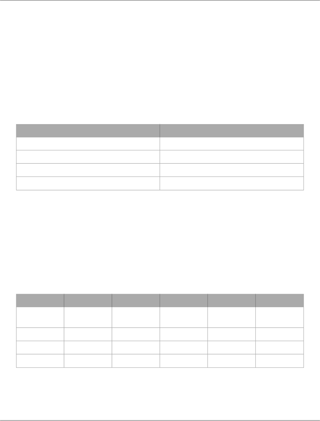
Speech Gating Threshold and Enhanced Noise Filtering
Speech gating threshold and enhanced noise filtering work together to enhance the microphone's sound.
Speech gating threshold:
Provides increased control over the automixer gating decision, focusing on speech sources over noise sources
Low setting preserves speech better
High setting is more aggressive at gating off for noise sources
Enhanced noise filtering:
Removes noise from the automix output signal
Is designed for noises that are inside a microphone’s coverage area but that are not located next to a person talking
Examples of noise include:
Shuffling papers across the table from a person talking
Keyboard across the table from a person talking
Loud food container across the table from a person talking
Shure DSP Features for Noise
DSP Feature Purpose Available in:
Noise reduction
Removes constant background noise
(such as HVAC)
All devices with IntelliMix DSP
Enhanced noise filtering
Removes noise sources that:
Are in the microphone's coverage area
Are not immediately next to a person
talking. Example: If a person talking
opens a bag of chips, you will still hear
the bag.
Firmware 6.2 and newer for:
MXA710, MXA901, MXA902: On or off
settings
MXA920: Low, medium, or high settings
AI denoiser
Removes any noise, even noise that
happens immediately next to a person
talking
IntelliMix Room software
In this example, enhanced noise filtering removes loud typing sounds happening on one end of coverage area 2 and focuses
on the person speaking.

Shure Incorporated
31/54
1.
2.
3.
4.
•
•
•
•
•
Speech gating threshold and enhanced noise filtering work when automatic coverage is on or off.
To use speech gating threshold and enhanced noise filtering:
In the microphone’s control software, go to IntelliMix > Properties. Scroll down to adjust the 2 settings.
Make a test call in a room with 2 people to test the speech gating threshold and enhanced noise filtering settings. Start
with both settings at the highest level.
Have both people in the room talk at the same time. The far-end listener should listen for unwanted speech attenuation.
If there is speech attenuation, lower the speech gating threshold. Repeat until there is no unwanted speech attenuation.
Next, have one person talk and the other person create noise at the same time (use the examples for ideas). The noise
source should be away from the person talking. The farend listener should tell you how the signal sounds. Test and ad
just the enhanced noise filtering level as needed.
Tips:
A high speech gating threshold may detect unvoiced speech sound as noise. If you notice this, lower the speech gating
threshold.
If the microphone is routed to IntelliMix Room and you’re using the AI denoiser feature, turn off enhanced noise filtering.
If using with automatic coverage off and leave last mic on set to off, set the speech gating threshold to low. With this setup,
the microphone won’t gate off if speech is quiet in comparison to noise.
Automix Modes
To select an automix mode, go to:
MXA710, MXA910, MXA920:[Your device] > IntelliMix > Properties
P300 and IntelliMix Room:[Your device] > Automixer > Properties

Shure Incorporated
32/54
•
•
•
•
◦
1.
◦
1.
Gating
Gating mode delivers fast-acting, seamless channel gating and consistent perceived ambient sound levels. The off attenuation
setting is applied to all inactive channels, regardless of the number of active channels.
Gain Sharing
Gain sharing mode dynamically balances system gain between open and closed channels. The system gain remains consis
tent by distributing gain across channels to equal one open channel. The scaled gain structure helps to reduce noise when
there is a high channel count. When fewer channels are used, the off attenuation setting is lower and provides transparent gat
ing.
Manual
Manual mode sums all active tracks and sends the summed signal over a single Dante output. This provides the option to route
an individual signal for reinforcement or recording, without enabling automixing. The settings from the faders in the standard
monitoring view apply to the summed output.
Encryption
Audio is encrypted with the Advanced Encryption Standard (AES-256), as specified by the US Government National Institute of
Standards and Technology (NIST) publication FIPS-197. Shure devices that support encryption require a password to make a
connection. Encryption is not supported with third-party devices.
In Designer, you can turn on encryption for all devices in a room: [Your room] > Settings > Audio encryption.
To activate encryption in the web application, go to Settings > Audio encryption > Enable encryption.
Important: For encryption to work:
All Shure devices on your network must use encryption.
Disable AES67 in Dante Controller. AES67 and AES-256 cannot be used at the same time.
Set Up the 802.1X Protocol for a Device
Select Shure devices support the IEEE 802.1X port access protocol for network authentication.
Important: To use the 802.1X security protocol with Shure devices, set the network switch to multiple host authentication. You
must also make accommodations to allow the audio NIC to connect to the network. The audio NIC doesn't support the 802.1X
protocol.
Setting up 802.1X is a two-part process.
To set up 802.1X, you will need:
Details about your authentication server's EAP method
Any required credentials or certificates for that method, for example:
MD5 and PWD
User ID and passphrase
TLS and PEAP
User ID and passphrase

Shure Incorporated
33/54
2.
•
1.
2.
3.
4.
5.
6.
7.
1.
2.
3.
4.
•
•
1.
2.
3.
4.
Certificate (with certificate types) in the .PEM format
Any passwords to access the devices if they are password locked
Step 1: Configure Settings on Test Network
Connect the device to your test network and discover it using Designer.
Set a device password if desired.
Double-click the device and go to Settings > Network > 802.1X.
Choose your EAP method from the menu.
Enter any required credentials and load any necessary certificates.
Press Save to save the 802.1X settings to the device.
Enable 802.1X and select Reboot later.
Step 2: Connect to a Credentialed Network
Connect your device to the credentialed network.
Ensure that Designer is connected to the credentialed network.
Go to Settings > Network > 802.1X and enable 802.1X. Reboot the device for the 802.1X settings to take effect.
If the device doesn’t appear in Designer after the reboot, reconnect to the test network and check all 802.1X settings for
the selected EAP method.
Turn Off or Clear 802.1X Settings
You can turn off 802.1X settings temporarily, or clear them from the device. Open the device and go to Settings > Network
> 802.1X
Disable: Click the 802.1X switch to turn off 802.1X settings. Click the switch again to enable 802.1X.
Clear: Click Clear 802.1X settings to remove 802.1X settings from the device.
Note: Resetting to factory default clears all 802.1X settings.
Change 802.1X Settings
You may need to change a device’s 802.1X settings if the enterprise’s 802.1X settings are changing. The best way to do this is
to change the 802.1X settings on the devices, and then make changes to the authentication server.
To change device settings:
While still connected to the credentialed network, find the device in Designer and go to Settings > Network >
802.1X.
Make changes and click Save.
Make any changes to the authentication server.
Reboot your devices. The devices should connect to the credentialed network with the updated 802.1X settings.
Troubleshooting 802.1X Setup Issues
If the device doesn’t appear in Designer on the credentialed network, there’s a problem with the device’s 802.1X settings. To
troubleshoot, take the device off the credentialed network and connect it to the test network. You can make any necessary
changes to the 802.1X settings, and then reconnect to the credentialed network.
If you attempt to enable 802.1X on a device, but the authentication fails, you will see this notification:

Shure Incorporated
34/54
•
•
•
•
•
•
•
•
•
•
•
•
•
•
•
◦
•
◦
◦
If this occurs, check with your system administrator.
Networking Best Practices
When connecting Shure devices to a network, use the following best practices:
Always use a "star" network topology by connecting each device directly to the switch or router.
Connect all Shure networked devices to the same network and set to the same subnet.
Allow all Shure software through the firewall on your computer.
Use only 1 DHCP server per network. Disable DHCP addressing on additional servers.
Power on the switch and DHCP server before powering on the Shure devices.
To expand the network, use multiple switches in a star topology.
All devices must be at the same firmware revision level.
Switch and Cable Recommendations for Dante Networking
Switches and cables determine how well your audio network performs. Use highquality switches and cables to make your au
dio network more reliable.
Network switches should have:
Gigabit ports. 10/100 switches may work on small networks, but gigabit switches perform better.
Power over Ethernet (PoE) or PoE+ ports for any devices that require power
Management features to provide information about port speed, error counters, and bandwidth used
Ability to switch off Energy Efficient Ethernet (EEE). EEE (also known as "Green Ethernet") may cause audio dropouts and
problems with clock synchronization.
Diffserv (DSCP) Quality of Service (QoS) with strict priority and 4 queues
Ethernet cables should be:
Cat5e or better
Shielded
For more information, see our FAQ about switches to avoid.
Device IP Configuration
This Shure device uses 2 IP addresses: one for Shure control, and one for Dante audio and control. For most installations, the
Shure control and Dante audio IP addresses should be in the same subnet range.
Shure control
Carries data for Shure control software, firmware updates, and third-party control systems (such as AMX or Crestron)
Dante audio and control
Carries Dante digital audio and control data for Dante Controller
Requires a wired, gigabit Ethernet connection to operate
Shure Incorporated
35/54
•
•
To access these settings in Designer, go to [Your device] > Settings > IP configuration.
Note:Refer to our FAQ if you're using Shure profiles on NETGEAR M4250-series switches.
Setting Latency
Latency is the amount of time for a signal to travel across the system to the outputs of a device. To account for variances in la
tency time between devices and channels, Dante has a predetermined selection of latency settings. When the same setting is
selected, it ensures that all Dante devices on the network are in sync.
These latency values should be used as a starting point. To determine the exact latency to use for your setup, deploy the set
up, send Dante audio between your devices, and measure the actual latency in your system using Audinate's Dante Controller
software. Then round up to the nearest latency setting available, and use that one.
Use Audinate's Dante Controller software to change latency settings.
Latency Recommendations
Latency Setting Maximum Number of Switches
0.25 ms 3
0.5 ms (default) 5
1 ms 10
2 ms 10+
QoS (Quality of Service) Settings
QoS settings assign priorities to specific data packets on the network, ensuring reliable audio delivery on larger networks with
heavy traffic. This feature is available on most managed network switches. Although not required, assigning QoS settings is
recommended.
Note: Coordinate changes with the network administrator to avoid disrupting service.
To assign QoS values, open the switch interface and use the following table to assign Dante -associated queue values.
Assign the highest possible value (shown as 4 in this example) for time-critical PTP events
Use descending priority values for each remaining packet.
Dante QoS Priority Values
Priority Usage DSCP Label Hex Decimal Binary
High (4)
Time-critical PTP
events
CS7 0x38 56 111000
Medium (3) Audio, PTP EF 0x2E 46 101110
Low (2) (reserved) CS1 0x08 8 001000
None (1) Other traffic BestEffort 0x00 0 000000
Note: Switch management may vary by manufacturer and switch type. Consult the manufacturer's product guide for specific configuration details.
For more information on Dante requirements and networking, visit www.audinate.com.
®

Shure Incorporated
36/54
Networking Terminology
PTP (Precision Time Protocol): Used to synchronize clocks on the network
DSCP (Differentiated Services Code Point): Standardized identification method for data used in layer 3 QoS prioritization
IP Ports and Protocols
This list may change with new firmware releases. Current IP ports and protocols:
Shure Control
Port TCP/UDP Protocol Description
Factory De
fault
21 TCP FTP Required for firmware updates (otherwise closed) Closed
22 TCP SSH Secure Shell Interface Closed
23 TCP Telnet Not supported Closed
53 UDP DNS Domain Name System Closed
67 UDP DHCP Dynamic Host Configuration Protocol Open
68 UDP DHCP Dynamic Host Configuration Protocol Open
80* TCP HTTP Required to launch embedded web server Open
443** TCP HTTPS HTTPS/device API/camera tracking Closed
2202 TCP ASCII Required for 3rd party control strings Open
5353 UDP mDNS Required for device discovery Open
57383 UDP SDT (unicast) Required for inter-device communication Open
8023 TCP Telnet Debug console interface Closed
8180 TCP HTML Required for web application (legacy firmware only) Open
8427 UDP SLP Required for inter-device communication Open
64000 TCP Telnet Required for Shure firmware update Open
*These ports must be open on the PC or control system to access the device through a firewall.
**Some firmware supports HTTPS. HTTPS isn't available for all devices.
These protocols require multicast. Ensure multicast has been correctly configured for your network.
Refer to Audinate's website for information about ports and protocols used by Dante audio.
†
†
†

Shure Incorporated
37/54
•
•
•
Digital Audio Networking
Dante digital audio is carried over standard Ethernet and operates using standard internet protocols. Dante provides low laten
cy, tight clock synchronization, and high QualityofService (QoS) to provide reliable audio transport to a variety of Dante de
vices. Dante audio can coexist safely on the same network as IT and control data, or can be configured to use a dedicated net
work.
Compatibility with Dante Domain Manager
This device is compatible with Dante Domain Manager software (DDM). DDM is network management software with user au
thentication, role-based security, and auditing features for Dante networks and Dante-enabled products.
Considerations for Shure devices controlled by DDM:
When you add Shure devices to a Dante domain, set the local controller access to Read Write. Otherwise, you won't be
able to access Dante settings, perform a factory reset, or update device firmware.
If the device and DDM can't communicate over the network for any reason, you won't be able to control Dante settings,
perform a factory reset, or update device firmware. When the connection is reestablished, the device follows the policy set
for it in the Dante domain.
If Dante device lock is on, DDM is offline, or the configuration of the device is set to Prevent, some device settings are dis
abled. These include: Dante encryption, MXW association, AD4 Dante browse and Dante cue, and SCM820 linking.
Refer to Dante Domain Manager's documentation for more information.
Dante Flows for Shure Devices
Dante flows get created any time you route audio from one Dante device to another. One Dante flow can contain up to 4 audio
channels. For example: sending all 5 available channels from an MXA310 to another device uses 2 Dante flows, because 1
flow can contain up to 4 channels.
Every Dante device has a specific number of transmit flows and receive flows. The number of flows is determined by Dante
platform capabilities.
Dante Flows for Shure Devices
Dante Platform
Shure Devices Using Plat
form
Transmit Flow Limit Receive Flow Limit
Brooklyn II
ULX-D, SCM820, MXWAPT,
MXWANI, P300, MXCWAPT
32 32
Brooklyn II (without SRAM)
MXA920, MXA910, MXA902,
MXA710, AD4, AD600,
APXD2
16 16
IP Core
MXA920-V3, MXA902-V3,
MXA901
32 32
Ultimo/UltimoX
MXA310, ANI4IN, ANI4OUT,
ANIUSB-MATRIX, ANI22,
MXN5-C
2 2
DEP ANIUSB-MATRIX-V3 2 2
DAL IntelliMix Room 16 16
Learn more about Dante flows in our FAQs or from Audinate.

Shure Incorporated
38/54
•
•
•
1.
2.
3.
4.
1.
AES67
AES67 is a networked audio standard that enables communication between hardware components which use different IP au
dio technologies. This Shure device supports AES67 for increased compatibility within networked systems for live sound, inte
grated installations, and broadcast applications.
The following information is critical when transmitting or receiving AES67 signals:
Update Dante Controller software to the newest available version to ensure the AES67 configuration tab appears.
Before turning encryption on or off, you must disable AES67 in Dante Controller.
AES67 cannot operate when the transmit and receive devices both support Dante.
Shure Device Supports: Device 2 Supports: AES67 Compatibility
Dante and AES67 Dante and AES67 No. Must use Dante.
Dante and AES67
AES67 without Dante. Any other au
dio networking protocol is acceptable.
Yes
Separate Dante and AES67 flows can operate simultaneously. The total number of flows is determined by the maximum flow
limit of the device.
Sending Audio from a Shure Device
All AES67 configuration is managed in Dante Controller software. For more information, refer to the Dante Controller user
guide.
Open the Shure transmitting device in Dante Controller.
Enable AES67.
Reboot the Shure device.
Create AES67 flows according to the instructions in the Dante Controller user guide.
Receiving Audio from a Device Using a Different Audio Network Protocol
Third-party devices: When the hardware supports SAP, flows are identified in the routing software that the device uses. Oth
erwise, to receive an AES67 flow, the AES67 session ID and IP address are required.
Shure devices: The transmitting device must support SAP. In Dante Controller, a transmit device (appears as an IP address)
can be routed like any other Dante device.
Paint the MXA920
Paint Square Array Microphones
You can paint the grille and frame of square ceiling array microphones to blend in with a room's design.
Note: Don't remove any of the screws on the MXA902's loudspeaker enclosure while painting.
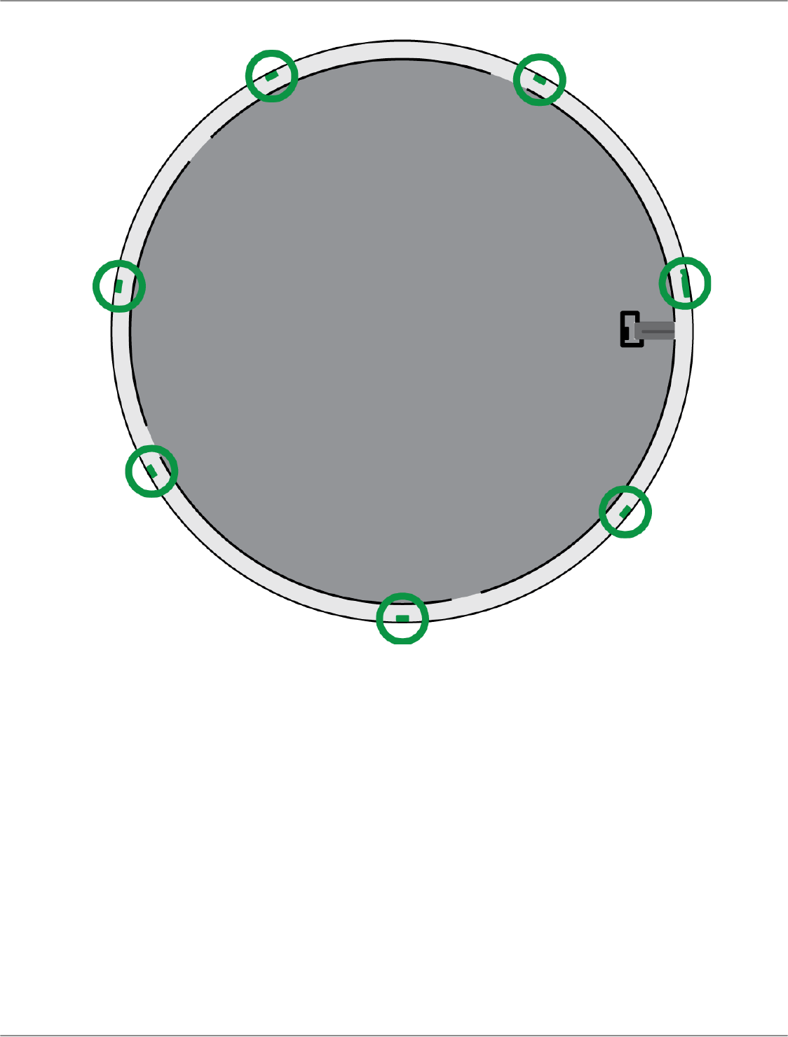
Step 1: Remove the Frame and Grille
On each side of the frame, remove the 6 screws and washers that attach the main assembly to the frame.
Important: Do not remove the 4 recessed screws in each corner.

Shure Incorporated
39/54
2.
3.
4.
5.
6.
7.
1.
Carefully lift the assembly out of the frame.
Remove the gray plastic LED lightpipe. Leave the black plastic guide in place.
Remove all 4 recessed screws from one side of the frame. Remove that side of the frame.
Slide the flat grille out of the frame.
Carefully remove the foam piece from the grille. Pull from the edges, where it is attached with hook-and-loop fastener
strips.
Important: Do not paint the foam.
Before painting, reinstall the side of the frame you removed in step 1.4.
Step 2: Mask and Paint
Use masking tape to cover the entire extrusion (highlighted in black) that runs along the inside of the frame. This en
sures that the necessary metal pieces make contact when reassembled.

Shure Incorporated
40/54
2.
3.
1.
2.
3.
4.
5.
6.
1.
Use masking tape to cover the hook-and-loop fastener strips on the grille.
Paint the frame and grille. Let them dry completely before reassembling. Do not paint any part of the main assembly.
Step 3: Reassembly
Attach the foam piece to the grille with the hook-and-loop fastener strips.
Remove one side of the frame as in step 1.4. Slide the grille back into the frame.
Attach the remaining side of the frame and secure it with the 4 screws.
Attach the LED lightpipe to the black plastic guide piece.
Align the LED with the lightpipe and put the main assembly back in place on the frame.
Note: The label on the assembly is in the corner that corresponds to the LED.
Install 6 screws per side to secure the main assembly to the frame. Do not over-tighten.
Paint MXA920-R Microphones
The grille and back cover of round array microphones can be painted to blend in with a room's design.
Step 1: Remove and Paint the Grille
Loosen the set screw that connects the grille to the back cover. Turn the microphone over.

Shure Incorporated
41/54
2. Rotate the grille as shown to release it from the back cover. Lift it up and out of the tabs holding it in place.

Shure Incorporated
42/54
3.
4.
5.
Carefully remove the fabric piece from the grille. Pull from the edges where it is attached with Velcro strips. Do not paint
the fabric.
Hold the edges of the black plastic guide in place and pull up on the clear lightpipe to unsnap it. Leave the guide in
place.
Mask the 7 bare metal tabs on the grille.
Shure Incorporated
43/54
6.
1.
Paint the grille.
Step 2: Remove and Paint the Back Cover
Remove the 7 screws on the aluminum support panel. Turn the back cover over.

Shure Incorporated
44/54
2. Remove the 12 screws that attach the back cover to the processor enclosure. Set the processor enclosure aside with
the black board facing up.

Shure Incorporated
45/54
3.
4.
1.
2.
3.
4.
5.
Mask the entire flat area in the center of the back cover. Mask the 7 tabs on the inside of the back cover to keep paint
out of the screw threads.
Paint the outside of the back cover.
Step 3: Reassemble the Microphone
Let the paint dry before reassembling.
Use the 12 screws to attach the back cover to the processor.
Use the 7 screws to reattach the aluminum support panel.
Reinstall the lightpipe on the grille by snapping it into place.
Attach the fabric piece to the grille.
Align the grille with the 7 tabs on the back cover. Set it down and rotate the grille as shown to engage the tabs.

Shure Incorporated
46/54
6.
•
•
•
Tighten the set screw.
Monitor and Control with External Systems
Use the REST API
This device has a REST API for easy integration with other enterprise monitoring and control solutions. Use the API to control
this device with third-party monitoring and control systems.
Common applications:
Mute
LED color and behavior
Receive coverage information
Shure continues to add API capabilities. Find our complete API documentation at shure.stoplight.io.

Shure Incorporated
47/54
•
•
•
•
•
•
The device's API is on by default. To restrict access to the API, go to Settings > Services in Designer or the device's web
application.
Available in firmware 6.2 and newer
Use Command Strings
This device receives logic commands over the network. Many parameters controlled through Designer can be controlled using
a third-party control system, using the appropriate command string.
Common applications:
Mute
LED color and behavior
Loading presets
Adjusting levels
A complete list of command strings is available at:
shure.com/docs/commandstrings/mxa920
Integrate the MXA920 with Camera Control Systems
MXA920 microphones provide data about talker position, lobe position, and other settings. You can use this data to integrate
the microphone with camera control systems.
There are 2 ways to access the data:
Option 1: Use the REST API
Option 2: Use command strings
Troubleshooting
MXA920 Troubleshooting
Problem Solution
Audio is not present or is quiet/distorted
Check cables.
Verify that output channel isn't muted.
Check that output levels are not set too low.
Sound quality is muffled or hollow
Check that coverage area is positioned correctly.
Use EQ to adjust frequency response.
Microphone does not power on
Check that microphone is plugged in to a PoE source.
Check network cables and connections.
Microphone doesn't show up in Designer
Ensure that microphone has power.
Make sure microphone is on the same network and subnet
as PC.

Shure Incorporated
48/54
•
•
•
•
•
•
•
•
•
•
Problem Solution
Turn off network interfaces not used to connect to the device
(such as Wi-Fi).
Check that DHCP server is functioning (if applicable).
Reset the device if necessary.
Refer to no online devices FAQ for more help.
Microphone doesn't show up in Shure Web Device Dis
covery
Ensure that microphone has power.
Check that Shure Web Device Discovery is updated.
Make sure microphone is on the same network as PC.
Check that DHCP server is functioning (if applicable).
Reset the device if necessary.
Refer to the devices don't appear FAQ for more help.
Flashing red error LED
In the web application, go to Settings > General > Ex
port log to export the device event log. Use the event log
to get more information and contact Shure if necessary.
No lights
Go to [Your device] > Settings > Lights. Check if
brightness is disabled or if any other settings are turned off.
If the device is in a room using Designer's call status feature,
mute status LEDs are off when not in a call.
Web application lags in Google Chrome browser Turn off hardware acceleration option in Chrome.
Additional Resources
Shure Knowledge Base FAQs
Command strings for Shure devices
Shure API documentation
Shure Enterprise Networking Troubleshooting Checklist
Training from the Shure Audio Institute
Shure Systems YouTube channel
Download Shure Software
Shure Designer
Shure Update Utility
Shure Web Device Discovery
Software and firmware archive

Shure Incorporated
49/54
Specifications
General
Coverage Type
Automatic or steerable
Power Requirements
Power over Ethernet (PoE), Class 0
Power Consumption
10.1 W maximum
Control Software
Designer or web application
Cable Requirements
Cat5e or higher (shielded cable recommended)
Connector Type
RJ45
Plenum Rating
MXA920-S UL2043 (Suitable for Air Handling Spaces)
MXA920-R Not rated
Dust Protection
IEC 60529 IP5X Dust Protected
Operating Temperature Range
−6.7°C (20°F) to 40°C (104°F)
Storage Temperature Range
−29°C (−20°F) to 74°C (165°F)
Audio
Microphone Elements
113 MEMS
Frequency Response
125 Hz to 20,000 Hz
AES67 or Dante Digital Output
Channel
Count
Automatic coverage
on
2 total channels (1 output, 1 AEC reference in channel)

Shure Incorporated
50/54
Automatic cover
age off
10 total channels (8 independent transmit channels, 1 automix output, 1
AEC reference in channel)
Sampling Rate 48 kHz
Bit Depth 24
Sensitivity
at 1 kHz
−1.74 dBFS/Pa
Maximum SPL
Relative to 0 dBFS overload
95.74 dBSPL
Signal-to-Noise Ratio
Ref. 94 dBSPL at 1 kHz
75.76 dB Aweighted
Latency
Does not include Dante latency
Direct outputs (Automatic coverage off) 15.9 ms
Automix output (Includes IntelliMix processing) 26.6 ms
Self Noise
18.24 dB SPLA
Dynamic Range
77.5 dB
Digital Signal Processing
Automatic mixing, acoustic echo cancellation (AEC), noise reduction, automatic gain control, compressor,
delay, equalizer (4band parametric), mute, gain (140 dB range)
Acoustic Echo Cancellation Tail Length
Up to 250 ms
MXA920 Frequency Response
Frequency response measured directly on-axis from a distance of 6 feet (1.83 m).

Shure Incorporated
51/54
•
•
•
•
•
•
•
•
•
1.
2.
3.
Dimensions
Weight
MXA920-S: 11.8 lbs (5.4 kg)
MXA920-R: 12.7 lbs (5.8 kg)
MXA920-S
A (Microphone flange): 0.41 in. (10.5 mm)
B (Edge to edge): 23.77 in. (603.8 mm)
C (Height): 2.15 in. (54.69 mm)
MXA920-S-60CM
A (Edge to edge): 23.38 in. (593.8 mm)
B (Height): 2.15 in. (54.69 mm)
MXA920-R
A (Height to top of eyelets): 2.4 in. (61.3 mm)
B (Outer diameter): 25 in. (635.4 mm)
IMPORTANT SAFETY INSTRUCTIONS
READ these instructions.
KEEP these instructions.
HEED all warnings.

Shure Incorporated
52/54
4.
5.
6.
7.
8.
9.
10.
11.
12.
13.
14.
15.
16.
17.
18.
19.
20.
21.
FOLLOW all instructions.
DO NOT use this apparatus near water.
CLEAN ONLY with dry cloth.
DO NOT block any ventilation openings. Allow sufficient distances for adequate ventilation and install in accordance
with the manufacturer’s instructions.
DO NOT install near any heat sources such as open flames, radiators, heat registers, stoves, or other apparatus (in
cluding amplifiers) that produce heat. Do not place any open flame sources on the product.
DO NOT defeat the safety purpose of the polarized or grounding type plug. A polarized plug has two blades with one
wider than the other. A grounding type plug has two blades and a third grounding prong. The wider blade or the third
prong are provided for your safety. If the provided plug does not fit into your outlet, consult an electrician for replace
ment of the obsolete outlet.
PROTECT the power cord from being walked on or pinched, particularly at plugs, convenience receptacles, and the
point where they exit from the apparatus.
ONLY USE attachments/accessories specified by the manufacturer.
USE only with a cart, stand, tripod, bracket, or table specified by the manufacturer, or sold with the apparatus. When a
cart is used, use caution when moving the cart/apparatus combination to avoid injury from tip-over.
UNPLUG this apparatus during lightning storms or when unused for long periods of time.
REFER all servicing to qualified service personnel. Servicing is required when the apparatus has been damaged in any
way, such as power supply cord or plug is damaged, liquid has been spilled or objects have fallen into the apparatus,
the apparatus has been exposed to rain or moisture, does not operate normally, or has been dropped.
DO NOT expose the apparatus to dripping and splashing. DO NOT put objects filled with liquids, such as vases, on the
apparatus.
The MAINS plug or an appliance coupler shall remain readily operable.
The airborne noise of the Apparatus does not exceed 70dB (A).
Apparatus with CLASS I construction shall be connected to a MAINS socket outlet with a protective earthing connec
tion.
To reduce the risk of fire or electric shock, do not expose this apparatus to rain or moisture.
Do not attempt to modify this product. Doing so could result in personal injury and/or product failure.
Operate this product within its specified operating temperature range.
This symbol indicates that dangerous voltage constituting a risk of electric shock is present within this unit.
This symbol indicates that there are important operating and maintenance instructions in the literature accom
panying this unit.
Important Product Information
The equipment is intended to be used in professional audio applications.
This device is to be connected only to PoE networks without routing to the outside plant.
Note: This device is not intended to be connected directly to a public internet network.

Shure Incorporated
53/54
•
•
•
•
1.
2.
Changes or modifications not expressly approved by Shure Incorporated could void your authority to operate this equipment.
Note: Testing is based on the use of supplied and recommended cable types. The use of other than shielded (screened) cable types may degrade EMC per
formance.
Please follow your regional recycling scheme for batteries, packaging, and electronic waste.
Information to the user
This equipment has been tested and found to comply with the limits for a Class B digital device, pursuant to part 15 of the FCC
Rules. This equipment generates, uses, and can radiate radio frequency energy and, if not installed and used in accordance
with the manufacturer's instruction manual, may cause interference with radio and television reception.
Notice: The FCC regulations provide that changes or modifications not expressly approved by Shure Incorporated could void
your authority to operate this equipment.
These limits are designed to provide reasonable protection against harmful interference in a residential installation. This equip
ment generates, uses, and can radiate radio frequency energy and, if not installed and used in accordance with the instruc
tions, may cause harmful interference to radio communications. However, there is no guarantee that interference will not occur
in a particular installation. If this equipment does cause harmful interference to radio or television reception, which can be de
termined by turning the equipment off and on, the user is encouraged to try to correct the interference by one or more of the
following measures:
Reorient or relocate the receiving antenna.
Increase the separation between the equipment and the receiver.
Connect the equipment to an outlet on a circuit different from that to which the receiver is connected.
Consult the dealer or an experienced radio/TV technician for help.
This device complies with part 15 of the FCC Rules. Operation is subject to the following two conditions:
This device may not cause harmful interference.
This device must accept any interference received, including interference that may cause undesired operation.
This Class B digital apparatus complies with Canadian ICES-003. Cet appareil numérique de la classe B est conforme à la
norme NMB-003 du Canada.
CAN ICES-003 (B)/NMB-003(B)
The CE Declaration of Conformity can be obtained from: www.shure.com/europe/compliance
Authorized European representative:
Shure Europe GmbH
Global Compliance
Jakob-Dieffenbacher-Str. 12
75031 Eppingen, Germany
Phone: +49-7262-92 49 0
Email: [email protected]
www.shure.com
This product meets the Essential Requirements of all relevant European directives and is eligible for CE marking.
The CE Declaration of Conformity can be obtained from Shure Incorporated or any of its European representatives. For contact
information please visit www.shure.com
部件名称
有害物质
铅 汞 镉 六价铬 多溴联苯 多溴二苯醚
电路模块 X ○ ○ ○ ○ ○
金属模块 X ○ ○ ○ ○ ○

Shure Incorporated
54/54
线缆及其组件 X ○ ○ ○ ○ ○
外壳 ○ ○ ○ ○ ○ ○
电源适配器* X ○ ○ ○ ○ ○
电池组* X ○ ○ ○ ○ ○
本表格依据SJ/T11364的规定编制。
O: 表示该有害物质在该部件所有均质材料中的含量均在GB/T26572规定的限量要求以下。
X: 表示该有害物质至少在该部件某一均质材料中的含量超出GB/T26572规定的限量要求。
注:本产品大部分的部件采用无害的环保材料制造,含有有害物质的部件皆因全球技术发展水平 的限制而无法实现有害物质
的替代。
*:表示如果包含部分
