
LECTURE NOTES
ON
ELECTRICAL INSTALLATION &
ESTIMATING
Mrs. Lipsarani Bagh
Lecturer, Electrical Engineering Department
GOVERNMENT POLYTECHNIC, SAMBALPUR

CAPTER-1
INDIAN ELECTRICITY RULES
1.1 Denions, Ampere, Apparatus, Accessible, Bare, cable, circuit, circuit breaker, conductor
voltage (low, medium, high, EH), live, dead, cut-out, conduit, system, danger, Installaon,
earthing system, span, volt, switch gear, etc.
1.2 General safety precauons, rule 29, 30, 31, 32, 33, 34, 35, 36, 40, 41, 43, 44, 45, 46.
1.3 General condions relang to supply and use of energy : rule 47, 48, 49, 50, 51, 54, 55, 56,
57, 58, 59, 60, 61, 62, 63, 64, 65, 66, 67, 68, 70.
1.4 OH lines : Rule 74, 75, 76, 77, 78, 79, 80, 86, 87, 88, 89, 90, 91
1.1 DEFINITIONS
AMPERE
Ampere is the unit of electric current in IS unit.
An ampere is a unit of measure of rate of electron ow in an electrical conductor. One
ampere of current represents one coulomb of electric charge charge(6.24x10
18
) moving a
specic point in one second.
APPARATUS
It is a technical equipment or machinery needed for a parcular acvity or purpose. OR
It is a set of materials or equipment designed for a parcular use. OR
Apparatus” means electrical apparatus and includes all machines, ngs,
accessories and appliances in which conductors are used.
ACCESSIBLE
Accessible means easy to approach, reach, enter, speak with or use.
BARE
Bare means the conductor which is not covered with insulang materials.
CABLE
“Cable” means a length of insulated single conductor. The conductor may be solid or stranded
, two no of more than two no and each provided with its own insulaon. Such insulated
conductor or conductors may or may not be provided with an overall mechanical protecve
covering.
CIRCUIT

“Circuit” means an arrangement of conductor or conductors for the purpose
of conveying energy and forming a system or a branch of a system.
OR
Circuit is an interconnecon of electrical components and conductors which form a complete
path for the current to ow through it.
CIRCUIT BREAKER
“Circuit breaker” means a device which is capable of making and breaking the
circuit under all condions.
OR
A circuit breaker is an electrical protecve device which protect the circuit from damaged
caused by overcurrent, overload or short circuit by breaking the circuit.
CONDUCTOR VOLTAGE
It is the voltage/potenal dierence between any two conductor or voltage/potenal
dierence between any conductor and neutral.
Low voltage-voltage level below 250volt.
Medium voltage- voltage level between 250volt to 650volt.
High voltage-voltage level less than or equal to 33000volt.
Extra high voltage- Voltage level greater than 33000volt.
LIVE - Live term in electrical means electrically charged.
DEAD
“Dead” means at or about earth potenal and disconnected from any live
System. The term “dead” is used only with reference to current carrying parts when
these parts are not live.
CUT-OUT
“Cut-out” means any appliance for automacally interrupng the
transmission of energy through any conductor when the current rises above a predetermined
amount.
CONDUIT
“Conduit” means rigid or exible metallic tubing or mechanically strong and
re resisng non-metallic tubing into which a cable or cables may be drawn for the
purpose of aording it or for mechanical protecon.
SYSTEM
System means an electrical system in which all the conductors and

apparatus are electrically connected to a common source of electric supply.
VOLT
“Volt” means a unit of electromove force and is the electric pressure,
which, when steadily applied to a conductor, the resistance of which is one ohm,
will produce a current of one amphere.
SWITCHGEAR
“Switchgear” shall denote switches, circuit breakers, cut-outs and other
apparatus used for the operaon, regulaon and control of circuits
“Span” means the horizontal distance between two adjacent supporng
points of an overhead conductor.
INSTALLATION
“Installaon” means any composite electrical unit used for the purpose of
generang, transforming, transming, converng, distribung or ulizing energy;
EARTHING SYSTEM
“Earthing system” means an electrical system in which all the conductors
are earthed
“Earthed” or “connected with earth” means connected with the general
mass of earth in such manner as to ensure at all mes an immediate discharge of
energy without danger
DANGER
“Danger” means danger to health or danger to life or any part of body from
shock, burn or other injury to persons, or property, or from re or explosion,
aendant upon the generaon, transmission, transformaon, conversion,
distribuon or use of energy
LIGHTING ARRESTOR
“Lighng arrestor” means a device which has the property of diverng to
earth any electrical surge of excessively high amplitude applied to its terminals
and is capable of interrupng follow current if present and restoring itself thereaer
to its original operang condions.

1.2 General safety precauons
RULE 29-Construcon, installaon, protecon, operaon and maintenance of electric supply
lines and apparatus.
All electric supply lines and apparatus shall be of sucient rangs for
power, insulaon and of sucient mechanical strength. They shall be constructed, installed,
protected, worked and maintained in such a manner as to ensure safety of human beings,
animals and property.
The material and apparatus used shall conformed to have relevant specicaons as per
Bureau of Indian Standards.
RULE 30- Service lines and apparatus on consumer’s premises-
(1) The supplier shall ensure that all electric supply lines, wires, ngs and
apparatus belonging to him or under his control, which are on a consumer’s
premises, are in a safe condion and in all respects t for supplying energy and
the supplier shall take due precauons to avoid danger arising on such premises
from such supply lines, wires, ngs and apparatus.
(2) Service-lines placed by the supplier on the premises of a consumer which
are underground or which are accessible shall be so insulated and protected by
the supplier.
(3) The consumer shall, as far as circumstances permit, take precauons for
the safe custody of the equipment on his premises belonging to the supplier.
(4) The consumer shall also ensure that the installaon under his control is
maintained in a safe condion.
RULE 31- Cut-out on consumer’s premises
The supplier shall provide a suitable cut-out in each conductor of every
service-line other than an earthed or earthed neutral conductor or the earthed
external conductor of a concentric cable within a consumer’s premises, in an
accessible posion.
Where more than one consumer is supplied through a common service-line, each
such consumer shall be provided with an independent cut-out at the point of
juncon to the common service.
RULE-32. Idencaon of earthed and earthed neutral conductors and posion of
switches and cut-outs.
(1) An indicaon of a permanent nature shall be provided by the owner of the

earthed or earthed neutral conductor, or the conductor which is to be connected
there to, to enable such conductor to be disnguished from any live conductor.
(2) No cut-out, link or switch other than a linked switch arranged to operate
simultaneously on the earthed or earthed neutral conductor and live conductors
shall be inserted or remain inserted in any earthed or earthed neutral conductor of
a two wire-system or in any earthed or earthed neutral conductor of a mul-wire
system .
RULE-33. Earthed terminal on consumer’s premises-
(1) The supplier shall provide and maintain on the consumer’s premises for the
consumer’s use a suitable earthed terminal in an accessible posion at or near the
point of commencement of supply as dened under rule 58.
(2) The consumer shall take all reasonable precauons to prevent mechanical
damage to the earthed terminal and its lead belonging to the supplier.
1[(3) The supplier may recover from the consumer the cost of installaon of earthing.
RULE-34. Accessibility of bare conductors- Where bare conductors are used in a
building, the owner of such conductors shall-
(a) Ensure that they are inaccessible;
(b) Provide in readily accessible posion switches for rendering them dead
whenever necessary; and
(c) Take such other safety measures as are considered necessary by the
Inspector.
Rule-35. Danger Noces- The owner of every medium, high and extra-high voltage
installaon shall ax permanently in a conspicuous posion a danger noce in
Hindi or English and the local language of the district, with a sign of skull and
bones
RULE-36. Handling of electric supply lines and apparatus-
(1) Before any conductor or apparatus is handled adequate precauons shall
be taken, by earthing or other suitable means, to discharge electrically such
conductor or apparatus.
Every person who is working on an electric supply line or apparatus or both shall
be provided with tools and devices such as gloves, rubber shoes, safety belts,
ladders, earthing devices, helmets, line testers, hand lines and the like for
protecng him from mechanical and electrical injury. Such tools and devices shall
always be maintained in sound and ecient working condions:
(2) No person shall work on any live electric supply line or apparatus and no
person shall assist such person on such work, unless he is authorised in that
behalf, and takes the safety measures approved by the Inspector.
(3) Every telecommunicaon line on supports carrying a high or extra-high
voltage line shall, for the purpose of working there on, be deemed to be a high

voltage line.
RULE-37. Supply to vehicles, cranes, etc.
Every person owning a vehicle, travelling crane or the like to which energy is supplied from an
external source shall ensure that it is eciently controlled by a suitable switch enabling all
voltage to be cut o in one operaon and, where such vehicle, travelling crane or the like runs
on metal rails, the owner shall ensure that the rails are electrically connuous and earthed.
RULE-38. Cables for portable or transportable apparatus-
(1) Flexible cables shall not be used for portable or transportable motors,
generators, transformer recers, electric drills, electric sprayers, welding sets or
any other portable or transportable apparatus unless they are heavily insulated
and adequately protected from mechanical injury.
(2) Where the protecon is by means of metallic covering, the covering shall be
in metallic connecon with the frame of any such apparatus and earth.
(3) The cables shall be three core type and four-core type for portable and
transportable apparatus working on single phase and three phases supply
respecvely and the wire meant to be used for ground connecon shall be easily
idenable.
RULE-39. Cables protected by bituminous materials-
(a) Where the supplier or the owner has brought into use an electric supply line
(other than an overhead line) which is not completely enclosed in a connuous
metallic covering connected with earth and is insulated or protected in situ by
composion or material of a bituminous character-
(i) Any pipe, conduit or the like into which such electric supply line may have
been drawn or placed shall, unless other arrangements are approved by the
Inspector in any parcular case, be eecvely sealed at its point of entry into any
street box so as to prevent any ow of gas to or from the street box; and
(ii) Such electric supply line shall be periodically inspected and tested where
accessible, and the result of each such inspecon and test shall be duly recorded
by the supplier or the owner.
(2) It shall not be permissible for the supplier or the owner aer the coming into
force of these rules, to bring into use any further electric supply line as aforesaid
which is insulated or protected in situ by any composion or material known to be
liable to produce noxious or explosive gases on excessive heang.
RULE-40. Street boxes-
(1) Street boxes shall not contain gas pipes, and precauons shall be taken to
prevent, as far as reasonably possible, any inux of water or gas.
(2) Where electric supply lines forming part of dierent systems pass through
the same street box, they shall be readily disnguishable from one another and all
electric supply lines at high or extra-high voltage in street boxes shall be

adequately supported and protected to as to prevent risk of damage to or danger
from adjacent electric supply lines.
(3) All street boxes shall be regularly inspected for the purpose of detecng the
presence of gas and if any inux or accumulaon is discovered.
(4) The owners of all street boxes or pillars containing circuits or apparatus
shall ensure that their covers and doors are so provided that they can be opened
only by means of a key or a special appliance.
RULE-41. Disncon of dierent circuits-
The owner of every generang staon, substaon,
juncon-box or pillar in which there are any circuits or apparatus, whether
intended for operaon at dierent voltages or at the same voltage, shall ensure by
means of indicaon of a permanent nature that the respecve circuits are readily
disnguishable from one another.
RULE-42. Accidental charge-
The owners of all circuits and apparatus shall soarrange them that there shall be no danger of
any part thereof becoming accidentally charged to any voltage beyond the limits of voltage
for which they are intended.
Where A.C. and D.C. circuits are installed on the same support they shall be so
arranged and protected that they shall not come into contact with each other when
live.
RULE-43. Provisions applicable to protecve equipment-
(1) Fire buckets lled with clean dry sand ,re exngguishers must be kept in all generang
stson,enclosed sub-staons etc to exnguish re.
(2The re exnguishes shall be tested for sasfactory operaon at least once a year
and record of such tests shall be maintained.
(2) First-aid boxes or cupboards, conspicuously marked and equipped with
such contents as the State Government may specify, shall be provided and
maintained in every generang staon, enclosed sub-staon and enclosed switch
staon so as to be readily accessible during all working hours. All such boxes and
cupboards shall, except in the case of unaended sub-staons and switch
staons, be kept in charge of responsible persons who are trained in rst-aid
treatment and one of such person shall be available during working hours.
(3) Gas masks shall be provided conspicuously and installed and
maintained at accessible places in every generang staon with capacity of 5 MW
and above and enclosed sub-staon with transformaon capacity of 5 MVA and
above for use in the event of re or smoke.

RULE-44. Instrucons for restoraon of persons suering from electric shock-
(1) Instrucons for restoraon of persons suering from electric shock in English ,Hindi or
local language shall be axed by the owner.
(2) In every high voltage or extra high voltage generang staon ,substaon etc, an arcial
respirator shall be provided and kept on good working condion.
(3) The owner of every generang staon, enclosed sub-staon, enclosed
switch-staon and every factory should that all the persons employed by him are acquainted
with these instrucons and must apply.
RULE-45. Precauons to be adopted by consumers 1[owners occupiers], electrical
contractors, electrical workmen and suppliers-
(1) No electrical installaon work, including addions, alteraons, repairs and
adjustments to exisng installaons, except such replacement of low voltage domesc
appliances shall be carried out by the user. Other installaon works like addion of extra
circuit, alteraons, adjustments to the exisng installaon shall be carried out by an electrical
contractor who is licensed by state government.
RULE-46. Periodical inspecon and tesng of consumer’s installaon. -
(1) Installaons shall be periodically inspected and tested in every 5 years.
(2) Fees for such inspecon and test be determined by the central or the state
Government.
General condions relang to supply and use of energy
Rule-47 Tesng d consumer's installaon
---If a consumer needs a new or addional supply of energy, he has a to submit applicaon to
the suppler. Then the supplier shall inspect and test the consumer's installaon.
→Aer geng approval from Inspector new Supply of energy or reconnecon of the Supply
aer a period of six months is provided to the consumer.
→ Aer inspecon if the inspector & feels that the installaon is not safe and can be
dangerous to consumer, then the inspector will give noce fo modicaons
→ No Consumer shall commission his generang plant of a capacity exceeding 10KW without
wrien approval of the Inspector.
Rule-48 Precauons against leakage before Connecon
→ The supplier shall not provide energy Supply to the installaon ore apparatus unless he is
Sased that there is no leakage from the installaon or any apparatus.
→ For example insulaon resistance of medium and low voltage installaon shall be at least 1
Mega ohm.

Rule 49 Leakage on Consumer's Premises
If the supplier/inspector found that insulaon resistance is low and which is likely to cause
danger , he shall disconnue the supply of energy to the installaon and gave 48 hours,
disconnecon of supply and shall not reconnect unl the cause of leakage has been removed.
Rule 50→ Supply and use of energy
→ Energy shall not be supplied, trans formed, converted or wed unll the following
arrangements are not done
Arrangement must be done to completely isolate the supply to the installaon. A leaked
Switch with fure(s) are a Circuit breaker must be used for low and medium voltage Consumer.
and High voltage consumer also. Similarly a circuit breaker is used for HV( 11 KV to 3kV) and
EHV consumer. Every consumer shall ensure that no person other than the supplier shall
interfere with the service lines and apparatus placed by the supplier.
Rule 50A Addional provision for supply use of energy in mul-storied building
1 ) Before 30 days the consumer must gave applicaon for commencement of supply (new or
old ) to the inspector with all parculars. The supply of energy shall not be commenced or
recommenced within this period.
2) The supplier shall provide cut out or breaker at a posion not more than 2.75 meters
3) The owner of a mulstoried building shall ensure the safety of installaon
4) No other service popes shall be taken along with the power cable.
Rule 51.→ All conductors other than overhead lines Shall be completely enclosed in
mechanically strong metal casng or metallic covering
→All metal works, enclosing shall be connected with an earthing system
→ A clearance of 1 meter shall be provided in front of switchboard
→ If the installaon is done where gases/chemicals are produced, the installaons,
Equipments and apparatus must be provided ame proof, dust ght, totally enclosed
protecon.
Rule-52 Appeal to Inspector in regard to defects:-
If any applicant dissased with the acon of supplier in declining for a to commence he may
appeal to the inspector to test the installaon.
Rule-53 Cost of inspecon and rest of consumer's Installaon→ The cast of rst inspecon
and test of consumer's installaon Carried out shall be paid by the consumer

Rule-54 Voltage Regulaon.
→ In case of low ore medium voltage the supply Voltage shall not more than 6 percent .
→ In case of high voltage, voltage shall not more than 6% on higher side and 9% on lower
side.
→Fore extra high voltage→
1) higher side → 10%
2) Lower side → 12.5/
Rule-55 Declared frequency of supply to Consumer
The supply frequency should shall be allowed to vary between +3%. to -3%..
Rule-56 Sealing of meters and cut outs.
→ A Supplies may ax one or more seals to Cut-out and to any meter, maximum demand
indicator on the consumer's premises.
→The consumer shall ensure that no such seal broken other than supplier.
Rule-57 Meters, maximum demand indicators and other apparatus on consumer's premises
Error of any meter/maximum demand indicators / other apparatus placed on consumer's
premises should not exceed 3 percent above or below the accurate value.
→ No meter shall register at no load.
→ Every supplier shall examine, test and regulate all meters, maximum demand indicators
etc. before their rst installaon
→Every supplier shall maintain a register of meters showing the date of last test, last error,
limit of accuracy aer adjustment.
Rule 58 -The point of commencement of supply
The point of commencement of supply of energy to a consumer shall be considered to be the
point at which incoming terminal of the wet-outs installed by the consumer.
Rule 59-Precauons against failure of supply
The layout of elecon supply lines in an area shall be seconalized and provided with cut-outs
or circuit breakers . So the fault occurring in any part of a circuit can not transmits to other.

ELECTRIC SUPPLY LINES, SYSTEMS AND APPARATUR FOR LOW AND NEDIUM VOLTAGE
Rule-60-Test for resistance of insulaon
If any closer supply line of low or medium voltage has been disconnected from a System or
addion of new circuit or repair is done by disconnecng the supply , such electric Supply line
shall not be reconnected to the system unl the following test is done as per rule 48.
(leakage or insulaon resistance)
Rule 61- Connecon with Earth.
→ Neutral conductor of a 3-phase 4 wire system and middle conductor of a 2 phase 3- wire
system shall be earthed.
→ If a system consist of concentric Cables, the external conductor must be earthed
→The frame of every generator, motor, mate metallic part of all transformer shall be earthed.
→All earthing syst Systems shall be test earth resistance on dry days tesng fore
Rule-62 System at medium Voltage:- Where a medium voltage supply system is employed,
the voltage between Earth and any conductor forming part of the same system shall not i
under normal condions, exceed low voltage
Rule-63. Approved by Inspector. →If an installaon has been disconnected for one year , to
recommence the supply the supplier and owner must ensure that the supply lines and
apparatus are placed in posion, properly tested and examined. Then applicaon is given to
the inspector for inspecon.
→ The owner of any high or extra high voltage installaon can not make addional
installaon or altercaon to the system unl he has the wrien approval from inspector.
Rule- 64. Use of energy at high and extra high voltage →
All conductors and apparatus situated on Consumer premises should be at inaccessible
posion, all operaon related to the all items should be done by authorized sard person only.
→The consumer must place the apparatus and meter of the supplier in a separate building for
all me assess of the supplier.
→ All pole type sub-staons are constructed and maintained in accordance with BIS.
Rule 65-Tesng, operaon & Maintenance.
→New HV OR EHV, apparatus, supply line, cables shall be commissioned aer site test as pert
BIS
→ If HV or EMV apparatus , supply line or cables has disconnected fore 6 months are more
fore recommission of the items tesng. must be done as per BIS

→ All apparatus, supply line ore cables shall be maintained en "healthy condions and
periodical tests should be carried out.
→ Records of all tests, maintenance work and repairs of apparatus, Supply line and Cables
shall be duly kept.
Rule-66- Metal sheathed electric supply line, Precauon against excess leakage.
→ The metal sheathing of conductor must be electrically connuous and connected with
earth.
→ the resistance of earth connected with metallic sheath shall be kept low.
→If electric-Supply line has concentric Cable the outer conductor may shall be Connected
with earth.
Rule 67- Connecon to earth
All non-current carrying metal parts, associated with HV/EHV installaon shall be eecvely
earthed to a ground System or Mat.
Rule-68 General condions for transformaon and control of energy.
→ Sub-staons and switching staons shall be preferably elected above the ground. If it is
required to build an underground substaon , proper Venlaon system proper must be
provided.
Rule-70- Condensers
Suitable provision shall be made for immediate and automac discharge of every Stac
condenser on disconnecon of supply.
OVERHEAD LINES
Rule-74. Material and strength
→All conductors of over head lines shall have breaking strength of not less than 150kg if
voltage is low and the span is less than 15m.
→ If the span is more than 15m and voltage is low, medium or high than breaking strength of
the overhead lines should not be less than 350kg.

Rule-75
→ Joints between conductors of overhead lines shall be mechanically and electrically secure
under the condions of operaon.
→ Ulmate strength of the joint shall not be less than 95 percent of the original conductor
and electrical conducvity shall not be less than that of original conductor
Rule-76.
Factor of Safety= Breaking strength/ Working strength or stress
* For metal supports = 1.5
* For mechanically processed concrete Supports = 2:0
* For hand-molded concrete supports = 2-5
* Wood supports = 3.0
*Stay wire, guard wire. = 2.5
Rule-77. Clearance above ground of the lowest conductor
If the supply line is across any street:-
*Low and Medium Voltage = 5.8m
*For high voltage line = 6.1m
If the supply line is along with any street:-
*Low and Medium Voltage = 5.5m
*For high voltage line = 5.8m
If the supply line is away from any street or populaon:-
*Low and Medium Voltage = 4.6m
*For high voltage line = 4m
For high voltage line above 11kv = 5.2m
Rule-78- Clearance between conductors and trolley wires
*Low and medium voltage lines →1.2m
*High voltage line upto 11 kv →1.8m
*High voltage live above 11KV→2.5m
* Extra-high voltage line→3.0m
Rule 79-clearcances from building of low and medium voltage lines and service lines.
Low and medium voltage→
a) Vercal clearance from a building. = 2.5m
b) Horizontal clearance from a building = 1.2m

Rule-80-Clearance between building and high cand extra high voltage line
a) Vercal clearance -
*Voltage upto 33KV →= 3.7m
*For E-H-V line→3.7m+0.3m (for addional 11KV)
b) Horizontal clearance.
*upto 11KV →1.2m
*11KV to 33KV → 2m
* EHV lives. →2m+ 0-3 (for addional 33 KV)
Rule 86. Condions to apply where telecommunicaon lines and power lines are
carried on same supports-
(1) Every overhead telecommunicaon line erected on supports carrying a
power line shall consist of conductors each having a breaking strength of not less
than 270 kg.
(2) Every telephone used on a telecommunicaon line erected on supports
carrying a power line shall be suitably guarded against lightning and shall be
protected by cutouts.
(3) Where a telecommunicaon line is erected on supports carrying a high or
extra-high voltage power line arrangement shall be made to safeguard any
person using the telephone against injury resulng from contact, leakage or
inducon between such power and telecommunicaon lines.
Where an overhead line crosses another overhead line, clearances shall be as
Rule 87. Lines crossing or approaching each other-
Where an overhead line crosses another overhead line, clearances shall be as
under: -
Sl.
No.
Nominal System
Voltage
11-66
KV
110-132
KV
220 KV
400 KV
800 KV
1.
2.
3.
4.
5.
6.
Low & Medium
11-66 KV
110-132 KV
220 KV
400 KV
800 KV
2.44
2.44
3.05
4.58
5.49
7.94
3.05
3.05
3.05
4.58
5.49
7.94
4.58
4.58
4.58
4.58
5.49
7.94
5.49
5.49
5.49
5.49
5.49
7.94
7.94
7.94
7.94
7.94
7.94
7.94
Rule 88. Guarding-
*Every guard-wire shall be connected with earth at each point at which its

electrical connuity is broken.
*Every guard-wire shall have an actual breaking strength of not less than
635 kg and if made of iron or steel, shall be galvanized.
*Where there is only one trolley-wire, two guard-wires shall be erected as
in diagram A.
Rule 89. Service-lines from Overhead lines- No Service-line or tapping shall be
taken o an overhead line except at a point of support.
Rule 90. Earthing-
(1) All metal supports and all reinforced and prestressed cement concrete
supports of overhead lines and metallic ngs aached thereto, shall be
permanently and eciently earthed. For this purpose a connuous earth wire
shall be provided and securely fastened to each pole and connected with earth
ordinarily at three points in every km., the spacing between the points being as
nearly equidistance as possible. Alternavely, each support and the metallic
ng aached thereto shall be eciently earthed.
(2) Each stay-wire shall be similarly earthed unless insulator has been placed
in it at a height not less than 3.0 m from the ground.
Rule 91. Safety and protecve devices-
(1) Every overhead line, (not being suspended from a dead bearer wire and
not being covered with insulang material and not being a trolley-wire) erected
over any part of street or other public place or in any factory or mine or on any
consumers’ premises shall be protected with a device approved by the Inspector
for rendering the line electrically harmless in case it breaks.
(2) An Inspector may by noce in wring require the owner of any such
overhead line wherever it may be erected to protect it in the manner specied in
sub-rule(l).

ELECTRICAL INSTALLATIONS
2. 1 Electrical installaons, domescs, industrial, Wiring System, Internal distribuon of
Electrical Energy. Methods of wiring, systems of wiring, wire and cable, conductor materials
used in cables, insulang materials mechanical protecon. Types of cables used in internal
wiring, mul-stranded cables, voltage grinding of cables, general specicaons of cables.
2. 2 ACCESSORIES: Main switch and distribuon boards, conduits, conduit accessories and
ngs, lighng accessories and ngs, fuses, important denions, determinaon of size of
fuse – wire, fuse units. Earthing conductor, earthing, IS specicaons regarding earthing of
electrical installaons, points to be earthed. Determinaon of size of earth wire and earth
plate for domesc and industrial installaons. Material required for GI pipe earthing.
2. 3 LIGHTING SCHEME: Aspects of good lighng services. Types of lighng schemes, design of
lighng schemes, factory lighng, public lighng installaons, street lighng, general rules for
wiring, determinaon of number of points (light, fan, socket, outlets), determinaon of total
load, determinaon of Number of sub-circuits.
ELECTRICAL INSTALLATION
WIRE:- single core strand may be bare or cover with insulaons known as wire.
CABLE:-Several wire stranded together is known as cable. (Cover with insulaon)
NECESSITY IN A CONDUCTOR/WIRE/CORE:
Good conductor of electricity (low resisvity)
Cheaper in cost.
Safety (not provide leakage current )
Easily available.
High mechanical strength, durable.
Melng point should be high.
High resisvity to corrosion, oxidaon, withstand dampness.
High resisvity towards chemical reacon.
PARTS OF CABLE:
Cable consists of three parts
a) Conductor/Wire/Core
b) Insulaon/Dielectric
c) Cable jacket
-

a) Conductor/core:-It carries current.
b) Insulaon/Dielectric:-covering part is used to avoid leakage current from the conductor.
c) Cable jacket;-The protecve covering for protecon of insulaon from mechanical
damage.
CONDUCTOR MATERIAL USED IN CABLES:-
1. COPPER
2. ALUMINIUM
3. SILVER
4. GOLD
5. LEAD & TIN
6. STEEL
7. GALVANISED STEEL
1.COPPER:-
It has high conducvity.
Less resisvity, durable and ducle.
Mechanically strong, hard
High resisvity to corrosion, oxidaon, high temperature.
Welded easily, soldered.
Cheaper in cost.
2.ALUMINIUM
Cheaper in cost
Long distance power distribuon ( use in place of copper for bare electric cable)
Aluminium
copper
1. Less
conducvity than
copper (60% of
copper).
2. required
Aluminium is
1.61mes that of
copper in volume.
1. More conducvity
than cthththaththancoppercccccccaluminium.
aluminium.
INSULATING MATERIALS:- It is used to prevent the leakage current from conductor.

Properes of insulang material:-
High resisvity.
High exibility.
High dielectric strength.
Non-inammable (not catching re easily/not inammable).
Non-hygroscopic ( it does not absorb water and moisture from atmosphere).
High resisve to moisture, acid, or alkalis.
Capabilies to withstand high rupturing voltage and high temperature.
Capability withstand wind, force, Iceland.
TYPES OF INSULATING MATERIALS:-
1.RUBBER
Advantages:-
It has good dielectric strength(30KV/MM)
It has high insulang properes.
High relave permivity.
Disadvantages:-
It absorbed moisture.
Oen when heated to a temperature of 60 to 70
Ages when expose to light.
Deform when warm and brile when cold.
It is scky in nature.
So, hat pure rubber is not used for insulaon.
2. VIR (VULCANISED INDIAN RUBBER)
Advantages:-
It has great mechanical strength.
It has good dielectric strength (60KV/MM)
It has good insulang properes.
It does not absorb moisture from atmosphere.
It is Durable
VULCANISATION
It is a chemical process for converng natural rubber to more durable material by
adding of sulphur.
Sulphur reacts with copper and corroded the copper surface. So this can be avoided
by providing a nned layers over the copper surface.
It may be used in internal wiring and other low voltage insulaon. (decoraon)
3. SILK& COTTON:-
This is used in low voltage cable.

Conductors may have a single layer or double layer covering depending upon the
requirements of service.
Silk of coon covered wires are usually used for instruments and motor windings
4. IMPREGNATED PAPER
Advantages:-
It has high dielectric strength. ( 30 kv/ mm)
It has good insulaon resistance.
It has low cost.
Disadvantages:-
It absorbed moisture (hygroscopic in nature).So that it always provided with
some protecve covering and never le unshield.
To make it noninammable paper, impregnated with some compound like
paran, napthenic and resin.
5. POLYVINYLE CHLORIDE (PVC)
It has good dielectric strength.
It has good insulang properes.
Good mechanical strength.
It does not absorb moisture.
It does not reacts with acid & alkali (used in house wiring ,cable factories)
It is used for low & medium voltage domesc & industrial light and power installaon.
It is low cost.
MECHANICAL PROTECTION
Insulang materials are mechanically weak so protecon against mechanical injury is
required.
Protecon is provided by steel, aluminium on PVC covering.
Protecon against damage & moisture.
TYPES OF CABLES USED IN INTERNAL WIRING
The wire employed for internal wiring of building may be divided into dierent groups
according to:-
1. Conductors used (according to the conductors material used in cable:-
a) Copper conductor
b) Aluminium conductor
2. According to the numbers of core in cables:-
a) Single core cable c) Three core cable
b) Twin core cable d) Four core cable

3. According to voltage grading, the cables are 2 types:-
a) 250/500 volt cable
b) 660/1100 volt cable
4. According to types of insulaon the cables are:-
a) VIR insulated cables
b) TRS/CTS cables TRS-Tough rubber sheath
c) Lead sheath cable CTS-Cab tyre sheath
d) PVC Cable
e) Waterproof cable/weather proof
f) Flexible cord & cables
1. VIR INSULATED CABLE
The cables are available in 250/500 volt and 660/1100 volt.
It consists of n & copper conductor covered with a layer of VIR Insulaon.
Over the rubber insulaon coon tap sheath covering with moisture resistance
compound bitumen wax to make the cable moisture proof.
Conductor reacts with VIR insulaon therefore to prevent the reacon a n layer is
given in the conductor.
VIR is used to protect the conductor from mechanical injury.
Bitumen & coon tap are used to protect the insulaon from weather & moisture.
2. TRS/CTS CABLE
These cables are available in 250/500 volt and 660/1100.
TRS/CTS cable is vulcanized rubber, insulated conductor with an outer protecve
covering of tough rubber which provides addional insulaon and protecon against
wear & tear.
These cables are water proof and hence can be used in wet condion.
This cable is available in single core, twin core, three cores etc.
The cores are insulated from each other and covered with a common sheathing.

3. LEAD SHEATH CABLE
This cable is available in 250/500 volt.
It consists of vulcanized rubber insulated conductors cover with a sheath of lead.
The lead sheath provides a very good protecon against the moisture and mechanical
injury. So this can be used without casing or conduit system.
This cable is available in single core, twin core, three cores etc.
4. POLYVINYL CABLE (PVC)
These cables are available in 250/500 volt & 660/1100 volt grade.
It is used incasing-capping, baen& conduit wiring system.
Since PVC is harder than rubber it does not require coon tapping over it for
mechanical and moisture protecon.
These type cable conductors are insulated with PVC insulaon.
ADVANTAGES
Beer insulang properes.
Low cost
Beer exibilies.
No chemical eect on metal of the wire.
5. WEATHER PROOF CABLE
These cables are available in 250/600 volt and 660/1100 volt grade.
These cables are either PVC or VIR insulated conductors and then compounded with
weather resisng material.
These cables are not aected by heat, sunlight, rain.

It is used for outdoor wiring, power supply or industrial supply.
6. FLEXIBLE CORD & CABLE
It consist of wire silk, coon, plasc covering.
Flexible cord have n-copper conductor.
Flexibilies and strength is obtained by using conductors having large no. of strand.
This wire or cable are used as connecng wires for such purpose as from ceiling rose to
lamp holder ,socket outlet to portable apparatus such as fan ,lamp, heater ,etc.
MULTISTRAND CABLE
Advantages of mul strand cables w.r.t single solid conductors.
Mul strand cables are more exible and durable and therefore can be handle
conveniently.
The surface area of mul strand cable is more as compare to the surface area of
equivalent single solid conductor .so heat radiang capacity is more in mul strand
cable because of its large area.
Skin eect is beer as conductors are tubular, specially in case of high frequency.
The no. of strand is stranded cable must be 3,7, 19, 37, 61, 91 etc.
VOLTAGE GRADING OF CABLES:-
This species the safe voltage which the insulaon of the cable can withstand.
The cables employed for domesc wiring are graded as 250/500 volt & 660/1100 volt
grade.
GENERAL SPECIFICATION OF CABLES:-
1. SIZE OF CABLE:
19/24
19-No. of strand in cable 24-diameter of each strand in mm
2. Types of conductors used in cable ( co & Al )
3. The no.of core that cable consists of ( single core, twin core ,three core ,four core)
4. Voltage grading (250/500 volt & 660/1100 volt grade)
5. Types of cable with clear descripon regarding insulaon, shielding etc.( PVC etc.)

LIGHTING ACCESSORIES AND FITTINGS
1. SWITCH
2. CEILING ROSE
3. SOCKET OUTLET
4. PLUGS
5. LAMP HOLDER
1. SWITCHES
A switch is used in an electric circuit as a device for making or breaking the electric ckt
in a convenient i.eis by the simple moon of handle or knob to connect together or
disconnect two terminal to switch cables or wires are connected.
2. TYPES OF SWITCH:-
a) ACCORDING TO THE TYPE OF BASE MATERIAL:-
Porcelain switch( high rang)
Bakelite switch( low rang)
b) ACCORDING TO THE COLOUR
black
white
Brown
c) ACCORDING TO OPERATION
One way switch
2 way switch
2 way centre o switch
Double pole main switch
Single pole single throw
Single pole double throw
Double pole double throw
Double pole main switch
Single pole main switch
1. ONE WAY SWITCH
6 amp,250 volt --------light load ( fan, tube light)
16 amp,250 volt -------heavy load(washing machine, heater, AC etc)
2. TWO WAY SWITCH
The switch of this type consist of 3 or 4 terminals
The switch of this type is usually used for staircase wiring or circuit where one point is
to be controlled from two dierent places.
6 amp, 250volt -------(light load)

Connecon diagram of 2 way switch
3. 2 WAY CENTRE OFF SWITCH
6 amp ,250 volt
4. SINGLE POLE MAIN SWITCH
5. DOUBLE POLE MAIN SWITCH
6. SINGLE POLE SINGLE THROW
7.SINGLE POLE DOUBLE THROW
8.DOUBLE POLE DOUBLE THROW
CEILING ROSE
The ceiling rose is used to connect the pendent lamp, fan and uorescent tube to install
through exible wire.
It consists of 2 parts

1. Base 2.cover
It is made of bakelite, porcelain
TYPES OF CEILING ROSES
1. 2-way ceiling rose:-
It is ed with two terminal plate.
2. 3-way ceiling rose:-
It is ed with 3 terminal plates. Rang 6A, 250 volt
SOCKET OUTLET:-
The socket outlet are used to supply outlet connecon when ever required for electrical
appliances such as TV, iron table fan.
TYPES OF SOCKETS
1 PIN SOCKETS
3 PINSOCKETS
5 PIN SOCKETS
LAMP HOLDER:-
It is used to support the lamp and also to connect of electricity.
These are design for quick removal, replacement. Of the lamp.
It is made of Bakelite with porcelain interiar.
TYPES OF LAMP HOLDER:-
1. Pandent holder
2. Angle holder
3. Slanng holder

PLUG:- Plugs are use to connect the supply from the socket outlet for electrical appliances
such as TV,
Iron
2pin plug 3pin plug
PARALLEL OPERATION ADVANTAGES
The supply voltage is uniform in each load.
In case the light or same other equivalent goes out of order, it will not aect the supply
of current to other light etc as each one of them is individually connected to line.
The voltage in the ckt will be uniform and every will glow with full brightness.
SERIES CONNECTION
The ckt useful for decorave lighng for marriage and other places where
groups of lamps are to be control by switch instead of placing separate switch
for each light.
The major disadvantages are of one light goes out of order , light and other
equipments in that ckt will go o . As the ow of current from one point to
other is stop.
SERIES PARALLEL CONNECTION
(a) With 2-way centre o switch
(b) With 2-way and o switch and one way switch

Series parallel circuit are used either to provide dim light or full bright light through the
same lamp by using special switch such as two way centre o switch .
To operate either both lamp in series or parallel by wiring two pole double throw switch
(c) CIRCUIT FOR ONLY ONE PARTICULAR LAMP BRIGHT OR TWO LAMPS IN SERIES WITH
TWO WAY AND SINGLE WAY SWITCHES
(d) TO OPERATE EITHER BOTH LAMPS IN SERIES OR BOTH IN PARALLEL BY USING 2 POLE
DOUBLE THROW SWITCH
For posion 1-2=The lamp will provide dim lights
For posion 3-4=The lamps are connected in parallel across 230 volt giving full bright light.
FUSE
It is a simple and cheapest device used for interrupng and electrical circuit under short
circuit or over load condion.
The acon of a fuse is based upon the heang eect of the electric current.
ADVANTAGES
It is cheaper form of protecon available.
It needs no maintenance.
Its operaon is completely automac.
It interrupt huge short circuit current without noise, gas, smoke.
DISADVANTAGE
Considerable me is lost in running or replacing a fuse aer operaon.

FUNCTION OF WIRE
To carry the current working current ow without heang.
To break the circuit when the current exceed the liming current.
FUSE ELEMENT MATERIAL
The material used fuse elements must be of low rang point ,high conducvity , low
cost and from deterioraon.
The material commonly use for fuse elements are n, lead ,copper, zinc, aluminium and
alloy of lead and n(60+40)
Fuse element is a low melng point material such as n, lead and zinc.
The alloy of lead and n is used for small current for fuse ( up to 15 amp)
Beyond 15 amp rang circuit copper wire fuse are used.
Either copper or lead n alloy is mostly used as an
ordinary use wire.
TYPES OF FUSE:-
(a) Supply main fuse:-
This fuse is provided by the supplier and is xed just before the service meter .The
rang of supply main fuse will be as from bad current of the consumers.
(b) Consumers main fuse:-
This is another fuse of rang slightly less than that of supply main fuse and placed aer
the consumers main switch.
(c) SUB Circuit fuse:-
The total wiring system is divided in to no. of sub circuit or branch. A separate fuse is
provided for each branch circuit and is known as sub. Circuit or branch circuit use
Metals
Melng
point
silver
980
n
240
zinc
419
lead
328
copper
1090
aluminium
665

(d) POINT FUSE :-
In good quality indoor wiring in building light and plug point is provided with its
individual fuse known as point fuse.
IMPORTANT DEFINATION ( 2 MARK)
FUSE:-
Fuse is a current interrupng device which break or open the circuit by fusing the elements
when the current in the ckt exceed a certain voltage.
FUSE ELEMENTS OR FUSE WIRE:-
It is that point of the fuse which actually melt when an excessive current ow in the circuit
and thus isolate the faulty device from the supply.
CURRENT RATING:-
It is dene as the RMS value of current which the fuse wire can carry connuously without
deterioraon and with temperature rise with in specic limit.
FUSING CURRENT:-
It is dene as the minimum value of current at which the fused elements or fuse wire melt. Its
value will be more than current rang of the fuse element for a round wire the appropriate
value of fusing is given by
I=
Where k= fuse constant, depend upon the metal of the fuse elements
d =diameter of the wire
The fusing current depends upon various factor such as
1. Types of metal used.
2. The cross seconal area i.e whether round or regular secon
3. Diameter of the wire
4. Types enclose employed
5. Type of surface ( stranded)
The fusing current for stranded fuse will be less than the product of the fusing current one
strand and the no. of strand.
FUSING FACTORS:-
It is the rao between minimum fusing current to the current rang of fusing elements is
known as fusing factor and it is always greater than unity.
Fusing factor=
NO. OF
WIRE
1
2
3
4
7
FUSING
CURRENT
1
1.667
1.25
2.75
4
DETERMINATION OF SIZE OF FUSE WIRE
1. Factors responsible for deteriorang the size of the fuse wire in an installaon are:-
Maximum current rang of the circuit.
Current rang of the smallest cable in the circuit protect by the fuse.
EARTHING CONDUCTOR:-
Earthing conductor is of v high conducvity material specially we i. E copper & G.I wire.
I should be protect against mechanical injuries in corrosion.
WHAT IS EARTHING:-
Connecon of non-current carrying part of electrical apparatus such as metallic frame,
metallic covering of cables, earth terminals of sockets outlet, stay wire etc to the general mass
of earth in such a manner that at all me an immediate discharge of electric energy taken
place without danger.
EARTHING IS PROVIDED
To avoid electric shock to the human beings
To avoid risk of re due to earth leakage current through unwanted path.
IS SPECIFICATION REGARDING EARTHHING OF ELETRIC INSTALLATION:-
1. Distance of earth from Building
An earth electrode shall not be situated within a distance of1.5m from the building
whose installaon is being earthed.
2. Size of earthed connuity conductor
The conductor which is used to connect the metal body of an equipments or
appliances to the earth is known as earth connuity conductors (ECC).
It should not be less than 2.9mm
2
or half of installaon conductor size.
3. Resistance of earth
The earth resistance should be low enough to cause ow of current.
The value of earth resistance does not remain constant but change with the
weather as it depends upon the moisture contents of the soil and is maximum
during dry season.
Large power staon =0.5Ω
Major power staon=1Ω
Small sub-staon=2Ω
In other all cases=5Ωmaximum
4. The earth wire and earth electrode shall be of same material.
5. The earth wire shall be taken through G.I pipe of 13 mm diameter for atleast30 cm
length below ground surface to the earth electrode to protect it against mechanical
damage.

6. The earth electrode shall always be placed in vercal posion inside the earth or pit so
that it may be in contact with all the dierent earth layer.
7. All the earth wire run along the various sub circuit shall be terminated and looped
rmly at the main board and from main board, the main earth shall be taken to the
electrode.
POINT TO BE EARTH
Earth pin of 3- pin& 5- pin socket should be permanently and eciently earth.
All metallic covering containing or protecng any electric supply line or apparatus such
as iron clad switches ,iron clad distribuon fuse board, G.I pipes and conduit enclosing
VIR or PVC cable etc should be connected to earth.
The frame of energy generator, staonary motor ,portable motor and the metallic part
of all transformer and any other apparatus used for regulang and controlling energy
and all medium voltage energy consuming apparatus should be a earth by two
separate dierent connecon with earth.
Fabricang steel, transformer line tower, tubular steel or rail poles carrying overhead
conductor should be earthed.
Stay wire provide for overhead lines should be connected to earth buy connecng at
least one strand of the earth wire .
The neutral conductor of a 3phase, 4 wire system and the middle conductor of a 2pjase
,3 wire system should be earthed by two separate and dierent connecon in earth at
the generang staon and at the substaon
DETRMINATION OF SIZE OF EARTH WIRE AND EARTH PLATE FOR DOMESTIC OF MOTOR
INSTALLATION

THE LIST OF MATERIALS WITH COMPLETE SPECIFICATION FOR G.I PIPE EARTHING IS GIVEN
BELOW

MAIN SWITCH AND DISTRIBUTION BOARD
Main switch is provided immediately aer the meter board. The link main switch and
fuse unit may be provided as one unit or as separate unit.
Switch, fuse is a combined unit and is known as iron clad switch, being made of iron.
I. DPIC- Double pole iron clad switch(1 phase,2 wires)
II. TPIC-Triple pole iron clad switch (3phase,3 wires)
III. TPNIC-Triple pole with neutral link iron clad switch (3phase ,4 wires)

Since no fuse is to be provided in neutral in DPIC switch fuses,where provision is made
for fuses in both the wires , one fuse carrier is furnished with fuse elements and the
other a thick copper wire.
SWITCH FUSE REQUIREMENT GENERAL
The switches & fuse shall be enclosed in a strong metallic enclosure.
It should be dust free and weather proof and have a mounng arrangements on the
wall.
The metallic enclosure will have an earthing terminal.
The ON & OFF shall be clearly marked on it .
The xed contact and other metal parts shall be nickel plates or n where it is desirable.
DISTRIBUTION BOARD

Distribuon board is an assembly of parts, including one or more fuse or circuit breaker,
arranged for the distribuon of electrical energy to various circuit or other distribuon
board known as sub-main distribuon board.
The boards are usually metal cased, in sheet steel where earthing terminals and locking
arrangements are provided.
The number of ways depends upon the circuit or sub-circuit to be fed.
Separate distribuon fuse boxes should be provided for light and power circuit.
CONDUITS
General conduits can be classied as :-
1. Light gauge steel-plain conduit
2. Heavy gauge steel-screw conduit
3. Flexible conduit
4. PVC conduit
1.Light gauge steel-plain conduit
The external diameter of 12 mm, 16mm, 19mm, 25mm, 31mm, 38mm & 50 mm are
available.
This type of conduit is used on the surface usually in connecon with special grip ng.
It is a cheapest and quickest of the conduit installaon.
It should be used where the locaon is dry and there is lile livelihood of mechanical
damage.

2.heavy gauge steel-screw conduit
It is expensive, this type of conduit provides a permanents installaon with a maximum
protecon for the cable.
The joints into ngs are by means of screw threaded which provide mechanical
strength and good electrical connuity.
They are available in approximate 3 m. length and are threaded at the two ends.
3.Flexible steel conduit
This usually consists of light gauge galvanized steel, spirally wound and to some extent,
inter-lock so as to form a tube
The size from 19mm to 50 mm are present .
Since conduits are exible and has easily bend no elbow is required.
It is costlier than the rigid conduit.
One of the most common uses of exible metal conduit is for protecng the nal
connecon to motor.
4.PVC conduits
It is used for internal wiring because it is light in weight, shock-proof, self xing and re
resistance, acid , alkali and corrosion resistance having high insulaon value and
dielectric strength.
Such conduits can be used for both surface and concealed type wiring. Here a separate
earth wire must be run inside the tube.
CONDUITS ACCESSORIES& FITTINGS
1. CONDUIT COUPLER
It is used to joint two length of conduit. The length of screw conduits are always
threated at both end on outer side.
2. GRIP COUPLER

In grip coupler, no extra labour is required for making threads. The ends of conduits are
placed in the grip coupler and screw it ghtly.
It is covered above two conductor and the screw is used to make it ght.
3. FLEXIBLE CONDUIT COUPLER
For coupling a exible conduit to the rigid conduit a combine coupling is used.
4. BENDS ,ELBOW, & TEES
BEND:- Bends are usually used for change in direcon of conduit.
ELBOW:
Elbows are of shorter radius, are only used where sudden right turn is required.

TEES
CONDUIT BUSHINGS
This are used when the rigid conduit enter the conduit box or a hole which is not threaded.
This are used to prevent cable from being cut by the edges.
It is up two types.
a) Male -outer threads
b) Female-inner threads
CONDUIT REDUCER
Conduit reducers are used when the size of conduit change.
Conduit reducer have both male & female threads.
FIXING OF CONDUIT
It is used to x the conduit over the wall.
CLIP:- Clip are used for xing the conduit on rough brick walls and in concealed wiring.

SADDLE:
Saddle are used for xing the conduit where clips cannot provide a rm enough hold or a
single screw cannot be dependent upon for xing.
LOCKNUTS/CHECK NUTS:
This are used when rigid conduit enter a conduit box.
CONDUIT NIPPLES
This serve the same purpose as conduit bushing.
This are rarely used due to their higher cost.
CONDUIT BOXES
The conduit boxes are used in surface conduit wiring as well as concealed conduit wiring. It
serve the following purpose.
It is used to provide connecon to rigid fan and other point.

for pulling of cable into the conduit. Boxes serving this purpose are known as inspecon box .
this are provided aer every 30 cm length straight run.
For housing juncon of cables, the conduit boxes serving this purpose are known as juncon
box.
WIRING SYSTEM
A network of wires connecng various accessories for distribuon of electrical energy from
the supply meter board to the numerous electrical energy consuming device such as lamps &
fan and other domesc appliances through controlling & safety device is known as wiring
system.
TYPICAL HOUSE WIRING SYSTEM
SYSTEM OF DISTRIBUTION OF ELCTRICAL ENERGY
As per recommendaon of Indian standard, the maximum number of points of light, fan and
5A sockets outlet that can be connected in one circuit is 10and the maximum load that can be
connected in such circuit is 800 wa, in case more load or points are required to be connected
to the supply, then it is to be done by having more than one circuit.

The system of distribuon of electrical energy is two types
a) Distribuon board system
b) Tee system
a) DISTRIBUTION BOARD SYSTEM
TREE SYSTEM

METHODS OF WIRING
There are two methods of wirings known as joints box system (tee system ) and loop in system
wiring.
JOINTS BOX/ TEE SYSTEM

INTERNAL WIRING
3 . 1 Type of internal wiring, cleat wiring, CTS wiring, wooden casing capping, metal sheathed
wiring, conduit wiring, their advantage and disadvantages comparison and applicaons.
3 . 2 Prepare one esmate of materials required for CTS wiring for small domesc installaon
of one room and one verandah within 25 m2 with given light, fan & plug points.
3 . 3 Prepare one esmate of materials required for conduit wiring for small domesc
installaon of one room and one verandha within 25 m2 with given light, fan & plug points.
3 . 4 Prepare one esmate of materials required for concealed wiring for domesc installaon
of two rooms and one latrine, bath, kitchen & verandah within 80m2 with given light, fan &
plug points.
3 . 5 Prepare one esmate of materials required for erecon of conduct wiring to a small
workshop installaon about 30m2 and load within 10 KW.
CHAPTER-3 INTERNAL WIRING
TYPES OFINTERBNAL WIRING
Following are the type of internal wiring usually employed in industries and house
wiring;-
1. Cleat wiring
2. Wooden casing & capping wiring
3. C.T.S/T.R.S or baen wiring
4. Lead sheathed or metal sheathed wiring
5. Conduit wiring
1. CLEAT WIRIG
In this type of internal wiring the cable used are either VIR or PVC.
The cables are held by porcelain, cleat above wall or ceiling.
The cleats are made in two halves one is base and other is cap.
The base is groove to accommodate the cable and the cap is put over it and a whole of
it then screwed on wooden plug (gus) over the wall or ceiling.
The cleat are up three types
One groove-one cable

Two groove-two cable
Three groove-three cable
The cleat should be usually used at interval of 30 cm and in no case at more than 60 cm.
ADVANTAGES
It is cheapest system of internal wiring.
It’s installaon and dismantlement is easy and quick.
Inspecon, alternaon and addion can be easily made.
Skill required is lile.
DISADVANTAGES
It is not good looking.
It is quite temporary & destroy quickly.
The insulaon dampness from the atmosphere hence this system of wiring can be used
in damp place.
Oil& smoke are injurious to VIR insulaon.
FIELD APPLICATION
The wiring of this type is very suitable for temporary installaon in dry places, where
appearance is not so important and cost is the main consideraon.
2. WOODEN CASING & CAPING WIRING
This is one of the earliest systems of wiring.
The cables used in this type of wirings are either VIR or PVC.
It has two halves, one is casing and another is capping.
The casing consist of V – shaped grooves and is covered at the top buy means of
rectangular strip of wood known as capping.
The varnished is used to protect wood from white ants.
ADVANTAGES
Cheaper in cost as compare to lead sheath wiring.
Easy to install and rewire.
It provides good insulaon as conductors are at a good distance apart.
Easy to inspect by opening the capping.
DISADVANTAGES
This type of wiring is also coated with pain to varnish to protect from dampness. So it
can be used in damp place.

Since there is a risk of re. It cannot be used where there is a possibility of re hazard.
This type of wiring can be used only on surface and can be concealed in plaster.
Since it require beer work skills, the labour cost is higher.
FIELD APPLICATION
This type of wiring is suitable for low voltage domesc installaon in dry places and
where there is no risk of re.
PVC CASING & CAPING WIRING
Due to increased cost of teak wood, the wooden casing & capping are becoming
absolute and PVC casing &capping are being used.
This type of wiring is achieved by using hollow channel made of PVC plasc.
3. C.T.S/ T.R.S OR BATTEN WIRING
T.R.S-Tough rubber sheathed wiring
C.T.S-Cab Tyre sheathed wiring
In this type of wiring the cables used may be single core, twin core or three core T.R.S
cable with a circular shape.
T.R.S cables are suciently chemical proof, water proof, steam proof but are slightly
aected by lubricang oil.
T.R.S cables are run on perfectly straight and well varnished teak wood baen.
The width of baen depends upon number and size of cables to be carried by it.
The wood baens are screw to wood by plugs at an interval not exceeding 75 cm.
The cables are held on the wood baen by means of n-brass links clips at an interval of
10 cm or 15cm.
ADVANTAGES
Its installaon is easy and quick.
Its life is suciently long.
Within certain limits it is re proof.
It can withstand the acon of most chemical such as acids &alkalis.
It is cheaper than other types of wiring excepts cleat wiring.
If the job is carried out with a care it gives a nice appearance.

DISADVANTAGES
Good workmanships is required forth is type of wiring.
This type of wiring cannot be recommended for use in situaon open to sun & rain
FIELD APPLICATION
The T.R.S wiring is suitable for low voltage installaon in domesc & commercial
building.
It cannot be used in damp places.
4 .LEADSHEATHED / METAL SHEATHED WIRING
In this type of wiring the cables used are T.R.S or P.V.C with an outer covering of sheath
of lead aluminium alloy containing about 95% of lead.
This metal sheath protecon to the cables from mechanical injuries, dampness and
atmospheric corrosion.
The whole lead covering is made electrically connuous and is connected to earth at
the point of entry to protect against leakage current.
ADVANTAGES
It provides protecon against mechanical injuries beer than that of T.R.S wiring.
It is easy to x and look nice.
Its life is long if proper earth connuity is maintain throughout.
It can be used in damp situaon provided protecon against moisture.
It can be used in situaon exposed to rain & sun.
DISADVANTAGES
It is costlier than T.R.S wiring.
In case of damage of insulaon the metal sheath becomes alive and gives shock.
Skilled labour & proper supervision is required.
5.CONDUIT WIRING
In this system of wiring al wires are enclosed in steel pipe known as conduit ( PVC or
VIR).
There are3types of conduit wiring
1. Concealed conduit wiring.
2. Surface conduit wiring
3. Flexible conduit wiring
1. CONCEALED CONDUIT WIRING
The conduit are embedded along wall or ceiling in plaster at the me of construcon.
The conduit should be electrically& mechanically connuous and connected to earth at
suitable place through earth wire.
The conduit used for this purposes is up two types.
1. Light gauge conduit
2. Heavy gauge conduit

PVC conduit pipes are also available now and are increasing being employed in place of
steel conduit.
PVC. Conduits are cheaper in cost. It required less me to install. Such conduits are
resist to acids, alkalis, oil & moisture.
2.SURFACED CONDUIT WIRING
The conduit in surface conduit wiring is placed on the surface of the wall and hold with
the of conduit saddle.
This system of wiring is applied in the industrial wiring.
3.FLEXIBLE CONDUIT WIRING
The exible conduit pipe is a pipe which can bend or twist without the change in its
diameter.
The exible conduits are not used for general electrical wiring system. it is used for
connecng rigid conduit with machine terminal box in case of motor wiring, energy
meter and main switch in case industrial & domesc wiring system.
ADVANTAGES
It provides protecon against mechanical damage.
The whole system is water proof.
Replacement and alternaon of defecve wiring is easy.
Its life is long if the work is properly executed.
It is shock proof if earthing &bonding is properly done.
DISADVANTAGES
It is a very costly system of wiring.
Experience & highly skilled labour needed for carrying out the job.
Q.1 The plan of a single room of size 5mtsX4mts is given below .The room is required to be
provided with one lamp, one fan, uorescent tube and one 5 Amp socket –outlet. Each of
the points is controlled by its individual switch. Mark the locaon of the electrical points
suitably and draw the installaon plan. Also draw the wiring diagram. Calculate the total
length of wire and other materials and prepare complete list of materials required for wiring
the room in concealed steel conduit system of wiring .No main switch is to be provided as
the entry of the sub-circuit is from adjoining room.

Soluon
Assume
a) Total height from oor to ceiling=3.5 mts
b) Height of H.R from oor=3.0 mts
c) Height of switch board from oor=1.5mts
d) Light and tube points from ceiling=0.5 mts
Calculaon for length of conduits pipe of 20 mm diameter
from SB to HR=1.5 mts
from entry of circuit into room upto take o points=2.0+0.5=2.5mts
from HR to lamp point=0.5mt+4+0.5=5mts
from fan to tube points=2.5+0.5=3 mts
total length of conduit pipe=(1.5+2.5+5+3)mts=12mts
taking 10% for wastage=1.2 mts
total length of conduit pipe required for wiring the room=13.2 mts
Calculaon for length of phase wire
from point of entry of circuit into room upto SB= 2(HR)+1.5(VR)=3.5 mts

from SB to fan =1.5(VR)+0.5(HR)+0.5+2=4.5mts
from SB to lamp=4.5+2+0.5=7 mts
from SB to tube point=4.5+2.5+0.5=7.5 mts
total length of phase wire=(3.5+4.5+7+7.5)mts=22.5mts
taking 15% for wastage=3.37mts
total length of phase wire required for wiring the room=22.5+3.37=25.075mts
Calculaon for length of neutral wire
from point of entry of circuit into room up to SB= 2(HR)+1.5(VR)=3.5 mts
from SB to fan =1.5(VR)+0.5(HR)+0.5+2=4.5mts
from fan to lamp points=2+0.5=2.5mts
from fan to tube point=2.5+0.5=3mts
total length of neutral wire=(3.5+4.5+2.5+3)mts=13.5mts
taking 15% for wastage=2.02
total length of neutral wire required for wiring the room=13.5 +2.02=15.52mts
calculaon for length of earth wire (14 SWG)
length of earth wire=0.25 mt.

Material Table
Si
no
.
descripon of materials with specicaons
Quanty
1
total length of conduit pipe (20 mm dia)
13.2 mts
2
total length of phase wire (1 mm
2
)
25.075m
ts
3
total length of neutral wire(0.5 mm
2
)
15.52mt
s
4
total length of earth wire( 14 SWG ,G.I)
0.25 mt.
5
Conduit pipe accessories for 20 mm dia
a. 1-way juncon box
b. 2-way juncon box
c. 3-way juncon box
d. Conduit bends
2 nos
1no.
2nos.
3nos.
6
One way switch,5 amp ,rang
4nos.
7
Socket,5 amp rang, 3 pin
1nos.
8
Ceiling rose, 2-plate,bakelite
2nos.
9
Lamp brass bracket with holder
1nos.
Q.2 A room and a verandah ,the plan of which is given below is required to be provided with
electrical wiring. Mark the locaon of energy meter, main switch and switch board and
electrical points suitably and draw the installaon plan showing supply path to each points
and wiring diagram .calculate the total length of wire required for wiring the room and

verandah in baen system of wiring. Prepare a list of materials with complete specicaon
of each item with approximate cost.
Soluon
Assume
a) Total height from oor to ceiling=3.5 mts
b) Height of H.R from oor=3.0 mts
c) Height of switch board from oor=1.5mts
d) Light and tube points from ceiling=0.5 mts
e) Locaon of energy meter and main switch board=0.5 mt. inside verandah on room wall
Calculaon of load
Lamps= 3X60 W=180W

Fan=1X60W=60W
Socket outlet 5 amp.=2X100W=200W
Fluorescent tube=1X40W=40W
Total connected load=480W
Load in ampere=480W/230V=2.1 amp
Selecon and rang of main switch
Rang of DPIC , Main switch =5 ampere ,250 volt grade
Selecon and rang of Distribuon board
There are only seven light/fan/socket points, hence no distribuon board will be used
Calculaon for length of baen
from main board to HR=1.5 mts =13mm X13mm (2 wire)
from SB
1
to HR =1.5mts=31mm X13mm (5wire)
from SB
2
to HR=1.5mts=25mm X13mm (4wire)
from HR above main board to L
1
=1.5mts=13mm X13mm (2 wire)
from L
1
to L
2
=0.5+3+0.5=4mt=13mm X13mm (2 wire)
from HR above SB
2
to fan =0.5+2=2.5 mts=25mm X13mm (4wire)
from fan to L
3
=2+0.5=2.5mt=13mm X13mm (2 wire)
from fan to tube point=2+0.5=2.5mt=13mm X13mm (2 wire)
total length of baen of size
13mm X13mm=1.5+1.5+4+2.5+2.5=12mt

25mm X13mm=1.5+2.5=4mt
31mm X13mm=1.5mt
taking 10% for wastage which is required for wiring the room
13mm X13mm=12mt +1.2=13.2 say 13mt
25mm X13mm=4mt+0.4=4.4mt say 4.5 mt
31mm X13mm=1.5mt+0.15=1.65 mt say 2mt
Calculaon for length of aluminium conductor VIR wire of size 1.5 mm
2
13mm X13mm=12mtX 2 wire=24 mts
25mm X13mm=4mt X 4 wire=16 mts
31mm X13mm=1.5mt X 5 wire=7.5 mts
total length of wire on baen=47.5mts
taking 15% for wastage=7.2mts
total length of phase wire required for wiring the room=47.5+7.2=55.7mts say 56mts
calculaon for length of earth wire (14 SWG)
from MS to SB
2
through SB
1
=1.5+1.5+1.5+0.25(thickness of wall)=4.75mts
taking 15% for wastage=0.47mt
taking 10% for wastage which is required for wiring the room=4.75+0.47=5.2 mts say 5.5 mts
Material Table
Si
no
.
descripon of materials with specicaons
Quanty
DPIC main switch 5 amp rang,250 volt
grade with fuse and NL
1no.
1
total length of Dierent size of Baen

13mm X13mm
25mm X13mm
31mm X13mm
13mt
4.5 mt
2mt
2
total length of phase & neutral wire (1.5 mm
2
)
56mt
4
total length of earth wire( 14 SWG ,G.I)
5.5 mts
5
Conduit pipe accessories for 20 mm dia
a. 1-way juncon box
b. 2-way juncon box
c. 3-way juncon box
d. Conduit bends
2 nos
1no.
2nos.
3nos.
6
One way switch,5 amp ,rang
6nos.
7
Socket,5 amp rang, 3 pin
2nos.
8
Ceiling rose, 2-plate,bakelite
2nos.
9
Lamp brass bracket with holder
2nos.
9
Link clip,aluminium 40 mm long (10 cm
apart)
300 nos
9
Black enamel nails to x clips with baen
100 gms
9
Teak wood plugs (gus) at 0.75 mt interval
30nos.
9
Earthing thimbles 5 amp rang for xing
earth wire to main switch
2nos.
9
Earthing set complete with pipe,earth
wire,charcoal,salt,thimbles,nuts & bolts etc
1 set.
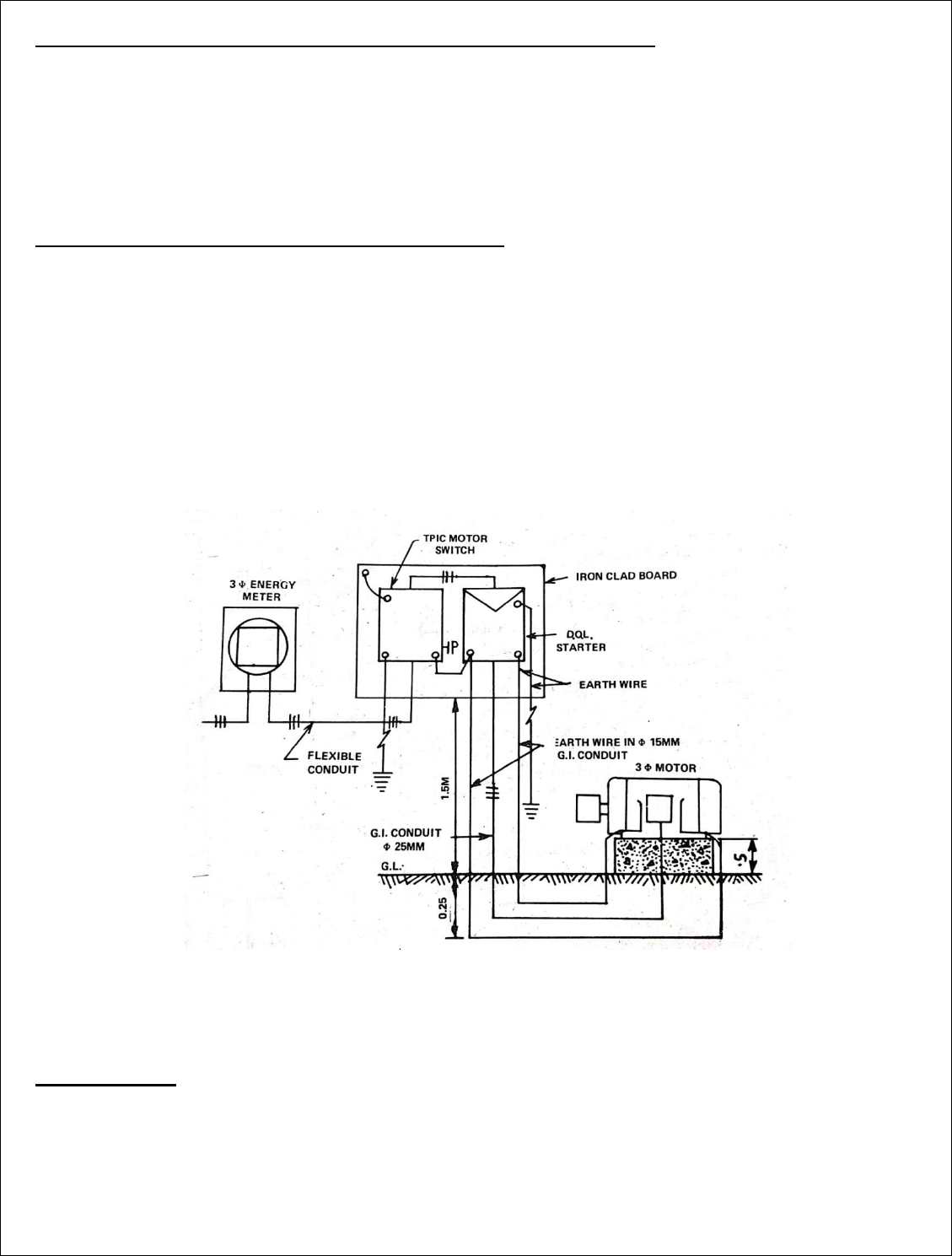
Q.3 It is proposed to install a power connecon of 3 phase 5 HP inducon motor for an
agriculture tube-well in the room of size 3MX3MX3M high. The motor is one metre away
from two nearest walls. Prepare the esmate in the following order.
a) Draw installaon plan showing locaon of MB and motor etc. Also mark path of
wiring by a thick line.
b) Single line diagram. Showing earth wires also.
c) Wiring diagram.
d) Decide the rang and specicaon of important materials and calculate of wire
,conduits,earth wire etc. and prepare a complete list of materials required for wiring

the room with complte specicaon of each item. Also calculate the approximate cost
for the power wiring.
Soluon
Assumpon
a) Total height of main board from oor =1.5 mts
b) Two earth wires enclosed in their respecve 15 mm dia. G.I pipe installed side by side
for earthing the motor.
c) The Motor with pumping set is installed 0.25 mt above oor on a suitable foundaon
Calculaon of load
Running current =
= 9.1 amp say 8 amp
Starng current=1.5 amp
Selecon and rang of MS
It is suggested that a TPIC, Main switch=32 amp,500 volt grade
Selecon and rang of wire
It is suggested that a PVC Insulated aluminium conductor, single core ,660 volts grade of size 6
mm
2
or 1/2.80 mm diameter, should be used for power wiring

Calculaon for length of heavy gauge conduits of 25 mm diameter
From TPIC to motor foundaon=1.5+0.25+1+o.25+0.25=3.25 mts
Taking 10% wastage=0.325mt
Total length of conduit required for wiring the motor =3.25+0.325=3.57 mts say 4 mts
Calculaon for length of heavy gauge conduits of 15 mm diameter
From starter to motor foundaon=(1.5+0.25+1+o.25+0.25)X2=3.25 mts X 2=6.5 mts
Taking 10% wastage=0.65mt
Total length of conduit required for wiring the motor =6.5+0.65=7.1 mts say 7.5 mts
Calculaon for length of exible conduits of 25 mm diameter
From energy meter to main board=1.0 mt
From main switch to starter=0.5 mt
From starter to conduit mouth=0.25mt
From motor foundaon to motor terminal block=0.25mt
Total length of conduit=(1.0+0.5+0.25+0.25)mt=2mt
Taking 10% wastage=0.2mt
Total length of exible conduit required for wiring the motor =2+0.2=2.2mts say 3.25 mts
Calculaon for length of phase wire of 6 mm
2
or 1/2/80 mm dia
From TPIC to motor foundaon=(rigid conduit +exible conduit)X3
=(3.25+2)mts X 3
=15.75 mts
Taking 15% wastage=2.5mt
Total length of phase wire required for wiring the motor=(15.75+2.5)mts=18.25 mt=18.5 mts
Calculaon for length of 8 SWG , G.I , earth wire
From starter to motor foundaon = length of conduit X 2 earth wires
=3.25 X 2 Wires
=6.5 mts
Taking 10% wastage=0.65mt
So total earth wire required for wiring the motor=6.5 +0.65=7.15mt say 7.5 mts
Material Table

Si
no
.
descripon of materials with specicaons
Quanty
1
TPIC main switch 32 amp rang,500 volt
1no.
2
Total length of rigid conduit (25mm dia)
4 mt
3
Total length of exible conduit (25 mm
dia )
2.5 mt
4
Total length of rigid conduit (15mm dia)
7.5
5
Total length of phase wire( 6 mm
2
)
19 mt.
6
Earth wire (14 SWG)
8 mt
7
Saddle
1 pkt
8
Nuts & bolts
1 pkt
9
Wooden screw 20 mm long
30 nos.
10
PVC tape
1 pkt.
11
Bend
30 gms
12
Earthing thimbles 5 amp rang for xing
earth wire to main switch
2nos.
13
Earthing set complete with pipe,earth
wire,charcoal,salt,thimbles,nuts & bolts etc
1 set.

OVER HEAD INSTALLATION
4.1. Main components of overhead lines, line supports, factors Governing Height of pole,
conductor materials, determinaon of size of conductor for overhead transmission line, cross
arms, pole brackets and clamps, guys and stays, conductors conguraons, spacing and
clearances, span lengths, overhead line insulators, types of insulators, lighng arresters,
danger plates, an-climbing devices, bird guards, beads of jumpers, jumpers, tee-os,
guarding of overhead lines.
4.2. Prepare an esmate of materials required for LT distribuon line within load of 100 KW
maximum and standard spans involving calculaon of the size of conductor (from conductor
chart), current carrying capacity and voltage regulaon consideraon using ACSR.
4.3. Prepare an esmate of materials required for LT distribuon line within load of 100 KW
maximum and standard spans involving calculaon of the size of conductor (from conductor
chart), current carrying capacity and voltage regulaon consideraon using ACSR.
4.4. Prepare an esmate of materials required for HT distribuon line (11 KV) within 2 km and
load of 2000 KVA maximum and standard spans involving calculaon of the size of conductor
(from conductor chart), current carrying capacity and voltage regulaon of the size of
conductor (from conductor chart), current carrying capacity and voltage regulaon consider
acon using ACSR.
CHAPTER-4 OVERHEAD INSTALLATION
Q.1 In a city locality, an overhead distribuon line of 400 volts, 3 phase ,50 cycle/sec. is to be
erected along a straight route on steel tubular poles. The length of the line is 500 metres and
the line terminates at the ends. The span between adjacent poles is 50 mts. The street light
conductors are also supported on the same poles.Make a neat sketch of the last 2-3 poles and
esmate the quanty of material required for installing the distribuon line with full
specicaon of each items. Other details of the line are suggested as under.
ACSR conductors are phase lines, neutral and street light conductor of size 6/1
(squirrel conductor). Earth wire 8 SWG , Galvanised iron
Soluon
Assuming that the connecon is taken for the line from an exisng sub-staon of 11/0.4 KV.
Length of line =500 metres
Average span=50 mts.
No. of tubular poles required=
+1=11 nos.
Length of squirrel ACSR conductor of size(6/1 mm)=(500 mts 5)+2% for sag

=2500+50
=2550 mts
In weight=85 kg/km=216.75 kg say 217kg
Length of 8 SWG, galvanized iron= 500+2% for sag
=510 mts
In weight =10 mts/kg=51 kg
Material Table
Si
no
.
descripon of materials with specicaons
Quanty
1
Steel tubular poles (9 mts long)
11 nos
2
ACSR squirrel conductors of size(6/1
mm)
2550 mts(218
kg)
3
E arth conductors 8 SWG GI
510 mts
(51kg)
4
shackle Insulators with ‘D’ straps i.e 5 on
each pole
55 nos.
5
Nuts and Bolts 15 mm dia ,200 mm long with
washers for xing ‘D’ straps with pole,one
for each straps
55 nos.

6
Nuts and Bolts 15 mm dia ,125 mm long
with washers for xing insulators with ‘D’
straps
55 nos.
7
Earth wire pole clamp one on each end pole
2nos.
8
Eye bolts,15 mm dia ,200 mm long for
holding earth wire on intermediate pole
9 nos.
9
Guard wire of size 7/16 SWG ,for guarding at
approximate 15 places
45 mts
10
Reel insulator
15 nos.
11
Pole caps for steel tubular poles
11 nos.
12
Stay wire set complete i.e 2 sets on each
terminals poles
2+2=4 nos
13
Earthing sets complete for earng(one at
each terminal pole and one central pole)
3 sets
14
Street light ng complete with tube and
clamps
11nos.
15
Number plates with clamps
11nos.
16
Pole foundaon for each pole
11nos.
17
To complete the job miscellaneous items
such as cement ,sand, concrete etc
-
18
14 SWG ,galvanized steel wire as binding
wire
5kg
Q.2 A tube well owner wants 3 phase,4 wire power connecon to his 10 BHP motor from
an over head double pole structure having of 25 KVA ,11/0.4 KV . The double pole structure
is 300 metres away from tube well. Esmate the quanty of materials required for erecng
a line and for giving a service connecon to the tube well motor. Also draw neat sketch of
the same.
Soluon
Total connected load =10BHP

Running current=
= 14.07 amp
Starng current=1.5 amp
To meet the present load requirement and Provision for future requirement in the event
expansion of building and any other electrical points in the exisng building =(50%
)+21.10=31.65 amp
It is therefore suggested that
L.T core ,aluminium conductor weather proof cable of size =6 mm
2
(from
distribuon transformer to pole and from last pole to the meter box)
A.A.C of minimum size =3/3.00 mm mans stranded conductor (from rst pole to last
pole)
Average span=50 mts.
No. of Concrete pole required(9 mt. long) =
=6 nos.
Length of mans AAC conductor of size(3/3.00 mm)=(300 mts 4)+2% for sag
=1200+24
=1224 mts
In weight=58 kg/km=70.998kg say 71 kg
Length of 8 SWG, galvanized iron= 300+2% for sag
=306mts
In weight =10 mts/kg=30.6kg

Material Table
Si
no
.
descripon of materials with specicaons
Quanty
1
RCC poles (9 mts long)
6 nos
2
AAC, mans conductors of size(3/3.00mm)
1224
mts(70kg)
3
E arth conductors 8 SWG GI
306 mts
(30.6kg)
4
Shackle Insulators with ‘D’ straps i.e 4 on each
pole
24+4=28 nos
5
Nuts and Bolts 15 mm dia ,200 mm long with
washers for xing ‘D’ straps with pole,one for
each straps
28nos.
6
Nuts and Bolts 15 mm dia ,125 mm long with
washers for xing insulators with ‘D’ straps
28 nos.
7
Eye bolts,15 mm dia ,200 mm long for holding
earth wire on intermediate pole
4 nos.
Earth wire pole clamp one on each end pole
2 nos.
9
Guard wire of size 7/16 SWG ,for guarding at
approximate 15 places
30 mts
10
Aerial fuse,32 amp rang on last pole
3 nos.
11
L.T outdoor cable box, complete with clamps
2 nos.

12
Reel insulator
10 nos.
14
Stay wire set complete i.e 2 sets on each
terminals poles
2+2=4 nos
15
Earthing sets complete for earng
1 sets
16
Number plates with clamps
6 nos.
17
Pole foundaon for each pole
6 nos.
18
To complete the job miscellaneous items such
as cement ,sand, concrete etc
-
19
14 SWG ,galvanized steel wire as binding wire
2kg
Q.3 Esmate the quanty of material required for the construcon of 1 kilometre
overhead line. The line is tapped from the exisng 11 KV line to feed a parcular locality.
The parculars of the important materials to be used for the line to be erected are as
follows.
a) Size of conductor : ACSR 6/1 mm
b) Tubular pole or supports of 11 metres length
c) Size of earth wire : G.S (galvanized steel ) 8 SWG
d) Average span length=100 mts.
e) No. of earthing sets to be installed:3 nos.
Soluon
Total Length of conductors (ACSR weasel conductor 6/1 X 2.59 mm )= (1000X3)+2% for sag
=3000+60=3060 mts
Total length of G.I. earth wire of size 8 SWG =1000+2% for sag
=1000+20=1020 mts

Material Table
Si
no
.
descripon of materials with specicaons
Quant
y
1
Tubular line supports (11 mts long)
10 nos
2
Material required for connecon with exisng line
of 11 KV line
1. M.S channel for cross arm (10 cmX5
cmX1.5mts)
2. H.T ,11 KV Disc insulator with complete
ngs
3. H.T ,11 KV ,pin type insulators with nuts and
bolts
4. Stay complete sets ( clamps ,stay wire, egg
insulators ,stay rod stay bow, stay plates)
5. Earth wire clamp
6. Binding wires
7. Clamps for M.S channel
8. Concreng for stay rod
1no.
3nos.
2 nos.
2nos.
1no.
1 kg
1 no.
2nos.

3
Fing for new line supports
1. Stone pads for poles
2. Angle iron cross arms, 1 for each pole
3. clamps for xing cross arm with poles
4. 11 KV ,pin type insulators with nuts and
bolts
5. No. plates with clamps for xing
6. Danger plates with clamps for xing
7. Earth wire clamp
8. Barbed wire for an climbing for 10 poles @
1 kg
for each pole
9. Binding wires (for xing conductors over
insulators)
10. Stay complete sets ( clamps ,stay wire, egg
insulators ,stay rod stay bow, stay plates)
10 nos.
10 nos.
10 nos.
30 nos.
10 nos.
10 nos.
10 nos.
10kg
6kg
2nos
4
ACSR weasel conductors of size 6/1 X 2.59 mm
3060
mts
5
G.I earth wire of size 8 SWG
1020
mts.
6
Earthing complete sets (G.I pipe, charcoal ,salt etc)
3 nos.
7
Painng for poles
10 nos.
Q.4 Esmate the material and cost for the construcon of 1 kilometre overhead line. The
line is tapped from the exisng 11 KV overhead line. Assuming that the line is passing over
the main road, telegraph line and railway line. Given data:
a) Size of conductor : ACSR 6/1 mm gopher
b) Type of pole : R.S ( Rolled steel ) joist 10 mts and 11.5 metres long.
c) Size of earth wire : G.S (galvanized steel ) 8 SWG
d) Type of cross arm : mode of angle iron
e) No. of earthing : plate eathing
Soluon

Total Length of conductors (ACSR gopher conductor 6/1 X 2.36 mm )= (1000X3)+2% for sag
=3000+60=3060 mts
Total length of G.I. earth wire of size 8 SWG =1000+2% for sag
=1000+20=1020 mts
Material Table

Si
no
.
descripon of materials with specicaons
Quanty
1
a) R.S joist poles 15cm diameter 10 mt
long
b) R.S joist poles 15cm diameter 11.5 mt
long
6 nos.
6 nos.
2
Material required for connecon with exisng
line of 11 KV
a) M.S channel for cross arm (10 cmX5
cmX1.5mts)
b) H.T ,11 KV Disc insulator with complete
ngs
c) H.T ,11 KV ,pin type insulators with nuts
and bolts
d) Stay complete sets ( clamps ,stay wire,
egg insulators ,stay rod stay bow, stay
plates)
e) Earth wire clamp
f) Binding wires
g) Clamps for M.S channel
h) Concreng for stay rod
1no.
3nos.
2 nos.
2nos.
1no.
1 kg
1no.
2nos.
3
Fings for new line supports
a) Stone pads for poles
b) Angle iron cross arms, 1 for each pole
c) clamps for xing cross arm with poles
d) 11 KV ,pin type insulators with nuts and
bolts
e) No. plates with clamps for xing
f) Danger plates with clamps for xing
g) Earth wire clamp
h) Barbed wire for an climbing for 10
poles @ 1 kg
for each pole
i)Binding wires (for xing conductors over
insulators)
12 nos.
12 nos.
12nos.
42 nos.
12 nos.
12 nos.
12 nos.
12 kg
8 kg
4
Extra material for poles at road crossing
a) Brindling cross arm
b) Cross arm clamps
2 nos.
2nos.

c) Guard wire
d) Eye bolts for holding guard wire
25 kg
6 nos
5
Extra material for telegraph line crossing
a) Cross arm
b) Clamps for cross arm
c) Guard wire
d) Eye bolts for holding guard wire
2nos.
2 nos.
25 kg.
6 nos
6
Extra material for rail way line crossing
a) Cross arm
b) Clamps for cross arm
c) Guard wire
d) Eye bolts for holding guard wire
2nos.
2 nos.
25 kg.
6 nos
7
ACSR gopher conductors of size 6/1 X 2.36
mm
3060 mts
8
G.I earth wire of size 8 SWG
1020 mts.
9
Earthing complete sets (G.I pipe, charcoal
,salt etc)
4 nos.
10
Painng for poles
12 nos.

OVER HEAD SERVICE LINES
5. 1 Components of service lines, service line (cables and conductors), bearer wire, lacing rod.
Ariel fuse, service support, energy box and meters etc.
5. 2 Prepare and esmate for providing single phase supply of load of 5 KW (light, fan, socket)
to a single stored residenal building.
5. 3 Prepare and esmate for providing single phase supply load of 3KW to each oor of a
double stored building having separate energy meter.
5. 4 Prepare one esmate of materials required for service connecon to a factory building
with load within 15 KW using insulated wire.
5. 5 Prepare one esmate of materials required for service connecon to a factory building
with load within 15 KW using bare conductor and insulated wire combined.
CHAPTER -5 OVERHEAD SERVICE LINE
PREPARE AND ESTIMATE FOR PROVIDING SINGLE PHASE SUPPLY LOAD OF 5KW
(LIGHT,FAN,SOCKET) TO A SINGLE STORED RESIDENTIAL BUILDING
Q.1 A newly constructed single storeyed house is to be provided with single phase 230
volts,50 HZ having a load of 5 KW(light,fan,socket). The supply is to be given from overhead
line 20 mt. away from the building. Prepare a list of the material,for giving sevice
connecon and also esmate the cost of the service connecon. A G.I pipe is to be raised
along the roof to receive bare conductor on its cross arm ed with insulators. Also draw
sketch of service connecon.
Soluon
Assumpons
1. Height of ground oor=3.5 mts.
2. Service connecon received at the height of 6 mts. from ground.
Selecon and rang of weatherproof ,twin core, aluminium conductor cable and line
conductor
Total connected load=5 KW
Total load in ampere=5000/230=21.7 amp
Diversity factor=60%X21.7=13 amp
To meet the present load requirement and Provision for future requirement in the event
expansion of building and any other electrical points in the exisng building =(50%
X13)+13=19.5 amp
It is therefore suggested that

Rang of weatherproof cable =6 mm
2
or 1/2.80 mm ,twin core, PVC insulated cable to
carry a load current of 27 amp.
Rang of bare conductor for installaon between distribuon pole upto insulators=10
mm
2
,AAC
Rang of earth wire=8 SWG
Material Table
Si
no
.
Specicaon
Quanty
1
PVC weatherproof cable of size 6mm
2
or
1/2.80 mm twin core including wastage
10mts
2
AAC for phase and neutral connecon (10
mm
2
)
42 mts
3
8 SWG GI earth wire(from pole to meter
board)
20+1+10=3
1 mts
4
G I pipe (50 mm diameter)
8mt.
5
Conduit bends
3 nos
6
GI pipe Saddles
10 nos.
7
Earthing Thimble (to x earth wire and stay
wire)
2 nos.
8
LT shackle insulators
4 nos.
9
Angle iron bracket insulator of
size(50mmX50mmx6mmx60mm) long
2 nos.
10
Stay insulator
1no.
11
Stay wire
7mt.

12
Stay bow
1 nos
13
Stay rod
1 nos
14
Cement
1 bag
15
Sand
3 bag
16
Concrete
2 bag
17
2 Way juncon box
2 nos.
18
Nuts & bolts
2 pkt
Q.2 A newly constructed single storeyed house is to be provided with single phase 230
volts,50 HZ having a load of 4 KW. The supply is to be given from overhead line 30 mt. away
from the building. Prepare a list of the material,for giving sevice connecon and also
esmate the cost of the service connecon.
Soluon
Assumpons
3. Height of ground oor=3.5 mts.
4. Service connecon received at the height of 6 mts. from ground.
Selecon and rang of weatherproof ,twin core, aluminium conductor cable
Total connected load=4 KW
Total load in ampere=4000/230=17.29 amp
Diversity factor=60%X17.29=10.43 amp

To meet the present load requirement and Provision for future requirement in the event
expansion of building and any other electrical points in the exisng building =(50%
X10.43)+10.43=15.21 amp
It is therefore suggested that
Rang of weatherproof cable =4 mm
2
or 1/2.24 mm ,twin core, PVC insulated cable
Rang of G.I wire=8 SWG
Material Table
Si
no
.
specicaon
quanty
1
PVC weatherproof cable(from pole to EM
with wastage)
30+2+15=4
7 mt
2
8 SWG GI wire
32 mt.
3
G I pipe (50 mm diameter)
8mt.
4
Conduit bends
3 nos
5
GI pipe Saddles
10 nos.
6
Earthing Thimble
2 nos.
7
Stay wire
7mt.

8
Stay insulator
1 nos
9
Stay bow
1 nos
10
Stay rod
1 nos
11
Cement
1 bag
12
Sand
3 bag
13
Concrete
2 bag
14
2 Way juncon box
2 nos.
15
Nuts & bolts
2 pkt
16
Binding wire
2 mts
PREPARE AND ESTIMATE FOR PROVIDING SINGLE PHASE SUPPLY LOAD OF 3KW TO EACH
FLOOR OF A TO DOUBLE STORED RESIDENTIAL BUILDING HAVING SEPARATE ENERGY METER
Q.3 Prepare a list of material and esmate the cost for giving service connecon to a
double storeyed building having two energy meters.The supply is to be given at 230 volt
single phase having a load of 4 sub-cicuit (light,fan )and two 15 amp socket points on each
oor .The supply is to be given from overhead line 20 metres away from the building .Also
draw diagram of service connecon.

Soluon
Assumpons
1. Height of ground oor=3.5 mts.
2. Total height of rst oor from ground=7mts.
3. Service connecon received at the height of 6 mt. from ground.
4. Height of ground oor meter board from oor=1.5mts.
Selecon and rang of weatherproof ,twin core, aluminium conductor cable and Line
conductor
Total connected load for 4 sub-circuit=4X800=3200 was
2-15 amp sockets=2X1000=2000was
So total load of a single building storeyed=3200+2000=5200 wa
Total load in ampere=5200/230=22.6amp (for single storeyed )
Total connected load for both oor=22.6+22.6=45.2 amp
Diversity factor=60%X45.2=27.12amp

To meet the present load requirement and Provision for future requirement in the event
expansion of building and any other electrical points in the exisng building .It is therefore a
beer suggeson that a weather proof cable of higher rang may be used=(50%
X27.12)+27.12=40.68amp
It is therefore suggested that
Rang of weatherproof cable =16 mm
2
or 7/1.70 mm ,twin core, PVC insulated cable
Rang of bare conductor for installaon between distribuon pole upto insulators=16
mm
2
ACSR Conductor
Rang of G.I wire=8 SWG
Material Table
Si
no
.
Specicaon
Quanty
1
Shackle insulators with U clamps,nuts & bolts
2+2=4 nos.
2
Mild steel channel or hook
2 nos.
3
ACSR conductor for phase and neutral
connecon (16mm
2
) including wastage
20+20+2=42
mts
4
8 SWG GI earth wire(from pole to meter boa)
20+1+15=36
mts
5
MS angle iron bracket of
sze(50mmX50mmx6mmx1mt) long
2 nos.
6
PVC Weather proof cable
15 mt
7
MS Saddles
15 nos.
8
Earthing Thimble (to x earth wire )
2 nos.
9
Reel insulator
1no.
10
Guard wire
7mt.
11
Cement
1 bag
12
Sand
3 bag
13
2 Way juncon box
2 nos.
14
Nuts & bolts
2 pkt

PREPARE ONE ESTIMATE OF MATERIAL REQUIRED FOR SERVICE CONNECTION TO A
FACTORY BUILDING WITH LOAD WITHIN 15KW USING INSULATED WIRE
Q.1 A workshop required to connect a 3-phase 15 KW ,415 V ,50 HZ motor to a 3-phase ,4-
wire,415/240 volt ,50 HZ overhead line .The distance of the service line from the workshop
structure having motor is 15 mt. The motor has an eciency of 85% and a power factor of
0.8 . Esmate the quanty and cost of material required.
Soluon
Assumpons
1. Height of ground oor=6 mts.
2. Service connecon received at the height of 7 mts. from ground.
Selecon and rang of weatherproof ,twin core, aluminium conductor cable
Total connected load =15KW
Running current=
=30 amp
Starng current=1.5 amp
Diversity factor =60%
To meet the present load requirement and Provision for future requirement in the event
expansion of building and any other electrical points in the exisng building =(50%
)+27=40.5 amp
It is therefore suggested that
Rang of weatherproof cable =10mm
2
or 1/3.55 mm ,4 core, PVC insulated aluminium
conductor
Rang of G.I wire=8 SWG

Material Table
Si
no
.
specicaon
quanty
1
PVC weatherproof cable(from pole to EM
with wastage)
15+2+5+10
=32mt
2
8 SWG GI wire
17 mt.
3
G I pipe (50 mm diameter)
7mt.
4
Conduit bends
3 nos
5
GI pipe Saddles
15 nos.
6
Pole clamp
1 nos
7
Cement
1 bag
8
Sand
3 bag
9
Concrete
2 bag
10
2 Way juncon box
2 nos.
11
Nuts & bolts
2 pkt
12
Binding wire
2 mts
13
M S hook
1 no.

Q.2 A workshop owner wants 3-phase ,4 wire power connecon to his 10 HP motor from
the pole of 400v ,3 phase 50 HZ overhead line at a distance of 200mt. from the workshop.
Make a sketch showing the arrangement of supply and esmate the quanty and cost of
the material required.
-
Soluon
Assumpons
1. Height of ground oor=6 mts.
2. Service connecon received at the height of 7 mts. from ground.
Selecon and rang of weatherproof ,twin core, aluminium conductor cable
Total connected load =10HP
Running current =
= 15.8 amp
Starng current=1.5 amp
To meet the present load requirement and Provision for future requirement in the event
expansion of building and any other electrical points in the exisng building =(50%
)+23.7=35.55 amp
It is therefore suggested that
Rang of weatherproof cable =6 mm
2
or 1/2.80 mm ,4 core, PVC insulated aluminium
conductor
Rang of bare conductor for installaon between distribuon pole upto insulators=10
mm
2
ACSR Conductor
Rang of G.I wire=8 SWG
Material Table
Si
no
.
specicaon
quanty
1
PVC weatherproof cable
15 mts
2
Bare conductors
808 mts
3
Shackle insulator
8 nos.
4
8 SWG GI wire
202 mt.

5
G I pipe (50 mm diameter)
6 mt.
6
Conduit bends
3 nos
7
GI pipe Saddles
15 nos.
8
Earthing Thimble
2 nos.
9
Cement
1 bag
10
Stay insulator
1no.
11
Stay wire
7mt.
12
Stay rod
1 nos
13
Stay bow
1 nos
14
Reel insulator
2no.
15
Guard wire
8mt.
16
Sand
3 bag
17
Concrete
2 bag
18
2 Way juncon box
2 nos.
19
Nuts & bolts
2 pkt
20
Binding wire
2 mts

ESTIMATING FOR DISTRIBUTION SUBSTATIONS
6. 1 Prepare one materials esmate for following types of transformer substaons.
6.1.1 Pole mounted substaon.
6.1.2 Plinth Mounted substaon.
CHAPTER -6 ESTIMATING FOR DISTRIBUTION SUBSTATION
Q.1 Esmate the cost of a pole mounted sub-staon of capacity 50 KVA transformer of
rang 11/0.4 KV. The H.T line is available about 50 metres from the proposed site.Also make
a neat sketch of the pole mounted sub-staon.
Soluon
Total Length of conductors (ACSR gopher conductor 6/1 X 2.36 mm )= (50X3)+2% for sag
=150+3=153 mts
Total length of G.I. earth wire of size 8 SWG =50+2% for sag
=50+1=51 mts.

Material Table
Si
no
.
descripon of materials with specicaons
Quant
y
1
Material for H.T connecon with main line
1. M.S channel cross arm 10 cm 1.5 mt
long
2. H.T ,11 KV Disc insulator with complete ngs
3. Stay complete sets ( clamps ,stay wire, egg
insulators ,stay rod stay bow, stay plates)
4. Earth wire clamp
5. Binding wires
6. Clamps for M.S channel
7. Concreng for stay rod
1no.
3nos.
2 nos.
2nos.
500
gms
1 no.
2nos.

2
Conductor ACSR gopher 6/12.36 mm diameter
153
mts.
3
Earth conductors 8 SWG GI
51 mts.
4
R .S joist 175 mm 10 mt long
2 nos.
5
Fings on H.T double pole structure for pole
mounted sub-staon.
1. Stone pad
2. Sub-staon plate
3. M.S channel cross arm 100 mm
2.65mt long
4. Eye bolt
5. Dropper angle iron 75 mm
2mt long
6. Stay complete sets
7. 11 KV ,Disc type insulators with nuts and bolts
8. Binding wires
11. No. plates with clamps for xing
12. Danger plates with clamps for xing
13. Earth wire clamp
14. Barbed wire
15. Earthing complete
16. Jumper wire for jumping
17. Nuts and bolts of size as required.
18. Concreng poles
19. T.P.M.O switch
20. Painng of pole and other aachments
21. Fuse sets
2 nos.
1 no.
1no.
3 nos.
6no.
4 nos.
3nos.
500
gms
1no.
1no.
1no.
5kg.
1set
11mts
18nos.
2 nos
1no.
2 litres
1set
6
Transformer 50 KVA ,11/0.4 KV
1no.
7
TPICN(triple pole iron clad with neutral ) main switch
100 ampere rang
1no.
8
Earthing for transformer
1no.
9
Lighng arresters one set of three
1set


