
GMP ANNEX 1 DRAFT (VERSION 12)
IMPLEMENTATION TIMING EXAMPLE 4.23
25May2021 1 | P a g e
Implementation Example for the Requirement of Barrier Technology (Isolator and
Restricted Access Barrier Systems, RABS) and Barrier Glove Integrity Testing (section 4.23)
Context:
This is one of several examples that have been developed by different industry associations to help
inform the IWG as to the levels of complexity these types of changes can have as they consider
Annex 1 implantation timing. The examples provided are from the top 5 requirements identified in
the letter from the Annex 1 Associations’ Coordination Meeting Team dated 14 March 2021 and
have been developed as if the requirements in the revised EU GMP Annex 1 draft (version 12) were
to be included in the final Annex 1 revision as currently written. As such they do not take into
consideration any changes made to the current draft version of Annex 1.
The examples are intended to be informative only and as such were not taken through a consensus
process across the associations. They should not be considered as industry guidance on
implementation approaches or specific timing. It is important to stress that each individual
situation, in regard to implementation, will in most cases be unique based on process, product, and
facility differences and taking into account the Contamination Control Strategy outcomes. As such,
this specific example is not meant to provide an industry vetted acceptable path or guidance to
achieve an acceptable path to compliance with the requirements noted in section 4.23.
It is important to note that these examples are not intended to imply agreement with the revised EU
GMP Annex 1 draft (version 12) as written, as reflected in the industry comments submitted in the
2020 targeted consultation.

GMP ANNEX 1 DRAFT (VERSION 12)
IMPLEMENTATION TIMING EXAMPLE 4.23
25May2021 2 | P a g e
This example focuses on the challenges resulting from implementation of revised EU GMP Annex 1
draft (version 12) relating to the requirement of integrity testing of barrier technology; Isolators and
RABS together with associated barrier gloves.
Annex 1 Requirement:
4.23
“The materials used for glove systems (for both RABS and isolators), as well as other
parts of an isolator, should be demonstrated to have good mechanical and chemical
resistance. Integrity testing of the barrier systems, and leak testing of the glove system
and the isolator should be performed using a methodology demonstrated to be suitable
for the task and criticality. The testing should be performed at defined periods, at a
minimum at the beginning and end of each batch, and should include a visual inspection
following any intervention that may affect the integrity of the system. For single unit
batch sizes, integrity may be verified based on other criteria, such as the beginning and
end of each manufacturing session. RABS gloves used in Grade A zone should be
sterilized before installation and sterilized (or effectively decontaminated by a validated
method which achieves the same objective) prior to each manufacturing campaign. The
frequency of glove replacement should be defined within the CCS.”
Considerations and Impact of Requirement 4.23; Barrier and Glove Integrity Testing:
Considering the principal requirement of Annex 1 regarding; 4.23 ‘’Integrity testing of the barrier
systems, and leak testing of the glove system and the isolator should be performed using a
methodology demonstrated to be suitable for the task and criticality’’ there are developed integrity
test technologies for barriers and gloves. Currently, however, not all barrier technology systems
have integrated integrity testing and In some cases, further development is required to meet the
required sensitivity/ detectability.
The criticality of the ‘barriers’ physical separation of Grade A to surrounding environment, where
operators are present, should be considered as one of the contamination control attributes that
enable Grade A conditions to be established within a defined boundary. The physical integrity of the
barrier needs to be maintained within set limits to mitigate risks of Grade A compromise.
To maintain this level of control the leak integrity test method must have the required sensitivity
and in the process of test execution not put undue stress on the barrier that may by default cause an
integrity failure. Barrier leak integrity levels may also need to meet requirements of safety including
a greater integrity if processing toxic or highly potent products and for Isolators (and in some cases
Closed RABS systems) to contain hydrogen peroxide vapour or other bio-decontamination agents.
Further, considering 4.23 ‘’The testing should be performed at defined periods, at a minimum at the
beginning and end of each batch, and should include a visual inspection following any intervention
that may affect the integrity of the system’’. In a production setting barrier and glove integrity
testing requires integration into the barrier environmental control system so automated (non-
intrusive) leak integrity testing can be completed, typically by a pressure decay method over a short
(rapid) test period so the impact of temperature and barometric changes are mitigated.
More manual, intrusive leak integrity tests may be appropriate at factory qualification testing of
barrier systems or at IQOQ qualification stages. For routine process monitoring a qualified integrity
test system requires integrated control and non-intrusive application of pressurising sources
together with control to reach target test pressure set-points, allow stabilisation and monitoring of

GMP ANNEX 1 DRAFT (VERSION 12)
IMPLEMENTATION TIMING EXAMPLE 4.23
25May2021 3 | P a g e
pressure decay over a set decay period with a clear determination of ‘pass – fail’ result. In addition
integrity test result reporting that meets requirements of data integrity is expected.
Leak integrity testing of barrier gloves requires different strategies for Isolators and RABS but if
tested in-place on the barrier Glove ports require to be closed/ sealed via a test cover that has the
appropriate level of integrity so risks of false failure (inferred integrity failure) are mitigated. In
these cases, the glove-sleeve, glove port and glove integrity test system (glove port sealing device)
are a combined system.
Currently not all glove ports have a suitable method to close and seal the glove port so a glove
integrity test can be completed. Alternatively the glove integrity test system provided does not have
the required detectability or appropriate qualification methodology – more development is
required. For production scale modern Isolator systems wireless Lan automated Glove integrity test
systems are developed that meet Pharma 4.0 levels of control connectivity, reporting and data
integrity management but it is not expected this ‘gold standard’ would apply to all applications. For
each case, requirements of criticality, functionality, detectability and robustness need to be
considered.
Considering the requirement; ‘’barrier gloves used in RABS Grade A zones should be sterilized before
installation. For RABS barrier gloves that may be exposed to the background environment during
operation, disinfection using an approved methodology following each exposure should be used’’.
In this case RABS gloves integrity testing, both visual and physical, should be completed before
sterilisation and installation into the barrier system together with, as a minimum, visual inspection
for defects on a daily basis during operations. Based on risk assessment, RABS gloves may also be
physically integrity tested in-place with a suitable methodology.
If this is the case then RABS glove ports and compatible glove integrity test systems may need
installation as a compatible system set replacing existing glove ports that are not suitable to connect
a glove integrity tester.
For testing barrier glove integrity in-place there is a limit of detection of 100-micron pin-hole size
within the glove material. During integrity testing via pressurisation and monitoring of pressure
decay it follows that contamination may be introduced via the pin hole if the glove-sleeve is
pressurised into the Grade A zone. For Isolators, this contamination risk is typically mitigated by leak
integrity testing gloves before the vapourised hydrogen peroxide (VHP/vH202) Bio-decontamination
cycle (or other automated disinfection method) and after batch production so the Grade A
environment is not compromised during processing of sterile products.
For campaigns where glove integrity testing may be required mid batch there is available glove
integrity test systems that pressurise the barrier glove outwards so any loss of integrity does not
introduce contamination into the Grade A zone. Not all Isolator manufacturers have developed this
‘Campaign Glove testing’ technology and further development may be required.
Implementation Times for Integrity Testing of Barrier Technology and Gloves:
This example justification is meant to illustrate where and why additional implementation time may
be needed for barrier technology and glove integrity testing.
Based on the considerations for barrier and glove integrity testing the following technical changes
may be required, in-part or all depending on how advanced the barrier technology may be.

GMP ANNEX 1 DRAFT (VERSION 12)
IMPLEMENTATION TIMING EXAMPLE 4.23
25May2021 4 | P a g e
Barrier leak integrity testing – potential technical changes to meet intent of Annex 1
• Change of Isolator control system may be required (software or control boards) to facilitate
an automated pressure decay test of the barrier technology. Typically applies to Isolators
(with Grade D or C background) or in some cases to Closed RABS systems with a Grade B
background that apply integrated Gaseous bio-decontamination e.g. VHP/ vH202. This case
the Closed RABS would require barrier leak integrity testing to assure safe containment of
VHP/vH202.
• To execute a pressure decay test the barrier system must be closed, including any air make
up of extract paths used for air exchange/ pressure control within the Isolator/ barrier.
Automated dampers may be required or for simpler isolators closing plates fitted to seal the
air pathway that provide the required level of robust ‘dynamic’ sealing integrity.
• To control the test pressure to a starting point around which acceptance criteria in pressure
decay may be set, compressed air introduction may be required as the control of Isolator fan
ventilators may be inadequate (not sensitive enough).
• The leak integrity test pre-production as a GMP control measure may need combining as a
safety measure for containment if VHP/vH202 is specified. In this case the leak test is also a
safety measure to mitigate risks of advancing to ‘gassing’ if there is an integrity failure. The
Isolator control system needs to accommodate these combined requirements.
Glove leak integrity testing – potential technical changes to meet intent of Annex 1
• Change of glove ports on the barrier technology to facilitate integration of a compatible
Glove integrity test system with the required level of sealing so pressure decay results focus
on the integrity of the glove (not the test device).
• If it is not possible to replace the glove ports in the barrier panel to facilitate integration of a
compatible glove test system the combined barrier panel (vision panel, glass or plastic) and
new glove port systems will require replacement.
• Optimization of the control sequence recipe used for glove integrity testing may be required.
Automated pressure decay tests are typically applied as rapid tests over a short period to
negate any impact from temperature and barometric change over time. Before pressure
decay results can indicate a glove integrity issue there must be a stabilization period that
allows for any test impact from glove stretching and temperature (as result of energy in
pressurization), to prevent false failures. Volume changes due to glove stretching or pressure
changes e.g. from cooling = negative pressure change and heating = positive pressure
change can provide false pass or fail results. Stabilization time needs development and
optimization to accommodate inherent process variables as different glove materials have
different stretch characteristics.
• Efficient glove integrity test systems have a limit of detection of 100-micron hole sizes that
are typically not detected by visual inspection (VI) alone (VI has a limit of detection around
400-500 micron). To achieve this level of sensitivity-detectability test pressures require to be
over 500 pascal and in many cases are typically applied around 1000 pascal. If current glove
integrity test systems have inadequate test pressures and an optimized control sequence

GMP ANNEX 1 DRAFT (VERSION 12)
IMPLEMENTATION TIMING EXAMPLE 4.23
25May2021 5 | P a g e
recipe of stabilization further development of the glove integrity test system may be
required.
All technical changes will take time and together with qualification will extend implementation time.
As process improvements and keeping up to date with current technology are an expectation there
may be a need to develop an implementation plan for improvements and this plan may take
extended time to execute without unduly impacting production operations and capacity output
(medicine supplies).
Example of Project Implementation Activities:
The following example is intended to illustrate the types of activities and associated timing for
implementation of barrier and glove integrity testing:
Activity list:
Project step
Comment
Technology Development
Required where the current technology is not available to meet
the technical (sensitivity) or operational requirements. Timing is
depended on the development of technology.
Receipt of purchase order (PO)
Before project start there is a project team alignment and Kick off
Technology integration schematics
and controls/ automation strategy
Combined integration of barrier technology, barrier integrity test
and glove integrity test technology.
Design reviews – risk assessment
schematics/ automation strategies
Joint meetings with site and Isolator/ integrity test technology
manufacturers.
Detail Design & reviews
Review of barrier integrity test design integration.
Glove integrity test Technology
manufacturing & FQT
Each specialist manufactures technology followed by Factory
Qualification Testing (FQT) and Factory Acceptance Testing (FAT)
to be integrated onto barrier technology. Site representatives
attend with FAT focusing on functionality (detectability and
sensitivity).
Manufacture of sub-system parts for
barrier integrity testing integration
Sub-systems (that can be) pre-installation tests of functionality.
Packaging for shipment to site &
delivery
Delivery times and packaging vary depending on transport method
and global location of site.
Installation at site
Involves specialist personnel from barrier technology/ glove
integrity test system manufacturer. Timing based on facility
availability and allowable shutdown timing in regards to product
supply.
Commissioning
Involves specialist teams from barrier technology manufacturer
Technology Qualification, Site
Acceptance Testing (SAT), IQOQ, &
PQ
Involves specialist teams from barrier technology manufacturer.
For glove integrity testing qualification a reference leak challenge
(at limit of detection) needs to be implemented with clear
indications of integrity failure.
Technology user training
Both classroom and Hands on training
Quality oversight and approvals
Sufficient time needed for quality reviews and approvals
Hand over to end user including all
supporting documentation
Formal process to verify completion of all deliverables

GMP ANNEX 1 DRAFT (VERSION 12)
IMPLEMENTATION TIMING EXAMPLE 4.23
25May2021 6 | P a g e
Site progresses to process platform
Qualification
Preparation of all procedural
controls (SOPs)
Could be completed through the project but requires finalisation
before process operations trainings
QA/ QC oversight and approvals
Sufficient time needed for quality reviews and approvals
Regulatory Submissions
Complexity will be dependent on the specifics of the change and
impact
Supportive data package completion
QA/QC/Production activity
GMP inspection
Interim GMP inspections may be required, depends on site history
Regulator Q&A and Approvals
Timing will vary based on the number and specific countries where
submissions are required.
Example Timeline: Optimized
The timeline for each specific project will be determined based on many factors. The intent of the
timeline provided is to provide a general idea of the activities and timing with optimized project
steps that follow in sequence. Figure (1) presents a sequence of events based on the above
description, with some illustrative timelines. These timelines may require modification of timing
depending on implementation complexity and study results.
Figure 1
Summary:
Although barrier and glove integrity testing technologies are developed at a suitable level of
functionality (rapid test) and detectability/ sensitivity not all barrier technology manufacturers have
integrity test technology at the required level of functionality/ detectability so technology
development/ process improvement may be required to meet the full intent of draft Annex 1.
Current barrier technology, in some cases, may not have integrated barrier integrity and/or glove
integrity test technology so integration of current technology onto the barrier may be required.
For barrier technology (Isolators and Closed RABS that apply VHP/vH202 or alternative automated
bio-decontamination processes) both mechanical changes to the barrier and software/ control board
changes may be required to implement an integrated barrier leak integrity test for use during
production operations (before and end of batch, minimum).
Where in-place glove integrity test technology is required there may be a need to replace existing
glove ports (or as assembly with vision panel) to facilitate use of a compatible glove integrity test
technology (as an integrated test system).
Technology Development if Required
(Development outcome dependent)
Integration Strategy/Detailed Design
Equipment Fabrication/Suppler Testing
(Dependent on extent of development)
FQT/FAT of Glove integrity test systems and
Sub components for barrier integrity test
Pack/Shipping/Receipt
(Location Dependent)
Receipt and Installation
(contingent on barrier technology availability)
Optimization; Recipe development
Qualification
(Line time/test material availability)
Regulatory Submissions/Q&A/Approvals
(Global)
16 – 18 Months
12 – 16 Months
3 – 36 Months
*
*
An estimated time for this activity can not be determined as it is contingent on the status of current development at the
specific barrier technology and glove integrity test system manufactures.
Possibly during shutdowns

GMP ANNEX 1 DRAFT (VERSION 12)
IMPLEMENTATION TIMING EXAMPLE 4.23
25May2021 7 | P a g e
Following integrity test technology selection an implementation plan will be required and prepared
case by case to align project requirements and regulatory expectation. The implementation plan will
be referenced in the CCS that will evolve through the product life cycle as continuous improvements
are implemented.
Conclusion:
Including the required regulatory approvals, the implementation of suitable (criticality dependent)
barrier and glove integrity testing could require 3+ years if current technology integration is required
(case specific). Where a significant level of integrity test technology development is required longer
timelines are expected.

GMP ANNEX 1 DRAFT (VERSION 12)
IMPLEMENTATION TIMING EXAMPLE 5.5 and 8.12
25May2021 1 | P a g e
Implementation Example for the Requirement of Sterilization of In-direct Product
Contact Parts (section 5.5 and 8.12)
Context:
This is one of several examples that have been developed by different industry associations to help
inform the IWG as to the levels of complexity these types of changes can have as they consider
Annex 1 implantation timing. The examples provided are from the top 5 requirements identified in
the letter from the Annex 1 Associations’ Coordination Meeting Team dated 14 March 2021 and
have been developed as if the requirements in the revised EU GMP Annex 1 draft (version 12) were
to be included in the final Annex 1 revision as currently written. As such they do not take into
consideration any changes made to the current draft version of Annex 1.
The examples are intended to be informative only and as such were not taken through a consensus
process across the associations. They should not be considered as industry guidance on
implementation approaches or specific timing. It is important to stress that each individual
situation, in regard to implementation, will in most cases be unique based on process, product, and
facility differences and taking into account the Contamination Control Strategy outcomes. As such,
this specific example is not meant to provide an industry vetted acceptable path or guidance to
achieve an acceptable path to compliance with the requirements noted in sections 5.5 and 8.12.
It is important to note that the examples developed are not intended to imply agreement with the
revised EU GMP Annex 1 draft (version 12) as written, as reflected in the industry comments
submitted in the 2020 targeted consultation.

GMP ANNEX 1 DRAFT (VERSION 12)
IMPLEMENTATION TIMING EXAMPLE 5.5 and 8.12
25May2021 2 | P a g e
This example focuses on the challenges resulting from implementation of the revised Annex 1 draft
(version 12) relating to the requirement of sterilization of in-direct product contact parts sections 5.5
and 8.12.
Annex 1 Requirement:
5.5
“Direct and indirect contact parts should be sterilized. Direct contact parts are those that
the product passes through, such as filling needles or pumps. Indirect product contact
parts are equipment parts that come into contact with sterilized critical items and
components”
8.12
“For sterile products that cannot be filtered, the following should be considered:
i. All product and component contact equipment should be sterilized prior to use.”
Sterilization of In-direct Contact Parts:
Section 5.5 is clear in stating direct and in-direct product contact parts should be sterilized.
Sterilization in context would be considered as a process documented in pharmacopeia as a
penetrative process e.g., moist heat, dry heat, gamma and ETO. For direct product contact parts this
is an accepted practice.
However due to complexities in process operations within Isolator barrier technology, over the
years, different practices have been applied to in-direct product contact surfaces that are
impermeable stainless steel surfaces and are considered suitable for surface sterilization. In some
cases the method of ‘surface sterilization’ that is applied in vaporized hydrogen peroxide vH
2
0
2
/VHP
based on the claim 6log+ sporicidal efficacy of surfaces can be achieved.
The regulatory concern around the Fragility of vH
2
0
2
/VHP because of the limitations of penetration
to protective or high density bioburden layers (including spore clumps) as exhibited in ‘Rogue BI’
biological indicator unexpected growth within a qualified bio-decontamination cycle has put the use
of vH
2
0
2
/VHP as a surface sterilization method into question. Further there is no reference to
vH
2
0
2
/VHP as a sterilization process in pharmacopeia or differentiation between penetrative
sterilization and ‘surface sterilization’.
It is understood the regulatory expectation for compliance to Annex 1 is that direct and in-direct
product contact parts are sterilized and by default, sterilization would be a pharmacopeia recognized
process.
As vH
2
0
2
/VHP is not a recognized pharmacopeia sterilization process and although there are other
references e.g., USP guidance, that defines vH
2
0
2
/VHP as a sterilization process. When considering
Annex 1 compliance, USP claims for this type of ‘surface sterilization’ process executed within barrier
technology may not be justified to fully meet the intent of Annex 1, particularly if bioburden control
and qualifications fall short of expectations.
In the case where vH
2
0
2
/VHP cycle is applied as the only bio-decontamination process for the barrier
and process equipment non-product contact surfaces and in the same cycle ‘surface sterilization’ of
in-direct product contact parts this would have to be justified using QRM principles.
Such principles would need to recognize the different requirements for cleaning and bioburden
control for bio-decontamination of non-product-contact process equipment/ barrier surfaces and
‘surface sterilization’ of in-direct product contact surfaces.

GMP ANNEX 1 DRAFT (VERSION 12)
IMPLEMENTATION TIMING EXAMPLE 5.5 and 8.12
25May2021 3 | P a g e
Practice of Assuring Sterility of In-direct Product Contact Parts in Barrier Technology:
In filling lines, in-direct product contact parts e.g. container closure feeder bowls, bowl loading guide
chutes, track ways and insert devices are managed differently for RABS and Isolator barriers.
Typically in Open RABS systems in-direct product contact systems are sterilized out-of-place (it is not
possible to sterilize such items in-place within barrier technology) using a pharmacopeia recognized
process e.g. Moist heat – autoclaving and then assembled aseptically into a pre-established Grade A
environment. To protect the sterilized parts at installation within the RABS barrier system protective
airflows, good aseptic technique is applied that assures the sterility of in-direct product contact
parts. After the installation procedure and the RABS barrier door is closed, filing operation can
commence. Only rare open door interventions are considered justified once filling operations are
started. The intent in operations would be considered that barrier doors remain closed through
batch filling operations.
The practice is very different for Isolator barrier technology used in sterile product aseptic process
filling because any pre-sterilized in-direct product contact parts are not installed into a pre-
established Grade A environment. Such conditions are only established within the barrier after
assembly in-place of indirect product contact parts and the vH
2
0
2
/VHP automated 6log+ sporicidal
bio-decontamination process is completed.
Direct product contact parts are sterilized and only enter the barrier technology after the vH
2
0
2
/VHP
cycle and Grade A conditions are established.
In the case of in-direct product contact parts there has to be a focus on bioburden control in transfer
of parts from the sterilizer to the filling line and through the installation of the parts into the barrier
technology. The background environmental to the Isolator barrier system is typically Grade C (D
minimum) and there is no overhead uni-directional airflow protection over the open barrier door.
During installation a series of bioburden control measures are required to limit the risk as far as
possible of sterilized in-direct product contact surface contamination before the final 6log+
vH
2
0
2
/VHP bio-decontamination process assures zero CFU recovery from in-direct product contact
and other surfaces within the Grade A processing environment.
Considering the fact there may be different starting points to achieve Annex 1 compliance and fully
meet the intent of the Annex there will be different complexities and potential process changes or
improvements to make as the basis of a justified extended implementation:
Case 1: In-direct product contacting parts are sterilized out-of-place with a pharmacopeia recognized
process but via CCS preparation and following QRM principles there are identified process
improvements to make, as example: in bioburden control measures, procedural controls and
associated qualifications, all in association with the final vH
2
0
2
/VHP bio-decontamination process to
meet the full intent of Annex 1, QRM and regulatory expectation. Process improvements would need
additional implementation time.
Case 2: The only process applied for ‘surface sterilization’ is a vH
2
0
2
/VHP bio-decontamination
process but this approach cannot be justified for the intended and specific application therefore a
process change is required to apply an out-of-place recognized sterilization process in association
with bioburden control measures and a final vH
2
0
2
/VHP bio-decontamination process. For such a
significant process change additional implementation time would be required.

GMP ANNEX 1 DRAFT (VERSION 12)
IMPLEMENTATION TIMING EXAMPLE 5.5 and 8.12
25May2021 4 | P a g e
Case 1: Implementation times for process improvements e.g. bioburden control, procedural
control, qualifications to assure sterility of In-direct product contact surfaces.
Considerations for process improvements:
• Preparation or update of CCS based on QRM principles together with supporting risk based
rationale and risk assessment.
• Cleaning qualification for in-direct product contact surfaces.
• Improvement of protective wrapping for in-direct product contact part transfer from the
sterilizer to Isolator barrier technology – filling line.
• Improvement of material transfer procedures through GMP area Grade changes.
• Additional gowning for operators at set-up installation of in-direct product contact parts into
Isolator barrier system plus associated gowning qualification.
• Implementation of Isolator uni-directional air flow (UDAF) protective airflow with open
barrier door in preparation for installation of in-direct product contact parts (pressure
control alarms disabled).
• Smoke study airflow visualization through in-direct product contact part installation into the
barrier system.
• Bioburden qualification after transfer and assembly process just before the final vH
2
0
2
/VHP
bio-decontamination process.
• SOP development and training together with operator qualification
• Media fill studies including process improvement.
Case 2: Process change to introduce out-of-place surface sterilization associated bioburden control
in transfers, assembly into place in association with a final vH
2
0
2
/VHP Bio-decontamination step.
Considerations in a process change:
• Preparation or update of CCS based on QRM principles together with supporting risk based
rationale and risk assessment.
• Sourcing or procurement of Sterilizer suitable for in-direct product contact part sterilization.
• Sourcing of protective wrapping for in-direct product contact parts.
• Pre-sterilization surface cleaning/ bioburden qualification.
• Sterilizer load sterilization cycle development and qualification.
• SOP development and qualification for In-direct product contact part material transfer from
the Sterilizer to filling line (including GMP Grade to Grade changes).
• Sourcing and qualification of additional operator gowning for in-direct product contact part
set-up installation into the Isolator barrier ahead of the final vH
2
0
2
/VHP bio-
decontamination process.
• SOP development of in-direct product contact part assembly into place within the Isolator
barrier system.
• Bioburden qualification studies following transfer/ staging/ assembly procedures for indirect
product contact parts ahead of final vH
2
0
2
/VHP bio-decontamination process.
• Operator training, qualification and media fill APS.
Example Timelines:
Case 1: process improvement in bioburden control to enhance assurance of sterility for indirect
product contact parts.

GMP ANNEX 1 DRAFT (VERSION 12)
IMPLEMENTATION TIMING EXAMPLE 5.5 and 8.12
25May2021 5 | P a g e
The timeline for each specific project will be determined based on many factors. The intent of these
estimated timelines is to provide a general idea of the activities and timing with optimized project
steps that follow in sequence. Figure (1) & (2) presents a sequence of events based on the above
Case 1 and Case 2 descriptions, with some illustrative timelines. These timelines may require
modification of timing depending on implementation complexity and CCS outcomes.
Figure 1: Timeline indicating 22-27 months possible implementation time (optimized steps).
Case 2: process change to introduce a recognized out-of-place sterilisation process ahead of
bioburden control in transfer of assembly of in-direct product contact parts ahead of a final
vH
2
0
2
/VHP Bio-decontamination process in assurance of sterility for indirect product contact parts.
Figure 2: Timeline indicating 28-36+ months possible implementation time (optimized steps).
CCS implementation and risk assessment
Identification of process improvements
Changes to Isolator software controls:
UDAF operation in open door set up
together with airflow smoke visualization
Sourcing of additional gowning for set-up
Improvement of protective wrappings
Sterilized in-direct PCP transfer/ assembly SOP
development, operator training, qualification
Bioburden control qualifications
Media Fill/ APS
Regulatory Submissions/Q&A/Approvals
(Global)
16 – 18 Months
6 – 9 Months
*
An estimated time for this activity can not be determined as it is contingent on CCS outcomes and
extent of process improvements required plus extent of process change and tome regulatory/ QA
approvals
22 – 27 Months implementation
*
*
CCS implementation and risk assessment with
Outcomes that identify process change.
Process and detailed Design
Sourcing and qualification of a sterilizer
suitable for in-direct product contact parts
Installation and qualification of a Sterilizer
In-direct product contact part cycle load
Development including protective wrapping
SOP In-direct product contact part transfer
From Sterilizer to Isolator filling line
Sourcing additional gowning and SOP
development for Set-up/ assembly of parts
Qualification of set-up including bio-burden
Studies and operator training
Media fills APS
Regulatory/ QA approvals
16 – 18 Months
12 – 18 Months
28 – 36 Months
implementation plus *
*
*
An estimated time for this activity can not be determined as it is contingent on
CCS outcomes and extent of regulatory approvals for a process change

GMP ANNEX 1 DRAFT (VERSION 12)
IMPLEMENTATION TIMING EXAMPLE 5.5 and 8.12
25May2021 6 | P a g e
Summary:
These examples relate to additional time to implement either a process improvement (Case 1) or
process change (Case 2) for assured sterility of in-direct product contact parts within Isolator barrier
technology filling operations to fully comply with the Annex 1 section 5.5 and intent of the Annex to
follow QRM principles.
Annex 1 Section 5.5 requirements are clear for direct product contact parts and are based on current
practice so justifications for extended implementation time are not considered in these examples.
Annex 1 Section 5.5 requirements are clear for RABS barrier technology applications and are based
on current practice and alternative approaches (case 1 & 2) relate only to Isolator barrier
technology.
In Case 1: Isolator barrier application of in-direct product contact parts the challenge of transferring/
staging and installing sterilized parts into an Isolator barrier may as a result of CCS outcome that
follows QRM principles require a process improvement in bioburden control steps and such a
process change would require additional implementation time.
In Case 2: Isolator barrier application of in-direct product contact parts if the current process does
not include an out-of-place Sterilization step before transfer and installation into an Isolator Barrier
system followed by a final vH
2
0
2
/VHP bio-decontamination process. Such a process relies on the
vH
2
0
2
/VHP process only to achieve surface sterilization but in the specific case this process cannot be
justified then the process change to add a sterilizer would be significant and require much longer
implementation time.
Considering the application within barrier Isolator technology where any sterilization would typically
be out-of-place in a qualified sterilizer these examples consider the complete process and challenges
in transfer of sterilized materials, staging of materials ready for installation into the barrier, set-up
assembly installation into an Isolator barrier technology where Grade A conditions are not yet
established. There is necessary bioburden control before a final vH
2
0
2
/VHP process and it is these
connected process steps that justify the additional implementation time.
Section 5.5 of Annex 1 is relatively short and has a focus on the need to sterilize direct and in-direct
product contact parts. The default regulatory expectation is clear for a sterilization process but case
by case it would need consideration if an out-of-place sterilization process is not practical and an
alternative approach of bioburden control via in-place cleaning/ disinfection followed by a final
vH
2
0
2
/VHP process can be justified following QRM principles.
Conclusion:
In the two cases given, estimated implementation times are given in the range 22 months to 36+
months.
GMP ANNEX 1 DRAFT (VERSION 12)
IMPLEMENTATION TIMING EXAMPLE 6.22 and 8.112
25May2021 Page 1 of 4
Implementation Example for the Requirement of Leak Testing (section 6.22) and
Sterilsation before Each Batch in Case of Manual Loading or Unloading (section 8.112)
Context:
This is one of several examples that have been developed by different industry associations to help
inform the IWG as to the levels of complexity these types of changes can have as they consider
Annex 1 implantation timing. The examples provided are from the top 5 requirements identified in
the letter from the Annex 1 Associations’ Coordination Meeting Team dated 14 March 2021 and have
been developed as if the requirements in the EU GMP Annex 1 draft (version 12) were to be included
in the final Annex 1 revision as currently written. As such they do not take into consideration any
changes made to the current draft version of Annex 1.
The examples are intended to be informative only and as such were not taken through a consensus
process across the associations. They should not be considered as industry guidance on
implementation approaches or specific timing. It is important to stress that each individual situation,
in regard to implementation, will in most cases be unique based on process, product, and facility
differences and taking into account the Contamination Control Strategy outcomes. As such, this
specific example is not meant to provide an industry vetted acceptable path or guidance to achieve
an acceptable path to compliance with the requirements noted in sections 6.22 and 8.112.
It is important to note that these examples are not intended to imply agreement with the revised EU
GMP Annex 1 draft (version 12) as written, as reflected in the industry comments submitted in the
2020 targeted consultation.

GMP ANNEX 1 DRAFT (VERSION 12)
IMPLEMENTATION TIMING EXAMPLE 6.22 and 8.112
25May2021 Page 2 of 4
This document focuses on the challenges resulting from implementation of the revised EU GMP
Annex 1 draft (version 12) relating to the requirement of leak testing (section 6.22) and
sterilsation before each batch in case of manual loading or unloading (section 8.112).
Annex 1 Requirements:
6.22
Heating and cooling and hydraulic systems
6.22
“Any leaks from these systems that would present a risk to the product should be detectable (i.e.
an indication system for leakage)”
8.112
Lyophilization
8.112
“Lyophilizers that are manually loaded or unloaded should normally be sterilized before each
load. For lyophilizers loaded by automated closed systems or located within systems that
exclude operator intervention, the frequency of sterilization should be justified and documented
as part of the CCS.”
6.22 Implementation Time Extension for: heating, cooling and hydraulic systems
1) Heating and cooling media (e.g. silicone oil) and hydraulic systems
Lyophilizers in operation that do not have leak detection systems will need to be upgraded
(where technically still feasible) or the equipment be exchanged. The implementation to be
compliant with the Annex 1 paragraph will require an additional period of time for upgrade
and/or procurement of equipment.
8.112 Implementation Time Extension for: Lyophilizer sterilisation with manual loading / unloading.
1) Manual loading and unloading for Lyophilizers with the requirement of a sterilization cycle in
between each batch for vials.
Several companies are operating Lyophilizers with manual loading and unloading without
sterilization operation between each batch of the same product, based on risk assessments
and respective process validation work. Changing from this type of campaign manufacture to a
batch-by-batch sterilizing manufacturing requirement in a short period of time to be compliant
with the Annex 1 paragraph will reduce the production capacity significantly as the equipment
and required process capacity have not been sized for such sterilization frequency; impact on
market supply for sterile medicines cannot be excluded. A longer implementation period is
required regarding the steps needed to either upgrade an existing equipment (where an
upgrade is feasible) or procure and install a new automated lyophilization equipment or a
completely new manufacturing line.
Consequently, switching to comply to automatic lyophilizer loading & unloading to allow
production capacity to be restored to the required supply level will require additional
investment and, in many cases, additional manufacturing space/rooms design.
2) Automated loading and unloading for sterile API bulk products
Some processes will need equipment development, as the automated unloading technology
does not exist (e.g. automated aseptic unloading of sterile bulk powder API after freeze drying).
As automated unloading solutions are not yet available recently developed additional barrier

GMP ANNEX 1 DRAFT (VERSION 12)
IMPLEMENTATION TIMING EXAMPLE 6.22 and 8.112
25May2021 Page 3 of 4
systems will have to be implemented to avoid direct manual intervention, providing increased
protection in critical areas. Those additional barrier systems installed in front of the lyophilizers
require sufficient space to operate. This additional space is typically not available in existing
facilities, thus upgrade of existing lines may not be possible. Any upgrade to this semi-
automatic barrier systems can only be realized as a new line expansion project.
Some of the requirements listed above, if not already in operation in the companies, will
require significant facility, process, equipment and process changes including regulatory
approval. These points could require an extension of the implementation time, based on a
schedule developed by the company to improve its facility.
Example of Implementation Technologies on Site:
The following table describes the main steps to implement a new equipment on site incorporating
some new technologies. This is not an exhaustive list but represents the main project steps and
people involved. This schedule could also be used to implement equipment upgrade.
Project step
Comment
Technology Development
Required where the current technology is not available to meet
the technical or operational requirements. Timing is depended on
the development of technology.
Receipt of purchase order (PO)
Before project start there is a project team alignment and Kick off
Technology integration schematics
and controls/ automation strategy
Combined integration of Filling platform, Lyophilizer and barrier
technology (with material transfers) for sterile product processing.
Design reviews – risk assessment
schematics/ automation strategies
Joint meetings with Alliance partners: Filling + Barrier Technology +
automated loading of Lyophilizer
Detail Design & reviews
3D models and CAD drawing reviews, control strategy preparation
Technology manufacturing & FQT
Each specialist manufacturer’s technology manufactured?
followed by Factory Qualification Testing (FQT) of each technology
to be integrated
Technology integration
Integration of loading technologies; at Freeze drying platform
manufacturer
Technology testing/
commissioning.
Typically, at lyophilizer platform manufacturer with alliance
partners
Integrated Technology FAT
Site representatives attend with FAT focusing on functionality
Dis-assembly & Packaging for
shipment to site & delivery
Delivery times and packaging vary depending on transport method
and global location of site.
Installation at site
Involves specialist teams from alliance partners. Timing based on
facility availability and allowable shutdown timing in regard to
product supply.
Commissioning
Involves specialist teams from alliance partners
Technology Qualification SAT,
IQOQ, & PQ
Involves specialist teams from alliance partners
Technology user training
Both classroom and hands-on training
Quality oversight and approvals
Sufficient time needed for quality reviews and approvals
Hand over to end user including all
supporting documentation
Formal process to verify completion of all deliverables
Looking at this tasks list and based on standard engineering processes to upgrade the facilities, this
schedule could require at least 3 years and possibly more following suppliers’ ability to provide
materials and to upgrade the equipment. This program does not include the time to establish new

GMP ANNEX 1 DRAFT (VERSION 12)
IMPLEMENTATION TIMING EXAMPLE 6.22 and 8.112
25May2021 Page 4 of 4
manufacturing areas if the existing ones are too small to host additional freeze dryers to maintain the
existing capacity.
Figure 1: Timeline indicating 30-35 months possible implementation time (optimized steps).
The timeline for each specific project will be determined based on many factors. The intent of the
timeline provided is to provide a general idea of the activities and timing with optimized project
steps that follow in sequence. Figure (1) presents a sequence of events based on the above
description, with some illustrative timelines. These timelines may require modification of timing
depending on implementation complexity and study results.
Summary:
When companies are operating several lyophilizers with the same process, each lyophilizer will need
to be upgraded for compliance with the revised Annex1. This will require an increased
implementation time based on project development including Risk Assessment, avoiding temporary
loss of capacity that may lead to risk of drug shortages.
Companies manufacturing with lyophilizers utilizing manual loading and/or unloading processes,
could utilize implementation times to develop new technology and meanwhile, based on a risk
assessment and integrated as part of the Contamination Control Strategy, continue with currently
applied campaign manufacturing principles. During the extended implementation time, improved
monitoring of their processes may be considered for manual operations under grade A conditions.
For some technologies such as unloading bulk sterile API powder from the lyophilizers, automated
unloading technologies will require technology development which could require additional
implementation time or may not even be possible.
Conclusion:
Including the required regulatory approvals, the implementation of 100% automated lyophilizers is
expected to require 3+ years. Where significant levels of development are required, longer timelines
are expected.
CCS Implementtion and risk assessment with outcomes
that identify process change
Process and detail design Room extension
Process and detail design Automated loading system
Construction and sourcing of automatic loading system
Installation and qualification of loading
SOP for automated lyophilizerr loading
Qualification of rooms and equipment including bio
burden and operator training
Aseptic Process Simulation
Regulatory / QA Approval.
*
* More time for this task which cannot be estimated
18-24 months
12-18 months
28-36 months months

GMP ANNEX 1 DRAFT (VERSION 12)
IMPLEMENTATION TIMING EXAMPLE 8.21
25May2021 1 | P a g e
Implementation Example for the Requirement of 100% CCIT of Containers
Closed by Fusion (section 8.21)
This is one of several examples that have been developed by different industry associations to help
inform the IWG as to the levels of complexity these types of changes can have as they consider
Annex 1 implantation timing. The examples provided are from the top 5 requirements identified in
the letter from the Annex 1 Associations’ Coordination Meeting Team dated 14 March 2021 and
have been developed as if the requirements in the revised EU GMP Annex 1 draft (version 12) were
to be included in the final Annex 1 revision as currently written. As such they do not take into
consideration any changes made to the current draft version of Annex 1.
The examples are intended to be informative only and as such were not taken through a consensus
process across the associations. They should not be considered as industry guidance on
implementation approaches or specific timing. It is important to stress that each individual
situation, in regard to implementation, will in most cases be unique based on process, product, and
facility differences and taking into account the Contamination Control Strategy outcomes. As such,
this specific example is not meant to provide an industry vetted acceptable path or guidance to
achieve an acceptable path to compliance with the requirements noted in section 8.21.
It is important to note that these examples are not intended to imply agreement with the revised EU
GMP Annex 1 draft (version 12) as written, as reflected in the industry comments submitted in the
2020 targeted consultation.

GMP ANNEX 1 DRAFT (VERSION 12)
IMPLEMENTATION TIMING EXAMPLE 8.21
25May2021 2 | P a g e
The purpose of this document is to provide additional detail in the form of an example justification
for extending the implementation time to meet a specific requirement included in the revised EU
GMP Annex 1 draft (version 12).
At the time of writing the revision of Annex 1 was not complete and published and this justification
example is not intended to infer revisions of Annex 1 and the clauses in the final version are in
consensus with industry and representing group association’s expectations, particularly on clarity.
This document focuses on the challenges resulting from implementation of Annex 1 revision relating
to the requirement of 100% container closure integrity testing (CCIT) that requires integration of an
integrity testing technology into a process platform (on-line) or process flow (off-line) to fully meet
the intent of the GMP requirement. The example is meant to illustrate where and why additional
implementation time may be needed.
The following information is intended to provide an overview and insight into project integration
challenges of 100% CCIT. It is not meant to provide an industry vetted acceptable path or guidance
to achieve an acceptable path to compliance with the requirements noted in section 8.21.
Annex 1 Requirement:
8.21
“Containers should be closed by appropriately validated methods. Containers closed
by fusion, e.g. Blow-fill-seal (BFS), Form-Fill-Seal (FFS), Small and Large Volume
Parenteral (SVP & LVP) bags, glass or plastic ampoules, should be subject to 100%
integrity testing. Samples of containers closed by other methods should be taken
and checked for integrity using validated methods. The frequency of testing should
be based on the knowledge and experience of the container and closure systems
being used. A scientifically valid sampling plan should be utilized. The sample size
should be based on information such as supplier approval, packaging component
specifications and process knowledge. It should be noted that visual inspection
alone is not considered as an acceptable integrity test method.”
Implementation Times for 100% CCIT:
As containers, closures, and their products come in different shapes/sizes requiring different
processing conditions, there is no one CCIT technology that fits all. CCIT technology may require
integration into a filling platform or because of operational needs designed as an offline process.
The requirement of 100% CCIT of filled containers closed by fusion covers many container types and
some are more challenging than others, particularly multi chamber container bags (for TPN) with
peelable seals between compartments as only limited pressure may be applied in an integrity test.
Also the addition of an over pouch for multi chamber or single bags adds to complexity in achieving
the required sensitivity in an integrity test (on-line or off-line) and development may be required.
CCIT technology development and selection is critical to ensuring that the appropriate level of
sensitivity, robustness, and ability to meet the operational needs can be achieved.
Time is required to identify the appropriate CCIT solution. In cases where CCIT test methods have
not been previously applied to a container type or where technology must be developed
implementation time must include time for development of an integrated solution and its
optimization.

GMP ANNEX 1 DRAFT (VERSION 12)
IMPLEMENTATION TIMING EXAMPLE 8.21
25May2021 3 | P a g e
Some (not all) of the considerations that need to be included in the evaluation of any CCIT solution
are:
• The types of CCIT technology available and its potential application to the specific
container/closure/product type.
• Demonstrated technology reliability for intended use.
• Correlation of the sensitivity of the CCIT technology when applied to known and challenging
characteristics of container types (sensitivity is test method and container specific).
• Identification of defect sensitivity vs. rate of false defects (good product rejects). Use of the
technology needs to be practical for use in the manufacturing operation.
• Throughput requirements based on operation needs (critical for high speed filling
operations).
• Type of filling line and area modification required to incorporate the CCIT technology
(additional manufacturing space may be needed, this can be a concern for both in-line and
offline applications.
• General timing required for installation/qualification/approval (very important for lines with
high utilization rates where extended shutdowns can create supply issues).
• If 100% CCIT will be performed offline due to slower speeds, available WIP chill rooms space
to accommodate the anticipated increase in WIP cold storage.
• Regulator acceptance of the CCIT technology chosen.
CCIT Technology:
The use of CCIT technology is not new (as standalone test methods) and listed below are some
examples of technologies and approaches available. It must be noted that for 100% CCIT additional
development of these or other new technologies as an integrated integrity test solution is needed,
especially for high speed filling operations.
• Force sensing technology
Can be used for some (not all) flexible containers held between two plates with a force-load
sensor against one plate, change in force indicates integrity loss.
• Vacuum decay
Can be used for various container closure types. Uses the decay of a an applied vacuum to
detect integrity loss.
• Headspace Analysis
Can be used for containers where an inert gas overlay is used in the filling process. Detects
ingress of gas into the container to identify integrity loss.
• Pressure decay
Can be used for various container closure types. Used the decay of an applied pressure to
detect integrity loss.
• High Voltage Leak Detection
Can be used for liquid filled glass containers. Identified integrity loss based on change of an
applied high voltage charge to the container.
There is no universal CCIT method that can be applied to all containers. Not all of the methods
described are appropriate for high-speed filling operations and in some cases are used for testing a
sample of containers filled.

GMP ANNEX 1 DRAFT (VERSION 12)
IMPLEMENTATION TIMING EXAMPLE 8.21
25May2021 4 | P a g e
Example of Project Implementation Activities:
The following example is intended to illustrate the types of activities and relative timing for
implementation of a CCIT project. This is not intended to be an exhaustive list or exact timeline as
each product will have its own specific challenges as well as the ease at which a solution can be
identified and implemented.
Activity list:
Project step
Comment
Technology Development
Required where the current technology is not available to meet
the technical (sensitivity) or operational requirements. Timing is
depended on the development of technology.
Receipt of purchase order (PO)
Before project start there is a project team alignment and Kick off
Technology integration schematics
and controls/ automation strategy
Combined integration of Filling platform, CCIT and barrier
technology (with material transfers) for sterile product processing.
Design reviews – risk assessment
schematics/ automation strategies
Joint meetings with Alliance partners: Filling + CCIT+ Barrier
Technology
Detail Design & reviews
3D models and CAD drawing reviews, control strategy preparation
Technology manufacturing & FQT
Each specialist manufactures technology followed by Factory
Qualification Testing (FQT) of each technology to be integrated
Technology integration
Integration of technologies; at Filling platform manufacturer
Technology testing/ commissioning.
typically at Filling platform manufacturer with alliance partners
Integrated Technology FAT
Site representatives attend with FAT focusing on functionality
Dis-assembly & Packaging for
shipment to site & delivery
Delivery times and packaging vary depending on transport method
and global location of site.
Installation at site
Involves specialist teams from alliance partners. Timing based on
facility availability and allowable shutdown timing in regards to
product supply.
Commissioning
Involves specialist teams from alliance partners
Technology Qualification SAT, IQOQ,
& PQ
Involves specialist teams from alliance partners
Technology user training
Both classroom and Hands on training
Quality oversight and approvals
Sufficient time needed for quality reviews and approvals
Hand over to end user including all
supporting documentation
Formal process to verify completion of all deliverables
Site progresses to process platform
Qualification
Process risk assessment
Includes specialist teams from alliance partners to support the site
Filling + CCIT process Qualification
Includes specialist teams from alliance partners to support the site
Environmental Control; Classification
and Qualification for the Filling zone
and surrounding environment
Area requalification’s and in the case of Isolator systems if CCIT
occurs within the Isolator VHP qualification (cycle development if
needed based on the amount of change).
QA/ QC oversight and approvals
Sufficient time needed for quality reviews and approvals
Preparation of all procedural
controls (SOPs)
Could be completed through the project but requires finalisation
before trainings
APS; Water fill capacity throughput &
training runs
Technology support (often via remote access) provided by
technologists
APS: Media fills/ qualification
Media fill strategies depend on batch or campaign production.
QA/ QC oversight and approvals
Sufficient time needed for quality reviews and approvals

GMP ANNEX 1 DRAFT (VERSION 12)
IMPLEMENTATION TIMING EXAMPLE 8.21
25May2021 5 | P a g e
PPQ runs
QA/QC/Production activity
Regulatory Submissions
Complexity will be dependent on the specifics of the change
Supportive data package completion
QA/QC/Production activity
GMP inspection
Interim GMP inspections may be required, depends on site history
Regulator Q&A and Approvals
Timing will vary based on the number and specific countries where
submissions are required.
Example Timeline: Optimized.
The timeline for each specific project will be determined based on many factors. The intent of the
timeline provided is to provide a general idea of the activities and timing with optimized project
steps that follow in sequence. Figure (1) presents a sequence of events based on the above
description, with some illustrative timelines. These timelines may require modification of timing
depending on implementation complexity and study results.
Figure 1
Summary:
Technologies for CCIT (Container Closure Integrity Testing) are available but their use is very
container/closure specific so further development may be required.
For some containers and container/closure types the application of 100% CCIT in a production
setting will require additional development and optimization as an integrated integrity test to
achieve the appropriate levels of sensitivity, robustness and capacity throughput. In some cases, the
development of new technologies may be required to meet the full intent of Annex 1.
Following a CCIT technology selection an implementation plan will be required and prepared case by
case to align project requirements and regulatory expectation. The implementation plan will be
referenced in the CCS that will evolve through the product life cycle as continuous improvements are
implemented.
Conclusion:
Including the required regulatory approvals, the implementation of 100% CCIT is expected to require
3+ years. Where significant levels of development is required longer timelines are expected.

GMP ANNEX 1 DRAFT (VERSION 12)
IMPLEMENTATION TIMING EXAMPLE 8.82 and 8.88
25May2021 1 | P a g e
Implementation example for requirement of the verification of the integrity of the
sterilized filter assembly before use (section 8.82 and 8.88)
Context:
This is one of several examples that have been developed by different industry associations to help
inform the IWG as to the levels of complexity these types of changes can have as they consider
Annex 1 implantation timing. The examples provided are from the top 5 requirements identified in
the letter from the Annex 1 Associations’ Coordination Meeting Team dated 14 March 2021 and
have been developed as if the requirements in the revised EU GMP Annex 1 draft (version 12) were
to be included in the final Annex 1 revision as currently written. As such they do not take into
consideration any changes made to the current draft version of Annex 1.
The examples are intended to be informative only and as such were not taken through a consensus
process across the associations. They should not be considered as industry guidance on
implementation approaches or specific timing. It is important to stress that each individual
situation, in regard to implementation, will in most cases be unique based on process, product, and
facility differences and taking into account the Contamination Control Strategy outcomes. As such,
this specific example is not meant to provide an industry vetted acceptable path or guidance to
achieve an acceptable path to compliance with the requirements noted in sections 8.82 and 8.88.
It is important to note that these examples are not intended to imply agreement with the revised EU
GMP Annex 1 draft (version 12) as written, as reflected in the industry comments submitted in the
2020 targeted consultation.

GMP ANNEX 1 DRAFT (VERSION 12)
IMPLEMENTATION TIMING EXAMPLE 8.82 and 8.88
25May2021 2 | P a g e
The purpose of this document is to provide additional detail on the challenges resulting from
implementation of the revised EU GMP Annex 1 draft (version 12) requirement that requires the
integrity of the sterilized filter assembly to be verified by integrity testing before use [Pre-Use, Post-
Sterilization Integrity Testing, aka: PUPSIT) and covers the activities associated with PUPSIT
implementation and complexity of certain examples to illustrate where and why additional time may
be needed to implement PUPSIT requirements. For example, complexity challenges considered in
combination with the indicated requirement in the draft Annex (section 8.82) for a sterilizing filtration
immediately prior to filling (i.e., Point Of Fill Filtration, aka: POFF).
Therefore, the following information is related to the sterilizing filter positioning and integrity testing
requirements present in the current version (V.12) of the revised annex draft (respectively in sections
8.82 and 8.88). It intended to provide an overview and insight into project integration challenges of
such a change. It is not meant to provide an industry vetted acceptable path or guidance to achieve
an acceptable path to compliance with the requirements noted in sections 8.82 and 8.88.
Annex 1 Requirement:
8.82,
8.88
“Due to the potential additional risks of a sterile filtration process, as compared with other
sterilization processes, a second filtration through a sterile sterilizing grade filter,
immediately prior to filling, should be considered as part of an overall CCS.”
“The integrity of the sterilized filter assembly should be verified by integrity testing before
use, to check for damage and loss of integrity caused by the filter preparation prior to use. A
sterilizing grade filter that is used to sterilize a fluid should be subject to a non-destructive
integrity test post-use prior to removal of the filter from its housing. Test results should
correlate to the microbial retention capability of the filter established during validation.
Examples of tests that are used include bubble point, diffusive flow, water intrusion or
pressure hold test. It is recognized that pre-use post sterilization integrity testing (PUPSIT)
may not always be possible after sterilization due to process constraints (e.g. the filtration of
very small volumes of solution). In these cases, an alternative approach may be taken
providing that a thorough risk assessment has been performed and compliance is achieved
by the implementation of appropriate controls to mitigate any risk of non-sterility.”
PUPSIT Implementation Considerations:
The requirement of PUPSIT implementation covers all final sterilizing filtration applications. As there
are multiple attributes associated with sterilizing filtration (i.e., using many filter types, different
filtration process parameters, filter system configurations, solutions types to be filtered), there is no
single pathway for introducing PUPSIT or a universal method that can be applied.
PUPSIT implementation, where not currently in place, will require a range of activities and risk
mitigation. For example , where the sterilizing filter is located in Grade A and the aseptic manipulation
risk associated with conducting PUPSIT has been deemed high or where the introduction and location
of an additional filter prior to filling or at point of fill is being considered to address the new 8.82
requirement. , Specifically, process evaluation, process development, process modification, process
revalidation, facilities modification and in some cases new filtration systems may be required to
ensure it is implemented under the most appropriate and robust conditions. This sequence of
implementation and qualification activities will require time to complete which relates to the
complexity and criticality of the filtration system and activity.
Implementation Times for PUPSIT:

GMP ANNEX 1 DRAFT (VERSION 12)
IMPLEMENTATION TIMING EXAMPLE 8.82 and 8.88
25May2021 3 | P a g e
The PUPSIT implementation timeline for existing processes is dictated by the following key steps in
the implementation plan:
As PUPSIT is product specific in case of multiple products are in scope, cumulative effects and impacts
should be considered.
We should consider the following actions:
• Specify the appropriate integrity test (IT) method (e.g., diffusive flow, Bubble Point, etc)
• Define the appropriate integrity test parameters (e.g., test pressure, temperature, wetting fluids
etc.)
• Design the filtration and integrity test assembly to accommodate PUPSIT
• Evaluation of the filter bacterial retention capability under the integrity testing conditions i.e.,
higher test pressures introduced when filter wetted with product.
• If product is used, determine the potential for filter fouling and/or impact of the test gas and test
time on the product within the filter matrix
• Facilities/ Equipment modification to implement PUPSIT, possibly requiring a facility shutdown
period (e.g. compressed air, wetting and waste fluid installation)
• Documentation review and operator training (standard GMP)
• Aseptic Processing Simulation due to manipulations downstream of the filter
• Product License Variation activities
PUPSIT Technology:
For PUPSIT implementation by first intent on a new process or filling line whilst complex, requirements
can be built in as part of the project and less burdened by the challenges associated with the
retrofitting of PUPSIT enabled Single Use System (SUS) assemblies and/or piping systems.
As noted above, for all commercial processes already in place and in use, PUPSIT implementation will
require significant evaluation and modifications. In these situations, the complexity could be further
compounded by the filtration technology already in place. For example:
- Modification of hard Piping configurations, installation and control systems
- Modification of Single Use Filtration Systems (i.e., configuration, minimal impact on aseptic
process, provision of process gases, etc.)
- Addition of connections and vent filters to accommodate the test
Example of Project Implementation Activities:
The following example is intended to illustrate the types of activities and relative timing for
implementation of a PUPSIT step. This is not intended to be an exhaustive list or exact timeline as
each product and filtration set-up will have its own specific challenges as well as the ease at which a
solution can be identified and implemented.

GMP ANNEX 1 DRAFT (VERSION 12)
IMPLEMENTATION TIMING EXAMPLE 8.82 and 8.88
25May2021 4 | P a g e
Activity List for New and Existing Design:
PUPSIT parameters
definition
Comment
Time Required
1. PUPSIT Development and Process evaluation
Determine the adequate
Integrity test (bubble point,
Diffusion flow)
According to supplier specification, IT value must
be defined based on the wetting solution used.
Consider the gas used for the IT and its impact on
the product (oxidation)
3 – 6 Months
Specify which integrity test
method shall be utilized
Assess pressure conditions and needs for process
modifications
Identify the wetting solution
to be used (Product or Water)
Assess the impact of the wetting solution used
including diluting effect, extractable/leachable,
product volume to be rejected
Define the wetting conditions
of the filter before PUPSIT
Adequate volume, differential pressure,
sterilization impact (hydrophobic spot
generation) to avoid false failure result
Assess PUPSIT impact on
product filterability
Filtration is stopped during the integrity test and
can impact the filters capacity
Design adequate assembly
configuration to allow PUPSIT
(Hard piping or SUS)
Additional connections (Compressed Air Process
(CAP), N2, waste, Water for Injection and
associated sampling points), position of the filter
(avoid wetting fluid backflow), integrity (high
pressure during test), additional vent filters,
adequate assessment to reduce sterility
assurance risk due to increased
manipulations/activities
Assess the impact of the
routine Process Temperature
during the test
Product temperature must be stabilized during
the integrity test to avoid IT issue
2. Filter Bacterial Challenge Test (BCT) revalidation (when required)
BCT validation including
PUPSIT conditions
PUPSIT will increase the intervention and
stoppage frequency for the filtration application
process which increase risk for the BCT for all
products subject to clogging and where product
is used as the wetting solution.
Additional to this, the system is brought to high
pressure vs routine conditions during PUPSIT.
Therefore, the BCT filter validation must be
designed to consider the worst case conditions.
6 – 12* Months
*Time constraints
related to Supplier
availability due to the
current COVID-19
situation and post-
COVID backlogs
3. Facilities / Equipment Modification
Filter location/relocation
8.82 constraints related to the positioning of the
filter (e.g. filter located in grade A) may require
relocation of filter outside of grade A or
modification of assembly/ transfer ports to
facilitate the PUPSIT operations in a secure
aseptic manner
6 – 18 Months*
*Time constraints
related to shutdown
activities/planning
Redundant filter use
modification
Depending on the complexity of the PUPSIT set-
up and position, the use of redundant filtration
may need re-evaluation
Compressed Air (CAP)
/Nitrogen (N2) piping
modification
To perform PUPSIT operations, the production
area needs to be equipped with CAP/N2 with
high pressure (6 bar).
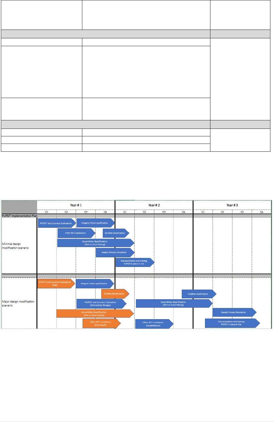
GMP ANNEX 1 DRAFT (VERSION 12)
IMPLEMENTATION TIMING EXAMPLE 8.82 and 8.88
25May2021 5 | P a g e
Facilities and Production area
modification
To allow PUPSIT operations to occur in the
production area, according to assembly design
(specific support, hard piping).e.g. provision of
electrical services
4. Qualification
Integrity Test equipment
Equipment Qualification
6 – 12 months
Standard
Qualification timeline
Assembly qualification
Steam sterilization/ Irradiation validation (Hard
piping, Single use system),
Cleaning validation evaluation, as required, if
product hard piping is changed.
For SUS implementation, additional validation
works to be considered (e.g. E&L,
biocompatibility…)
Aseptic Process Simulation
Additional manipulations downstream of the
sterilizing filter. Usually 3 consecutive runs will be
required
5. Document revision and approval
SOP
To integrate the PUPSIT operations
3 Months
Master Batch Record
To integrate the PUPSIT operations
Operator Training
To standardise PUPSIT operations
Typical implementation scenarios:
The scenario below reflects real-life situations where first intent strategies may result in failures during
development and require additional development /repeat testing.
Regulatory Impact:
The regulatory impact linked to the PUPSIT implementation is depending of the modification
required and is specific to the product submission file. The timeline example above does not include
the time required for regulatory approvals.
In some cases, e.g. if a filter change is required, a regulatory assessment could lead to the change
being identified as a major change. Depending on the variation type required and the number of
countries where approval is required the impact to the PUPSIT implementation timeline could be
minimal or extend the implementation time significantly.

GMP ANNEX 1 DRAFT (VERSION 12)
IMPLEMENTATION TIMING EXAMPLE 8.82 and 8.88
25May2021 6 | P a g e
Potential Challenges to Overcome:
• PUPSIT and Process Evaluation
- Impact on IT method design in case of filterability issue (e.g., Pressure and test duration,
Product non compatibility with the gas
If hydrophobic spot generation encountered due to the sterilization process or improve wetting
conditions, change the sterilization mode or change the filter.
- Impact on integrity test for product filtered at high temperature (Temperature stabilization
required)
• Facility design
- Shutdown availabilities (e.g., Clean Compressed Air (CCA)/Nitrogen (N2) installation, hard
piping modification,)
• BCT Validation
- Due to COVID 19 crisis, many critical pharmaceutical (filter, Single Use Systems, BCT validation,
...) suppliers are facing significant demand and there is a limitation in how quickly BCT on new
assemblies can be conducted.
- Revalidation needed in case of failures impacting process evaluation (e.g., failed with Bubble
point, then need to be redesigned with diffusion flow)
• Assemblies qualification
- Filter location in grade A (e.g., requirement 8.82), may need redesign in order to allow PUPSIT
activities to be conducted in a robust aseptic manner: supplier’s support needed, this may
impact on execution time
- Reevaluation of the use of redundant filtration
- Resolution of high-pressure constraints of SUS and the higher pressures needed for PUPSIT
for some filter media e.g. PES
Summary:
PUPSIT Implementation is very filter system design and product/process specific. For some final
filtration processes, PUPSIT implementation for an existing filtration process will require additional
development and optimization, including significant changes to the existing
process/facility/equipment.
Conclusion:
PUPSIT implementation could require a minimum of 1.5 year and up to or greater than 3 years
depending on the complexity of the configurations, where unexpected failures result occur from first
intent strategies and additional development is needed, and the time for global regulatory approval
which is dependent on the level of reporting required.
