
Read and observe all warnings on this unit
before operating it.
DO NOT operate this equipment unless all
factory-installed guards and shields are properly
secured in place.
WARNING
OPERATION & MAINTENANCE MANUAL
AX20 and BX20 Forklift Trucks
Federal Environmental Protection Agency (EPA) Emission-Control Compliant
S/N 670001A~ and 580001A~
REVISED: FEBRUARY 2007
AX20
BX20
OM073R
AX20 Gasoline & LPG FG15/18ST-17, FG15HC-17
FG15/18HT-17
BX20 Gasoline & LPG FG20/25/30/35S(H)(T/C)-14
FG20/25/30C-14, FG20/25T-14
FG20/25/30HT-14
BX20 Diesel FD20/25/30T-14
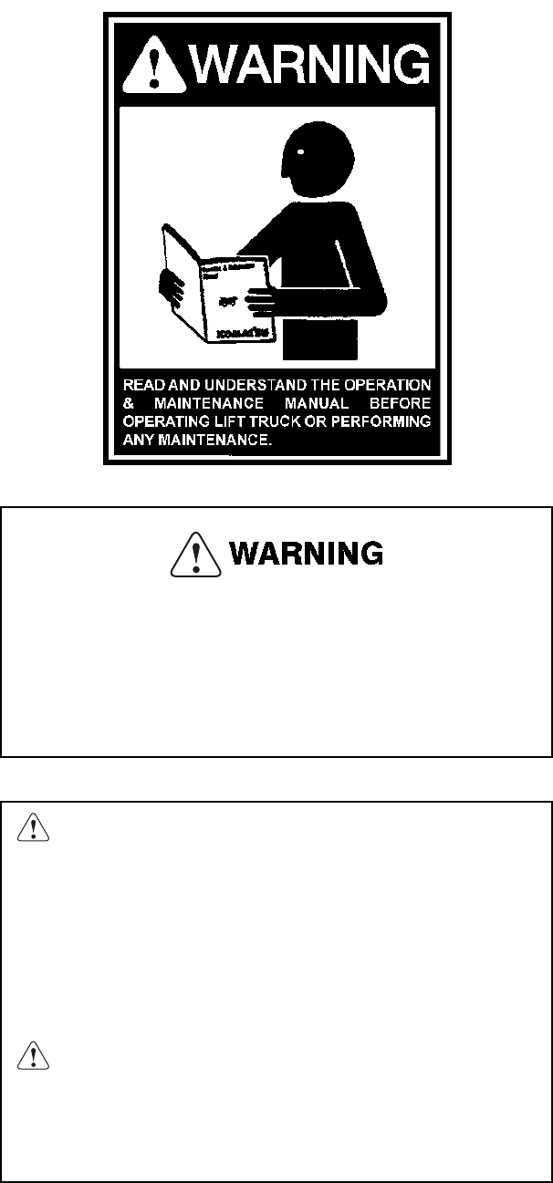
Unsafe use of this machine may cause serious injury or death.
Operators and maintenance personnel must read this manual, must
be trained and authorized by the employer, before operating or
maintaining this machine. This manual should be kept in or near the
machine for reference and periodically reviewed by all personnel
who come in contact with the machine.
WARNING: Breathing diesel engine exhaust exposes you to
chemicals known to the State of California to cause cancer and birth
defects or other reproductive harm.
• Always start and operate the engine in a well-ventilated area.
• If in an enclosed area, vent the exhaust to the outside.
• Do not modify or tamper with the exhaust system.
• Do not idle the engine except as necessary.
For more information go to www.P65warnings.ca.gov/diesel
WARNING: This product can expose you to chemicals including
lead, which is known to the State of California to cause cancer and
birth defects or other reproductive harm.
For more information go to www.P65warnings.ca.gov
The information and specifications contained herein were accurate at the time of
publication, but may change without notice as required for product improvements.
Neither Komatsu Forklift USA, LLC nor its parent company nor any of its subsidiaries will
be held responsible for damages due to misuse or inappropriate use of its products.
© Copyright 2011, Komatsu Forklift USA, LLC. All rights reserved. No part of this
document may be photocopied or reproduced in any way without prior written consent of
Komatsu Forklift USA, LLC.

CONTENTS
3
CONTENTS
FOREWORD
1. FOREWORD ................................................................................................................... 1-1
2. SAFETY INFORMATION ................................................................................................ 1-2
3. RUNNING IN A NEW LIFT TRUCK ................................................................................ 1-3
3.1 RUNNING IN A NEW LIFT TRUCK..............................................................................................1-3
3.2 FIRST MONTH OF SERVICE (OR INITIAL 200 HOURS OF SERVICE).....................................1-3
3.3 MODEL LINE UP ..........................................................................................................................1-4
4. WARRANTY AND SERVICE FOR NEW LIFT TRUCK .................................................. 1-5
4.1 GENUINE KOMATSU FORKLIFT PARTS ...................................................................................1-5
4.2 FEDERAL EPA EMISSION CONTROL STATEMENT
FOR OFF-ROAD LSI (NON-DIESEL) ENGINES (K21 AND K25 ENGINES) ...........................1-6
4.3 FEDERAL EPA EMISSION CONTROL STATEMENT FOR
OFF-ROAD DIESEL ENGINES (4D94E ENGINES) .................................................................1-9
5. LOCATION OF PLATES AND SERIAL NUMBER ....................................................... 1-12
5.1 UL (UNDERWRITERS LABORATORIES) PLATE .....................................................................1-12
5.2 EMBOSSED VEHICLE SERIAL NUMBER.................................................................................1-12
5.3 CAPACITY DATA PLATE WITH VEHICLE SERIAL NUMBER..................................................1-12
5.4 ENGINE SERIAL NUMBER........................................................................................................1-12
6. CONTACTING KOMATSU FORKLIFT......................................................................... 1-13
7. MODEL CODING SYSTEM........................................................................................... 1-14
8. EPA EMISSION CONTROL WARRANTY STATEMENT (GASOLINE/LPG) .............. 1-15
9. EPA EMISSION CONTROL WARRANTY STATEMENT (DIESEL)............................. 1-16
SAFETY
10. SAFETY MANAGEMENT ............................................................................................... 2-1
11. SAFE TRAVEL................................................................................................................ 2-6
12. LOADING OPERATIONS ............................................................................................. 2-14
13. STOPPING AND PARKING.......................................................................................... 2-20
14. INSPECTION AND MAINTENANCE ............................................................................ 2-21
15. STRUCTURE AND STABILITY OF THE LIFT TRUCK................................................ 2-28
16. SAFETY LABELS ......................................................................................................... 2-31
OPERATION
17. OVERVIEW OF LIFT TRUCK ......................................................................................... 3-1

CONTENTS
4
17.1 GENERAL VIEW OF LIFT TRUCK ..............................................................................................3-1
17.2 INSTRUMENTS AND CONTROLS ..............................................................................................3-2
17.3 METER PANEL COMPONENTS .................................................................................................3-3
18. EXPLANATION OF COMPONENTS .............................................................................. 3-4
18.1 EXPLANATION OF INSTRUMENTS AND CONTROLS..............................................................3-4
18.2 EXPLANATION OF METER PANEL COMPONENTS .................................................................3-9
19. REMOVAL AND INSTALLATION OF ATTACHMENTS .............................................. 3-13
19.1 SAFETY PRECAUTIONS...........................................................................................................3-13
19.2 FORKS .......................................................................................................................................3-13
19.3 CARRIAGE.................................................................................................................................3-14
19.4 MAST..........................................................................................................................................3-14
19.5 SIDE SHIFT, FORK POSITIONER AND CLAMP ATTACHMENTS...........................................3-15
20. OPERATOR’S COMPARTMENT ................................................................................. 3-16
20.1 ADJUSTING THE SEAT POSITION ..........................................................................................3-16
20.2 ADJUSTING THE RECLINING ANGLE .....................................................................................3-16
20.3 ADJUSTING THE SUSPENSION ..............................................................................................3-17
20.4 FITTING AND RELEASING THE SEAT BELT ...........................................................................3-17
21. ENGINE HOOD ............................................................................................................. 3-18
21.1 OPENING THE ENGINE HOOD ................................................................................................3-18
21.2 CLOSING THE ENGINE HOOD.................................................................................................3-19
21.3 FORK STOPPER .......................................................................................................................3-19
22. TRAVEL OPERATIONS ............................................................................................... 3-20
22.1 CHECK BEFORE OPERATION .................................................................................................3-20
22.2 MOUNTING/DISMOUNTING .....................................................................................................3-29
22.3 TRAVELING ...............................................................................................................................3-30
22.4 STARTING AND INCHING ON SLOPE .....................................................................................3-34
22.5 TURNING ...................................................................................................................................3-35
22.6 TEMPORARY STOPPING AND PARKING ...............................................................................3-36
22.7 FORK SPREAD ADJUSTMENT.................................................................................................3-37
22.8 LOAD HANDLING OPERATION ................................................................................................3-38
22.9 CHECK AFTER OPERATION ....................................................................................................3-42
23. COLD WEATHER OPERATION................................................................................... 3-43
23.1 PREPARATIONS FOR LOW TEMPERATURE .........................................................................3-43
23.2 PRECAUTIONS AFTER COMPLETING OPERATIONS ...........................................................3-44
24. HANDLING IN HEAVY-DUTY CONDITIONS ............................................................... 3-45
24.1 PRECAUTIONS WHEN USING IN HEAVY-DUTY CONDITIONS .............................................3-45
24.2 CLEAN INSIDE OF COOLING SYSTEM ...................................................................................3-45
24.3 CLEAN RADIATOR FINS ...........................................................................................................3-45
24.4 CHECK FAN BELT TENSION....................................................................................................3-45
24.5 ACTION WHEN ENGINE HAS OVERHEATED .........................................................................3-45
25. LONG-TERM STORAGE .............................................................................................. 3-46

CONTENTS
5
25.1 BEFORE STORAGE ..................................................................................................................3-46
25.2 DURING STORAGE ...................................................................................................................3-46
25.3 AFTER STORAGE .....................................................................................................................3-46
MAINTENANCE
26. OUTLINE OF SERVICE .................................................................................................. 4-1
26.1 OIL................................................................................................................................................4-1
26.2 GREASE.......................................................................................................................................4-1
26.3 OIL STORAGE AND PRESERVATION........................................................................................4-1
26.4 FILTERS .......................................................................................................................................4-1
27. LUBRICANT LIST ........................................................................................................... 4-2
27.1 AX – GASOLINE/LPG ENGINE ...................................................................................................4-2
27.2 BX – GASOLINE/LPG ENGINE ...................................................................................................4-3
27.3 BX – DIESEL ENGINE .................................................................................................................4-4
27.4 OIL AND GREASING CHART ......................................................................................................4-5
28. SERVICE DATA .............................................................................................................. 4-6
28.1 AX SERVICE DATA – ALL MODELS ...........................................................................................4-6
28.2 BX SERVICE DATA – GASOLINE/LPG ENGINE ........................................................................4-7
28.3 BX SERVICE DATA – DIESEL ENGINE ......................................................................................4-8
28.4 TORQUE LIST..............................................................................................................................4-9
29. PERIODIC REPLACEMENT OF SAFETY CRITICAL PARTS..................................... 4-10
30. MAINTENANCE SCHEDULE CHART.......................................................................... 4-11
31. MAINTENANCE ............................................................................................................ 4-15
31.1 FIRST ONE MONTH OR INITIAL 200 HOURS SERVICE .........................................................4-15
31.2 EVERY 2 WEEKS OR EVERY 100 HOURS SERVICE .............................................................4-19
31.3 EVERY MONTH OR EVERY 200 HOURS SERVICE ................................................................4-19
31.4 EVERY 500 HOURS SERVICE..................................................................................................4-26
31.5 EVERY 3 MONTHS OR EVERY 600 HOURS SERVICE...........................................................4-27
31.6 EVERY 1,000 HOURS SERVICE (EPA AND DIESEL ENGINES).............................................4-27
31.7 EVERY 6 MONTHS OR EVERY 1,200 HOURS SERVICE........................................................4-27
31.8 EVERY 2,000 HOURS SERVICE...............................................................................................4-28
31.9 EVERY YEAR OR EVERY 2,400 HOURS SERVICE ................................................................4-28
31.10 EVERY 18 MONTHS OR EVERY 3,600 HOURS SERVICE......................................................4-29
32. REPLACEMENT PROCEDURES ................................................................................. 4-30
32.1 REPLACING FUSES AND RELAYS ..........................................................................................4-30
32.2 REPLACING TIRES ...................................................................................................................4-32
32.3 REPLACING LAMPS..................................................................................................................4-33
33. LIFT TRUCK WASHING PROCEDURE ....................................................................... 4-34
33.1 GENERAL PRECAUTIONS........................................................................................................4-34
33.2 WASHING INSTRUCTIONS.......................................................................................................4-34

CONTENTS
6
TECHNICAL DATA
34. TECHNICAL DATA - AX/BX MODEL LIFT TRUCKS .................................................... 5-1
34.1 AX (GASOLINE/LPG ENGINES)..................................................................................................5-1
34.2 BX (DIESEL ENGINES) ...............................................................................................................5-3
34.3 BX (GASOLINE/LPG ENGINES)..................................................................................................5-4

READ AND FOLLOW ALL SAFETY PRECAUTIONS.
FAILURE TO DO SO MAY RESULT IN SERIOUS
INJURY OR DEATH.
FOREWORD

1. FOREWORD
1-1
1. FOREWORD
This manual provides rules and guidelines which will help you use this lift truck safely and effectively.
Always be sure to read and understand this manual thoroughly before operating and performing maintenance.
Some actions involved in operation and maintenance of the lift truck can cause a serious accident if they are not
done in the manner described in this manual.
• Improper operation and maintenance of this lift truck can be hazardous and could result in
serious injury or death.
• Operators and maintenance personnel should read this manual thoroughly before beginning
operation or maintenance.
• Keep this manual handy and have all personnel read it periodically.
• Do not use this lift truck unless you are sure that you understand the contents completely.
• If this manual has been lost, or has become dirty or worn and cannot be read, request a
replacement manual from your Komatsu Forklift dealer.
• Komatsu Forklift delivers lift trucks that comply with (to the best of our knowledge at the time
of delivery) all applicable regulations and standards of the country to which they have been
shipped. If this lift truck has been purchased in another country or purchased from someone
in another country, it may lack certain safety devices and specifications that are necessary for
use in your country. If there is any question about whether your product complies with the
applicable standards and regulations of your country, consult your Komatsu Forklift dealer
before operating the lift truck.
• Continuing improvements in the design of this lift truck may not be reflected in this manual.
Consult Komatsu Forklift or your Komatsu Forklift dealer for the latest available information
on your lift truck or for questions regarding information in this manual.
• Information on safety is given in the SAFETY, OPERATION and MAINTENANCE sections
throughout this manual; please read it carefully and completely.

2. SAFETY INFORMATION
1-2
2. SAFETY INFORMATION
This OPERATING MANUAL contains information necessary for the operation of a basic fork lift truck. Optional
equipment is sometimes installed that can change some operating characteristics described in this manual. Make
sure the necessary instructions are available and understood before operating the lift truck.
Some of the components and systems described in this OPERATING MANUAL will NOT be installed on your unit.
If you have a question about any item described, contact your local dealer.
Additional information that describes the safe operation and use of lift trucks is available from the following
sources:
• Employment safety and health standards or regulations
• Safety codes and standards, such as: American National Standard, ANSI B56.1, Safety Standard For Low Lift
and High Lift Trucks.
• Publications from government safety agencies, government insurers, private insurers and private organiza-
tions, such as: Accident Prevention Manual for Industrial Operations from the National Safety Council.
NOTE: Forklift trucks are not intended for use on public roads.
Most accidents are caused by a failure to follow fundamental safety rules for the operation and maintenance of lift
trucks. To avoid accidents, read, understand and follow all precautions and warnings in this manual and on the lift
truck before operating and performing maintenance. Do not operate or carry out maintenance of this lift truck
unless you are sure that you understand the explanations and procedures completely.
To identify safety messages in this manual and on lift truck labels, the following signal words are used.
These safety messages or labels describe precautions that must be taken to
avoid a hazard which carries a serious risk of serious injury or death.
These safety messages or labels usually describe precautions that must be taken
to avoid a hazard which may lead to serious injury or death.
This word is used on safety messages and safety labels for hazards which could
result in injury or damage to the lift truck or surrounding property if the hazard is
not avoided.
Safety precautions are described in the SAFETY, OPERATION and MAINTENANCE sections of this manual.
Komatsu Forklift cannot predict every circumstance that might involve a potential hazard in operation and
maintenance. Therefore, the safety messages in this manual and on the lift truck may not include all possible
safety precautions.
If any procedures or actions not specifically recommended or allowed in this manual are used, it is your
responsibility to be sure that you and others can do such procedures and actions safely and without damaging the
lift truck. If you are unsure about the safety of some procedures, contact your Komatsu Forklift dealer.
The procedures and precautions given in this manual apply only to intended uses of the lift truck. If you use your lift
truck for any unintended use that is not specifically prohibited, you must be sure that it is safe for you and others. In
no event should you or others engage in prohibited uses or actions as described in this manual.
This word is used for precautions that may not lead to damage or failure, but which must be taken
to avoid actions that could shorten the life of the lift truck.
NOTICE

3. RUNNING IN A NEW LIFT TRUCK
1-3
3. RUNNING IN A NEW LIFT TRUCK
3.1 RUNNING IN A NEW LIFT TRUCK
Your Komatsu lift truck has been thoroughly adjusted and tested before shipment.
However, operating the lift truck under severe conditions at the beginning can adversely affect performance and
shorten the lift truck life. Be sure to take special care concerning the following items during this initial period of
operation.
• Avoid operation with heavy loads or at high speeds.
• Avoid sudden starting or acceleration, unnecessarily abrupt braking and sharp turning, except in the case of
emergency.
3.2 FIRST MONTH OF SERVICE (OR INITIAL 200 HOURS OF SERVICE)
For new lift truck, carry out the following maintenance only after the first month or 200 hours.
Unit Check Items Remarks
Engine
Change oil in engine oil pan Page 4-16
Replace oil filter cartridge Page 4-16
Check & adjust engine valve clear-
ance
Tighten (retorque) engine cylinder
head bolts
Check spark plugs for burning of
electrode, burning of insulator
Page 4-19
Check & clean air cleaner element Page 4-22
Check ignition timing
Check & adjust alternator belt (drive
belt) tension
Page 3-23
TORQFLOW
transmission
Change transmission fluid
Page 4-18
Clean strainer
Differential Change oil Page 4-18
Hydraulic tank
Change oil
Page 4-15
Replace line filter
Clean strainer
Clean inside tank
Misc. bolts & nuts Tighten
Particularly lug (hub) nuts, overhead guard
mounting bolts, backrest mounting bolts,
and operator's seat mounting bolts
Other See “Check Before Operation” Page 3-20

3. RUNNING IN A NEW LIFT TRUCK
1-4
3.3 MODEL LINE UP
APPLICABLE “EPA” LIFT TRUCK MODELS
Model Description
AX (K21 Gasoline Engine)
FG15ST-17 3,000 lb. capacity, Cushion Tire, TORQFLOW
FG15STLS-17 3,000 lb. capacity, Cushion Tire, TORQFLOW, Liquid Propane Special
FG18ST-17 3,500 lb. capacity, Cushion Tire, TORQFLOW
FG18STLS-17 3,500 lb. capacity, Cushion Tire, TORQFLOW, Liquid Propane Special
FG15HC-17 3,000 lb. capacity, Pneumatic Tire, High Performance, Clutch
FG15HT-17 3,000 lb. capacity, Pneumatic Tire, High Performance, TORQFLOW
FG15HTLS-17 3,000 lb. capacity, Pneumatic Tire, High Performance, TORQFLOW, Liquid Propane Special
FG18HT-17 3,500 lb. capacity, Pneumatic Tire, High Performance, TORQFLOW
FG18HTLS-17 3,500 lb. capacity, Pneumatic Tire, High Performance, TORQFLOW, Liquid Propane Special
BX (K21 and K25 Gasoline Engines)
FG20ST-14 4,000 lb. capacity, Cushion Tire, TORQFLOW
FG20STUS-14 4,000 lb. capacity, Cushion Tire, TORQFLOW, Gasoline Special
FG20STLS-14 4,000 lb. capacity, Cushion Tire, TORQFLOW, Liquid Propane Special
FG20SHT-14 4,000 lb. capacity, Cushion Tire, High Performance, TORQFLOW
FG25ST-14 5,000 lb. capacity, Cushion Tire, TORQFLOW,
FG25STUS-14 5,000 lb. capacity, Cushion Tire, TORQFLOW, Gasoline Special
FG25STLS-14 5,000 lb. capacity, Cushion Tire, TORQFLOW, Liquid Propane Special
FG25SHT-14 5,000 lb. capacity, Cushion Tire, High Performance, TORQFLOW
FG25SHTLS-14 5,000 lb. capacity, Cushion Tire, TORQFLOW, Liquid Propane Special
FG30SHT-14 6,000 lb. capacity, Cushion Tire, High Performance, TORQFLOW
FG30SHTLS-14 6,000 lb. capacity, Cushion Tire, High Performance, TORQFLOW, Liquid Propane Special
FG20C-14 4,000 lb. capacity, Pneumatic Tire, Clutch
FG20T-14 4,000 lb. capacity, Pneumatic Tire, TORQFLOW
FG20TUS-14 4,000 lb. capacity, Pneumatic Tire, TORQFLOW, Gasoline Special
FG20TLS-14 4,000 lb. capacity, Pneumatic Tire, TORQFLOW, Liquid Propane Special
FG20HT-14 4,000 lb. capacity, Pneumatic Tire, High Performance, TORQFLOW
FG20HTLS-14 4,000 lb. capacity, Pneumatic Tire, High Performance, TORQFLOW, Liquid Propane Special
FG25C-14 5,000 lb. capacity, Pneumatic Tire, Clutch
FG25T-14 5,000 lb. capacity, Pneumatic Tire, TORQFLOW
FG25TUS-14 5,000 lb. capacity, Pneumatic Tire, TORQFLOW, Gasoline Special
FG25TLS-14 5,000 lb. capacity, Pneumatic Tire, TORQFLOW, Liquid Propane Special
FG25HT-14 5,000 lb. capacity, Pneumatic Tire, High Performance, TORQFLOW
FG25HTLS-14 5,000 lb. capacity, Pneumatic Tire, High Performance, TORQFLOW, Liquid Propane Special
FG30C-14 6,000 lb. capacity, Pneumatic Tire, Clutch
FG30HT-14 6,000 lb. capacity, Pneumatic Tire, High Performance, TORQFLOW
FG30HTUS-14 6,000 lb. capacity, Pneumatic Tire, High Performance, TORQFLOW, Gasoline Special
FG30HTLS-14 6,000 lb. capacity, Pneumatic Tire, High Performance, TORQFLOW, Liquid Propane Special
BX (4D94E Diesel Engine)
FD20T-14 4,000 lb. capacity, Pneumatic Tire, TORQFLOW
FD20TUS-14 4,000 lb. capacity, Pneumatic Tire, TORQFLOW, Diesel Special
FD25T-14 5,000 lb. capacity, Pneumatic Tire, TORQFLOW
FD25TUS-14 5,000 lb. capacity, Pneumatic Tire, TORQFLOW, Diesel Special
FD30T-14 6,000 lb. capacity, Pneumatic Tire, TORQFLOW
FD30TUS-14 6,000 lb. capacity, Pneumatic Tire, TORQFLOW, Diesel Special

4. WARRANTY AND SERVICE FOR NEW LIFT TRUCK
1-5
4. WARRANTY AND SERVICE FOR NEW LIFT TRUCK
4.1 GENUINE KOMATSU FORKLIFT PARTS
Komatsu Forklift genuine parts are manufactured from the same
materials, and by the same methods, as the parts built in the new
lift truck.
In the event that the customer uses imitation parts, Komatsu Forklift
will not be held accountable for any faults which result from the use
of such imitation parts, and Komatsu Forklift warranty will not be
applicable.
Always use genuine Komatsu Forklift parts when replacing parts.

4. WARRANTY AND SERVICE FOR NEW LIFT TRUCK
1-6
4.2 FEDERAL EPA EMISSION CONTROL STATEMENT
FOR OFF-ROAD LSI (NON-DIESEL) ENGINES (K21 AND K25
ENGINES)
This section presents information concerning the correct labeling, warranty, parts and maintenance of K21 and K25
engines in order to comply with the EPA off-road, large-spark-ignition (LSI) engine regulations.
4.2.1 LABELS REQUIRED AND LABEL LOCATIONS
All “K” series engines will display the required identification label as follows.
Location on K21/K25 Series engines:
Emission compliance label (SAMPLE shown below)

4. WARRANTY AND SERVICE FOR NEW LIFT TRUCK
1-7
4.2.2 WARRANTY
The following statement is hereby provided as required by regulations of the United States Environmental
Protection Agency (EPA).
YOUR WARRANTY RIGHTS AND OBLIGATIONS
All off-road large spark-ignition (LSI) engines must be designed, built and equipped to meet the Federal EPA’s
stringent anti-smog standards.
Komatsu Forklift USA, LLC (“KFI”) must warrant the emission control system on your engine for the periods of time
listed below provided there has been no abuse, damage, neglect or improper maintenance of your engine.
Your emission control system may include parts such as the carburetor, regulator or fuel-injection system, ignition
system, engine computer unit (ECM), catalytic converter and air induction system.
Also included may be sensors, hoses, belts, connectors and other emission-related assemblies.
Where a warrantable condition exists, an Authorized Komatsu Forklift Dealer will repair your LSI engine at no cost
to you, including diagnosis, parts and labor.
MANUFACTURER’S WARRANTY COVERAGE
Beginning January 1, 2004 off-road large spark-ignition EPA engines are warranted for the time periods listed
below. If any emission-related part on your engine is defective, the part will be repaired or replaced by an
Authorized Komatsu Forklift Dealer.
OWNER’S WARRANTY RESPONSIBILITIES
As the off-road LSI engine owner, you are responsible for the performance of the required maintenance listed in
your Operation and Maintenance Manual.
KFI recommends that you retain receipts covering maintenance on your off-road engine, but KFI cannot deny
warranty solely for the lack of receipts or for your failure to ensure the performance of all scheduled maintenance.
As the off-road large spark-ignition engine owner, you should be aware, however, that KFI may deny you warranty
coverage if your off-road large spark-ignition engine, or a part thereof, has failed due to abuse, damage, neglect,
improper maintenance or unapproved modifications.
Your engine is designed to operate on gasoline and/or LPG fuel. Use of any other fuel may result in your engine no
longer operating in compliance with the Federal EPA’s emissions requirements.
You are responsible for initiating the warranty process. It is suggested that you present your off-road large spark-
ignition engine to an Authorized Komatsu Forklift Dealer as soon as you become aware that a problem exists. The
warranty repairs should be completed by the dealer as expeditiously as possible.
If you have any questions regarding your warranty rights and responsibilities, you should contact the Komatsu
Forklift Product Support Dept. at (847) 437-5800.
In addition to the standard warranty periods, the components listed below are covered by the following specific
warranty periods.
EMISSION CONTROL WARRANTY – 36 MONTHS OR 2,500 HOURS FOR GENERAL PARTS
For the first 2,500 operating hours, or for a period of thirty-six months from the date of the first use by the original
purchaser from an Authorized Komatsu Forklift Dealer, whichever occurs first, KFI warrants the following emission-
related parts:
• Oxygen sensor • PCV valve
• W
a
ter temperature sensor • Gasoline injector
• LPG injector • LPG pressure sensor
• LPG solenoid • LPG switching module
• Mass air flow sensor • Throttle chamber
• Ignition coil • Crankshaft position sensor
• Camshaft position sensor • Distributor
• Spark plugs

4. WARRANTY AND SERVICE FOR NEW LIFT TRUCK
1-8
EMISSION CONTROL WARRANTY – 36 MONTHS OR 4,000 HOURS FOR POWER TRAIN PARTS
• Intake manifold
• Exhaust manifold
EMISSION CONTROL WARRANTY – 60 MONTHS OR 3,500 HOURS FOR GENERAL PARTS
• ECM
• Catalytic converter
• Vaporizer
NOTICE
Follow the instructions in the Operations Manual concerning any other maintenance programs not
required for EPA compliance.
For questions and additional information concerning EPA Diesel Engine Exhaust Regulations, contact:
Komatsu Forklift U.S.A., LLC
c/o Komatsu American Corp.
One Continental Towers
1701 W. Golf Rd.
Rolling Meadows, IL 60008
(847) 437-5800

4. WARRANTY AND SERVICE FOR NEW LIFT TRUCK
1-9
4.3 FEDERAL EPA EMISSION CONTROL STATEMENT FOR
OFF-ROAD DIESEL ENGINES (4D94E ENGINES)
Exhaust emissions produced by diesel engines are regulated by the United States Environmental Protection
Agency (EPA). This section presents information concerning the correct labeling, warranty, parts and maintenance
of 4D94E diesel engines in order to comply with current EPA regulations.
4.3.1 LABELS REQUIRED AND LABEL LOCATIONS
All certified 4D94E diesel engines will display the required identification label as follows:
• 4D94E diesel engines: Labels will be affixed to all appropriate engines on KFI production trucks.
Location on 4D94E Series diesel engines:

4. WARRANTY AND SERVICE FOR NEW LIFT TRUCK
1-10
4.3.2 WARRANTY
The following statement is hereby provided as required by regulations of the United States Environmental
Protection Agency (EPA).
YOUR WARRANTY RIGHTS AND OBLIGATIONS
The Federal EPA and KFI are pleased to explain the emission control system warranty on your 2004 or later Diesel
heavy duty off-road engine. All new, heavy-duty off-road engines must be designed, built and equipped to meet the
EPA’s stringent anti-smog standards. KFI must warrant the emission control system on your engine for the period
of time listed below, provided there has been no abuse, damage, neglect or improper maintenance of your engine.
Your emission control system may include parts such as fuel injection pump. Also included may be hoses, belts,
connectors and other emission-related assemblies.
Where a warrantable condition exists, an authorized Komatsu Forklift dealer will repair the heavy-duty off-road
engine at no cost to the owner, including diagnosis, parts and labor.
Now, KFI hereby certifies that diesel engines for lift trucks produced in 2004 model year and after shall be
regulated by Federal EPA exhaust gaseous regulations. The difference between current and EPA-certified engines
is only the label attached on the engine. See available drawing and/or illustration of emission label and its location.
MANUFACTURER’S WARRANTY COVERAGE
Beginning January 1, 2004 heavy-duty off-road EPA engines are warranted for a period of five (5) years, or three-
thousand (3,000) hours of operation, whichever occurs first. If any emission-related part on your engine is
defective, the part will be repaired or replaced by at an authorized Komatsu Forklift dealer.
EMISSION-RELATED PARTS
• Fuel injection pump
• Fuel injection nozzles
• Turbocharger
OWNER’S WARRANTY RESPONSIBILITIES
As the heavy-duty off-road engine owner, you are responsible for the performance of the required maintenance
listed in owner's manual (Instruction Manual). KFI recommends that you retain all receipts and records covering the
maintenance on your engine, but KFI cannot deny warranty solely for the lack of receipts and records or for your
failure to ensure the performance of all scheduled maintenance. For your reference, the following is an emission
control maintenance schedule for certified Diesel engines.
Keep records to show proof of compliance with the required maintenance practices and intervals.
• As the heavy-duty off-road engine owner you should, however, be aware that KFI may deny your warranty cov-
erage if your heavy-duty off-road engine or part has failed due to abuse, damage, neglect, improper mainte-
nance or disapproved modifications.
• Your engine is designed to operate on commercial diesel fuel only. Use of any other fuel in our engine will
result in the engine operating in non-compliance with the Federal EPA regulations.
You are responsible for initiating the warranty process. It is suggested that you present your heavy duty off-
road engine to an authorized Komatsu Forklift dealer as soon as you become aware that problem exists. The
warranty repair should be completed by the dealer as expeditiously as possible.
• If you have any questions regarding your warranty rights and responsibilities, you should contact the autho-
rized Komatsu Forklift dealer.
•
Check oil level and coolant level Every day
• Change of
lubricating oil Every 200 hours
• Change lubricating oil
filter Every 600 hours
• Initial adjustment of valve clearance Every 200 hours
• Change fuel filter Every 500 hours
• Check turbocharger, rebuild or replace if necessary Every 2,000 hours
• Adjust valve clearance Every 2,000 hours
• Check fuel injection nozzles, replace if necessary Every 2,000 hours

4. WARRANTY AND SERVICE FOR NEW LIFT TRUCK
1-11
LIMITATIONS
KFI is not responsible for resultant damages to an emission-related part or component resulting from:
• Any application or installation KFI deems improper as explained in the Instruction Manual.
• Attachments, accessory items or parts not authorized for use by KFI.
• Improper off-road engine maintenance, repair or abuse.
• Owner's unreasonable delay in making the product available after being notified of a potential product problem.
This warranty is in addition to the KFI standard warranty applicable to the off-road engine product involved.
Remedies under this warranty are limited to the provision of material and services as specified herein. KFI is not
responsible for incidental or consequential damages, such as downtime or lost use of the forklift truck.
CUSTOMER ASSISTANCE – EMISSION CONTROL SYSTEMS WARRANTY
KFI aims to ensure that the Emission Control Systems Warranty is properly administered. In the event that you do
not receive the warranty service to which you believe you are entitled under the Emission Control Systems
Warranty, call or write to your Komatsu Forklift Dealer.
Authorized dealers are recommended for major maintenance and repair work, as they are staffed with trained
personnel, proper tools and are aware of the latest maintenance methods and procedures. Owners and others who
desire to perform their own work should purchase a service manual and obtain current service information from
their KFI engine dealer.
NOTICE
Follow the instructions in the Operations Manual concerning any other maintenance programs not
required for EPA compliance.
For questions and additional information concerning EPA Diesel Engine Exhaust Regulations, contact:
Komatsu Forklift U.S.A., LLC
c/o Komatsu American Corp.
One Continental Towers
1701 W. Golf Rd.
Rolling Meadows, IL 60008
(847) 437-5800

5. LOCATION OF PLATES AND SERIAL NUMBER
1-12
5. LOCATION OF PLATES AND SERIAL NUMBER
5.1 UL (Underwriters Laboratories) Plate
Located on the outside front left of the dashboard.
5.2 Embossed Vehicle Serial Number
Stamped on top of the left front fender.
5.3 Capacity Data Plate With Vehicle Serial Number
Located on the bonnet (hood) to the right of the operator’s
seat.
5.4 Engine Serial Number
Gas/LPG engine: stamped on left side of engine.
Diesel engine: stamped on right side of engine.
Gasoline/LPG engine Diesel engine

6. CONTACTING KOMATSU FORKLIFT
1-13
6. CONTACTING KOMATSU FORKLIFT
CONTACTING KOMATSU FORKLIFT
When contacting a Komatsu Forklift dealer for parts ordering or problem consultation, always provide the lift
truck serial number embossed on the lift truck.
NOTICE
Take care not to damage or remove the embossed serial number.
Remark
The serial number can also be found on the capacity data plate.

7. MODEL CODING SYSTEM
1-14
7. MODEL CODING SYSTEM
Komatsu Forklift Model Coding System for
Internal Combustion Engine Trucks
Class IV (Cushion Tire) and V (Pneumatic Tire)
You can determine the lift truck
model from the model code on
the nameplate, which is located
on the top of the lift truck hood to
the right of the operator’s seat.
The key below describes the
code nomenclature.
In the example above, the FG30HTUS lift truck has a load capacity of
6,000 lbs., pneumatic tires, a high-performance gasoline engine,
TORQFLOW transmission, and anti-spark safety features.
Model: FG 30 HT US
Position: 1 2 3 4
Model Key
12 3 4
Vehicle & Fuel Type
Load Capacity
(Model = lbs)
Designations UL Safety Type
FG = Gasoline forklift
(includes LP)
FD = Diesel forklift
(BX only)
15 = 3,000
18 = 3,500
20 = 4,000
25 = 5,000
30 = 6,000
S = Cushion Tire
(no “S” = Pneumatic Tire)
H = High Performance
C = Clutch-type manual transmission
with dry, single-disc clutch
T = TORQFLOW-type power-shift
transmission with torque converter
US = Anti-Spark Gas or
Diesel Special,
depending on Fuel Type
LS = Anti-Spark Liquid
Propane Special

8. EPA EMISSION CONTROL WARRANTY STATEMENT (GASOLINE/LPG)
1-15
8. EPA EMISSION CONTROL WARRANTY STATEMENT (GASOLINE/LPG)
The following statement is provided as required by
regulations of the United States Environmental Protec-
tion Agency (EPA).
YOUR WARRANTY RIGHTS
AND OBLIGATIONS
All off-road large spark-ignition (LSI) engines must be
designed, built and equipped to meet the Federal
EPA’s stringent anti-smog standards.
Komatsu Forklift USA, Inc. ("KFI") must warrant the
emission control system on your engine for the periods
of time listed below provided there has been no abuse,
damage, neglect or improper maintenance of your
engine.
Your emission control system may include parts such
as the carburetor, regulator or fuel-injection system,
ignition system, engine computer unit (ECM), catalytic
converter and air induction system.
Also included may be sensors, hoses, belts, connec-
tors and other emission-related assemblies.
Where a warrantable condition exists, an Authorized
Komatsu Forklift Dealer will repair your LSI engine at
no cost to you, including diagnosis, parts and labor.
MANUFACTURER’S WARRANTY
COVERAGE
Beginning January 1, 2004 off-road large spark-igni-
tion EPA engines are warranted for the time periods
listed below. If any emission-related part on your
engine is defective, the part will be repaired or
replaced by an Authorized Komatsu Forklift Dealer.
OWNER’S WARRANTY
RESPONSIBILITIES
As the off-road LSI engine owner, you are responsible
for the performance of the required maintenance listed
in your Operation and Maintenance Manual.
KFI recommends that you retain receipts covering
maintenance on your off-road engine, but KFI cannot
deny warranty solely for the lack of receipts or for your
failure to ensure the performance of all scheduled
maintenance.
As the off-road large spark-ignition engine owner, you
should be aware, however, that KFI may deny you
warranty coverage if your off-road large spark-ignition
engine, or a part thereof, has failed due to abuse,
damage, neglect, improper maintenance or unap-
proved modifications.
Your engine is designed to operate on gasoline and/or
LPG fuel. Use of any other fuel may result in your
engine no longer operating in compliance with the
Federal EPA’s emissions requirements.
You are responsible for initiating the warranty process.
It is suggested that you present your off-road large
spark-ignition engine to an Authorized Komatsu
Dealer as soon as you become aware that a problem
exists. The warranty repairs should be completed by
the dealer as expeditiously as possible.
If you have any questions regarding your warranty
rights and responsibilities, you should contact
Komatsu's Product Support Dept. at 1-770-385-4815.
In addition to the standard warranty periods, the com-
ponents listed below are covered by the following spe-
cific warranty periods.
EMISSION CONTROL WARRANTY –
36 MONTHS OR 2,500 HOURS
FOR GENERAL PARTS
For the first 2,500 operating hours, or for a period of
thirty-six months from the date of the first use by the
original purchaser from an Authorized Komatsu Forklift
Dealer, whichever occurs first, KFI warrants the
following emission-related parts:
• Oxygen sensor
•PCV valve
• Water temperature sensor
• Gasoline injector
• LPG injector
• LPG pressure sensor
• LPG solenoid
• LPG switching module
• Mass air flow sensor
• Throttle chamber
• Ignition coil
• Crankshaft position sensor
• Camshaft position sensor
• Distributor
• Spark plugs
EMISSION CONTROL WARRANTY –
36 MONTHS OR 4,000 HOURS
FOR POWER TRAIN PARTS
• Intake manifold
• Exhaust manifold
EMISSION CONTROL WARRANTY –
60 MONTHS OR 3,500 HOURS
FOR GENERAL PARTS
•ECM
• Catalytic converter
• Vaporizer
Class IV & V ICE – U.S.A.
Komatsu Forklift U.S.A., Inc.
EPAGAS rev 02/04
FEDERAL ENVIRONMENTAL PROTECTION AGENCY (EPA) EMISSION CONTROL
WARRANTY STATEMENT (GASOLINE/LPG ENGINES)

9. EPA EMISSION CONTROL WARRANTY STATEMENT (DIESEL)
1-16
9. EPA EMISSION CONTROL WARRANTY STATEMENT (DIESEL)
The following statement is provided as required by regulations
of the United States Environmental Protection Agency (EPA).
YOUR WARRANTY RIGHTS
AND OBLIGATIONS
The Federal EPA and Komatsu Forklift USA, Inc. (hereinafter
referred to as "KFI") are pleased to explain the emission con-
trol system warranty on your 2004 or later Diesel heavy duty
off-road engine. All new, heavy-duty off-road engines must be
designed, built and equipped to meet the EPA’s stringent anti-
smog standards. KFI must warrant the emission control sys-
tem on your engine for the period of time listed below, pro-
vided there has been no abuse, damage, neglect or improper
maintenance of your engine.
Your emission control system may include parts such as fuel
injection pump. Also included may be hoses, belts, connectors
and other emission-related assemblies.
Where a warrantable condition exists, an authorized Komatsu
dealer will repair the heavy-duty off-road engine at no cost to
the owner, including diagnosis, parts and labor.
Now, KFI hereby certifies that diesel engines for lift trucks pro-
duced in 2004 model year and after shall be regulated by Fed-
eral EPA exhaust gaseous regulations. The difference
between current and EPA-certified engines is only the label
attached on the engine. See available drawing and/or illustra-
tion of emission label and its location.
MANUFACTURER’S WARRANTY
COVERAGE
Beginning January 1, 2004 heavy-duty off-road EPA engines
are warranted for a period of five (5) years, or three-thousand
(3,000) hours of operation, whichever occurs first. If any emis-
sion-related part on your engine is defective, the part will be
repaired or replaced by at an authorized Komatsu Forklift
dealer.
EMISSION RELATED PARTS
• Fuel Injection Pump
• Fuel Injection Nozzles
• Turbocharger
OWNER’S WARRANTY
RESPONSIBILITIES
As the heavy-duty off-road engine owner, you are responsible
for the performance of the required maintenance listed in
owner's manual (Instruction Manual). KFI recommends that
you retain all receipts and records covering the maintenance
on your engine, but KFI cannot deny warranty solely for the
lack of receipts and records or for your failure to ensure the
performance of all scheduled maintenance. For your refer-
ence, the following is an emission control maintenance sched-
ule for certified Diesel engines.
• Check oil level and coolant level – Everyday
• Change of lubricating – Every 200 hours
• Change lubricating oil filter – Every 200 hours
• Initial adjustment of valve clearance – Every 200 hours
• Change fuel filter – Every 500 hours
• Check turbocharger, rebuild or replace if necessary –
Every 2,000 hours
• Adjust valve clearance – Every 2,000 hours
• Check fuel injection nozzles, replace if necessary –
Every 2,000 hours
Keep records to show proof of compliance with the required
maintenance practices and intervals.
• As the heavy-duty off-road engine owner you should,
however, be aware that KFI may deny your warranty
coverage if your heavy-duty off-road engine or part has
failed due to abuse, damage, neglect, improper mainte-
nance or disapproved modifications.
• Your engine is designed to operate on commercial diesel
fuel only. Use of any other fuel in our engine will result in
the engine operating in non-compliance with the Federal
EPA regulations.
• You are responsible for initiating the warranty process. It
is suggested that you present your heavy duty off-road
engine to an authorized Komatsu dealer as soon as you
become aware that problem exists. The warranty repair
should be completed by the dealer as expeditiously as
possible.
If you have any questions regarding your warranty rights and
responsibilities, you should contact the authorized KFI dealer.
LIMITATIONS
KFI is not responsible for resultant damages to an emission-
related part or component resulting from:
• Any application or installation KFI deems improper as
explained in the Instruction Manual.
• Attachments, accessory items or parts not authorized for
use by KFI.
• Improper off-road engine maintenance, repair or abuse.
• Owner's unreasonable delay in making the product
available after being notified of a potential product prob-
lem.
This warranty is in addition to the KFI standard warranty appli-
cable to the off-road engine product involved.
Remedies under this warranty are limited to the provision of
material and services as specified herein. KFI is not responsi-
ble for incidental or consequential damages, such as down-
time or lost use of the forklift truck.
CUSTOMER ASSISTANCE –
EMISSION CONTROL SYSTEMS
WARRANTY
Komatsu Forklift aims to ensure that the Emission Control
Systems Warranty is properly administered. In the event that
you do not receive the warranty service to which you believe
you are entitled under the Emission Control Systems War-
ranty, call or write to your Komatsu Forklift Dealer.
Authorized dealers are recommended for major maintenance
and repair work, as they are staffed with trained personnel,
proper tools and are aware of the latest maintenance methods
and procedures. Owners and others who desire to perform
their own work should purchase a service manual and obtain
current service information from their KFI engine dealer.
Follow the instructions in the Operations Manual concerning
any other maintenance programs not required for EPA compli-
ance.
For questions and additional information concerning EPA Die-
sel Engine Exhaust Regulations, contact:
Komatsu Forklift U.S.A., Inc.
14481 Lochridge Blvd., Building 2
Covington, Georgia 30014
Voice phone: (770) 385-4815
Fax phone: (770) 385-4838
Class IV & V – U.S.A.
Komatsu Forklift U.S.A., Inc.
EPADSL rev 02/04
FEDERAL ENVIRONMENTAL PROTECTION AGENCY (EPA) EMISSION CONTROL
WARRANTY STATEMENT (DIESEL ENGINES)

READ AND FOLLOW ALL SAFETY PRECAUTIONS.
FAILURE TO DO SO MAY RESULT IN SERIOUS
INJURY OR DEATH.
SAFETY

10. SAFETY MANAGEMENT
2-1
10. SAFETY MANAGEMENT
• Read the instructions in this Manual and the Safety Labels attached to the various parts of the lift truck,
and make sure that you understand and follow them. If you do not understand or do not follow the
instructions, this will lead to improper operation which may lead to damage, personal injury or death.
• Be sure that you understand the proper method of using the lift truck and the procedure for carrying out an
inspection, and ensure that they are carried out safely.
• Read this Manual and the Safety Labels again from time to time. If the Operation and Maintenance
Manual or Safety Labels have been lost or become dirty and cannot be read, obtain replacements from
your Komatsu Forklift dealer and attach the Safety Labels in the specified positions.
OPERATION MANUAL AND SAFETY LABELS
• This lift truck should be operated only by qualified personnel. Be sure you have proper qualifications
before operating the lift truck.
• When operating this lift truck, even if you have experience in operating other lift trucks, obtain instructions
from an authorized person who has experience in operating this lift truck or the same type of lift truck.
OPERATING QUALIFICATIONS
• Avoid loose clothing, jewelry, and loose long hair. They can catch on
controls or in moving parts and cause serious injury or death.
• Always wear a hard hat and safety boots.
• Depending on the working conditions, wear other safety equipment as
well.
CLOTHING AND PERSONAL PROTECTIVE ITEMS
Do not use this lift truck unless it is equipped with the overhead guard and load backrest shipped with the lift
truck from the factory by Komatsu Forklift.
OVERHEAD GUARD, LOAD BACKREST
• Any modification made without authorization from Komatsu Forklift can create hazards.
• Before making any modification whatsoever, consult your Komatsu Forklift dealer. Komatsu Forklift will not
be responsible for any damage, injury or death caused by any unauthorized modification.
• Do not install any equipment or parts which obstruct or limit the operator’s view.
UNAUTHORIZED MODIFICATION

10. SAFETY MANAGEMENT
2-2
Do not leave the engine running where there is poor ventilation. The engine
exhaust gas contains carbon monoxide. There is a danger that this will cause
gas poisoning which may result in serious injury or death.
EXHAUST GAS
• If any abnormality in the lift truck occurs, stop operation immediately, park
the lift truck in a safe place and safe condition, then contact the person in
charge.
• Be sure that fire extinguishers have been provided and that you read the
labels to ensure that you know how to use them.
• Know what to do in the event of a fire.
• Be sure that you know the phone numbers of persons you should contact in
case of an emergency.
• Provide a first aid kit at the storage point.
• Do not use the lift truck if it is leaking fuel. Inform the person on charge of
the nature of the abnormality, and repair the leakage before using the lift truck.
• Do not leave the lift truck with the engine running. Always apply the parking brake securely, lower the forks
to the ground, stop the engine, and remove the key before leaving the lift truck.
FIRE EXTINGUISHER AND FIRST AID KIT
• Do not operate the lift truck if you are fatigued, or when you have been drinking, or you have taken any
medication which can make you drowsy or sleepy.
• When carrying out operation, inspection, or maintenance of the lift truck, always follow all work shop rules,
safety regulations and precautions.
• During operation, always pay attention to safety and be careful of pedestrians, traffic and other
surrounding conditions.
SAFETY RULES
When reversing, depending on the situation, an optional alarm, reversing lamp or rotary lamp should be used.
In all cases, be sure to face the rear and check around before traveling in reverse.
CHECK WHEN TRAVELING IN REVERSE
• The overhead guard is installed to protect the operator from falling objects. It is designed to withstand the
force of light boxes or small packages. It is not designed to withstand every possible impact.
• Always be careful to prevent damage or injury from falling objects.
SAFETY EQUIPMENT

10. SAFETY MANAGEMENT
2-3
• Do not travel on public roads unless you comply with local, state or other laws which regulate such activity.
• Always observe all traffic regulations when operating the lift truck.
• Do not drive on public roads with the lift truck loaded.
• Do not tow other machines on public roads. (Do not tow other machines even when not on public roads).
• Always carry your driver's license when traveling on public roads.
TRAVELING REGULATIONS ON PUBLIC ROADS
The tire fenders prevent objects from being thrown up by the tires. When changing from a single tire to a
double tire arrangement on your forklift truck, always extend the tire fenders to cover the additional tires. If the
fenders are not extended, small stones and other objects will be thrown up and may injure the operator or
other people in the surrounding area.
TIRE FENDERS
• Always work on level surfaces and wipe up all oil or grease from the ground.
• When working on quays, platforms, docks or other places where there is a danger of falling, set up blocks
to prevent the lift truck from going over the edge.
• Put warning signs up in dangerous places to warn the operator not to approach.
• Mark the travel areas clearly and maintain the road surfaces in good condition.
• Put up signs to prevent unauthorized machines from entering areas where trucks are being operated.
• Ensure that there is adequate lighting to enable operations to be carried out safely.
SAFE WORKING AREA
• Keep the operator's compartment clean and tidy. Be sure to clean up all oil or mud. If the operator's hand
or foot slips, this may lead to a serious accident.
• Do not leave tools or spare parts lying around in the operator's compartment. They may damage or
obstruct the control levers or pedals. Always keep them in the tool box when not being used.
CLEAN OPERATOR'S COMPARTMENT

10. SAFETY MANAGEMENT
2-4
• Before operation, establish an operating plan and hold a meeting to discuss operating safety.
• In confined areas, position a signal person and carry out operations in accordance with his or her
instructions.
• When carrying out operations on roads, put up fences around the working area and carry out operations in
accordance with instructions from the signal person.
SAFE OPERATING PLAN
• The permissible load for any lift trucks equipped with an attachment is lower than the permissible load for
the standard lift truck. Reason:
1. The permissible load must be reduced by an amount equivalent to the weight of the attachment
itself.
2. Because of the thickness of the attachment, the load center moves forward.
• Always observe the permissible load as stated on the capacity plate (also called “nameplate”) strictly (this
plate is stuck to the lift truck or the attachment). Never exceed the permissible load.
REDUCE LOAD FOR LIFT TRUCKS WITH ATTACHMENT
• DO NOT JUMP START the engine by short-circuiting the starting motor terminals.
• This SAFETY PLATE (DECAL) is located on the top center of the starter's magnet
switch.
• If your machine is not equipped with this SAFETY PLATE, install a new plate
(decal) in the specified location after cleaning the surface.
“NO JUMP START” SAFETY PLATE (DECAL)
• Remove the key from the faulty lift truck and hang signs in
the operator's compartment to prevent its use.
• If the lift truck has suffered a failure and the lift truck must
be parked without lowering the forks, put markers on the
tips of the forks and take steps to prevent pedestrians or
other vehicles from hitting the forks.
• Select a parking place where people or vehicles do not
pass, and stop the lift truck so that it is difficult for anyone
to go under the forks. (The area under the forks is a danger
zone.)
DON'T USE A DEFECTIVE LIFT TRUCK - USE LOCK-OUT
TAG-OUT PROCEDURES

10. SAFETY MANAGEMENT
2-5
FUEL IS EXTREMELY FLAMMABLE AND CAN CAUSE FIRES AND EXPLOSIONS
• Carry out refueling away from flames or sparks.
• Stop the engine when refueling.
• After refueling, tighten the gas cap securely and wipe up any spilled fuel.
• The specific gravity of LPG is heavier than air, so it is easy for the vapors to accumulate in low places
(holes, road surface depressions, etc.). This can create a fire or explosion hazard. Be extremely careful!
FIRE PREVENTION FOR FUEL
• Engine starting aids are highly flammable and may cause an explosion.
• Do not use starting aids to start the engine.
NO STARTING AIDS
• Accidents involving fuel systems are always dangerous and can cause fire and explosion, serious injury,
death and property damage. Keep the following points in mind when working with fuel systems.
• Read, understand and remember relevant information in the NATIONAL FIRE PROTECTION AGENCY
(NFPA) standard for fuel in use. Do this BEFORE working on any fuel system.
• Ensure you are wearing proper personal protective equipment.
• Check for fuel leaks before you begin work on any fuel system. On LPG systems, DO NOT work on the
system if the fuel storage container is filled with fuel past the 80% liquid level.
• Ensure there are NO SOURCES OF IGNITION nearby before beginning work.
• Be sure your work area is adequately ventilated.
• Disconnect the battery before working on the fuel system.
• LPG is heavier than air and will sink to the lowest area possible. Avoid areas near floor drains or
lubrication pits where escaped fuel may collect.
• LPG is stored under high pressure. Ensure the LPG fuel storage container valve is turned OFF (closed),
and pressure is released from the lines, before working on system.
• Store all LPG cylinders OUTDOORS in a secured area and safe from any vehicle traffic.
• NEVER WELD ON AN LPG PRESSURE VESSEL, STORAGE TANK OR CYLINDER.
• LPG fuel tanks mounted horizontally MUST BE positioned properly. See “MAINTENANCE” chapter.
• Always utilize a UL-listed LPG tank.
LPG SAFETY / FUEL SYSTEM SAFETY
11. SAFE TRAVEL
2-6
11. SAFE TRAVEL
• Before starting the engine, always check that the parking brake is applied
and that the directional and speed levers are in neutral. Depress the
clutch pedal (for clutch type trucks), or the brake pedal (for TORQFLOW
transmission trucks), firmly, and then start the engine.
• Adjust the operator's seat and the steering wheel before starting the
engine. Always lock them in position after adjusting. Adjusting the seat or
steering wheel during operation is dangerous and it may cause you to
lose your balance or to operate the lift truck improperly.
• Before starting the engine, check that the surrounding area is safe.
ALWAYS SIT IN THE OPERATOR'S SEAT when starting the engine.
Before starting the engine, sound the horn to warn people in the area.
• With large-sized lift trucks, get off the lift truck and walk around it to check
that no one is near the engine compartment, tires or counterweight, then
get on the lift truck, sit in the operator's seat, and start the engine.
Do not attempt to start the engine by short-circuiting the engine starting circuit. Such an act may
cause serious bodily injury or fire.
PRECAUTIONS WHEN STARTING ENGINE
• When switching between FORWARD and REVERSE, always stop the lift truck. It is dangerous to change
the direction of travel suddenly or when the lift truck is moving.
• When operating the directional lever or speed lever, always depress the clutch pedal before moving the
lever (for clutch type lift trucks). If the lever is moved without disengaging the clutch, the lift truck will move
suddenly and may cause injury.
PRECAUTIONS WHEN OPERATING DIRECTIONAL OR SPEED
LEVERS
• If the load-engaging means or load is raised, the center of gravity of
the lift truck will also rise and increase the danger of the lift truck
tipping. Do not turn the lift truck when the forks are raised high.
• Do not suddenly raise the forks or tilt the mast to the front or rear when
the forks are loaded. There is danger that the lift truck will tip.
• Reduce speed before turning the lift truck.
• In particular, when traveling unloaded, the rear of the lift truck is heavy.
If the lift truck is turned at high speed, there is a greater chance of
tipping than with the forks loaded.
• Always ensure that the hood is properly latched.
TIPPING

11. SAFE TRAVEL
2-7
• Do not turn, or travel across or at an angle on slopes. There is danger that
the lift truck will tip.
• Before starting to drive up a slope, stop the lift truck and adjust the
clearance between the ground surface and the bottom of the forks so that
the bottom of the forks or pallet do not contact the ground surface or the tip
of the fork does not stick into the ground when traveling.
• For safe travel on slopes:
• When traveling down slopes, use the braking force of the engine together
with the foot brake, and travel slowly down the slope.
• Be careful of the truck sliding downhill if Travel Interlock is engaged while
traveling uphill or on a slope. Stay securely in the operator’s seat!
When loaded: Travel FORWARD up the slope and in
REVERSE down the slope with the load
upgrade.
When unloaded: Travel in REVERSE up the slope and FOR-
WARD down the slope with the load-engaging
means downgrade.
TRAVEL ON SLOPES
• NEVER JUMP OFF the lift truck even if it seems that it will tip. Always do
as follows:
1. Hold the steering wheel securely.
2. Stay in the operator's seat.
3. Brace your legs.
• If you jump off the lift truck when it turns over, there is danger that you
will be fatally crushed under the lift truck. If the lift truck tips over,
always stay in the operator's compartment then escape from the
lift truck after it has stopped.
• Always wear the seat belt correctly.
DO NOT JUMP OFF LIFT TRUCK EVEN IF IT TIPS

11. SAFE TRAVEL
2-8
• There is danger that soft road shoulders may collapse, so do not go near
them with the lift truck.
• Always maintain a safe distance from the edge of road shoulders and
platforms.
ROAD SHOULDER
• Do not travel on the edge of docks. There is danger that the lift
truck may fall, which may result in serious injury or death.
• Before starting operations, check the load limit for the gangplanks (dock
boards), and do not use them if they do not have ample strength to take
the weight of the lift truck when loaded.
• Apply the brakes on the highway truck and block the wheels.
• With trailers, use jacks and take steps to prevent the trailer from sinking
when the forklift truck travels on it.
• When driving the forklift inside trucks, reduce speed when backing out
and be sure to check that the gangplanks are safe.
• Be careful of pedestrians.
• Tell the truck driver not to move the truck until the operation is
completed.
• If there is some system to secure the truck to the dock, always use this
system. Secure the gangplanks so that they do not slip and fall.
LOADING HIGHWAY TRUCKS OR RAILROAD CARS
• If engine trouble occurs on a railroad crossing and the lift truck cannot move, you cannot use the starting
motor to move the truck as can be done in automobiles. The lift truck's neutral safety switch prevents this
action.
• In such an emergency, light a flare or smoke candle, to warn approaching trains, vehicles and persons in
the area that there is a broken down truck on the tracks.
• It is critically important to remove the lift truck from the tracks as soon as possible.
ESCAPING FROM A RAILROAD CROSSING

11. SAFE TRAVEL
2-9
FORKLIFT TRUCKS ARE ONE-PERSON MACHINES
• Do not allow any other person to ride on
the truck under any circumstances.
• Never allow anyone to act as an extra
counterweight.
NO RIDERS
When driving in REVERSE, turn to face the rear and check the area
directly behind the lift truck.
DRIVING IN REVERSE
The LP gas cylinder may partially block the view to the rear, so extra care is required to minimize the potential
danger of hitting personnel, products or buildings in the surrounding area. Always turn to face the rear to
check directly behind the lift truck when driving in reverse direction. If appropriate for your environment, you
should consider installing backup warning devices (backup buzzer, rotating backup lamp, etc.) or backup
confirmation devices (rear view mirror, etc.) to warn personnel in the surrounding area and to confirm that the
area to the rear is safe.
OBSTRUCTION OF REAR VIEW WHEN USING LP GAS FUEL

11. SAFE TRAVEL
2-10
• If the view to the front is obstructed by the load, turn to the rear and
drive the forklift truck in reverse.
• When driving in reverse with a high load, use a signal person to
ensure the safety of the load and the safety in the surrounding
area.
WHEN FRONT VIEW IS POOR
• When checking the lift truck before starting, follow the procedure given in this Manual, and do not start the
lift truck until all the checks have been completed.
• If anything abnormal is found, inform the person in charge and carry out the necessary repairs.
CHECK BEFORE STARTING
Check that the lamps light up correctly. Replace any broken or inoperative bulbs.
LAMPS
Do not drive the lift truck if your hands are wet or covered with oil. Your hands will slip on the work equipment
control levers or directional lever, and this may cause a serious accident.
KEEP HANDS FREE FROM OIL AND WATER
• NEVER jump on or off the lift truck.
• When getting on or off the lift truck, always stop the lift truck and use the
handrails and steps to ensure that you support yourself.
• Never hold any control levers or the steering wheel when getting on or off the
lift truck.
• If there is any oil, grease or mud on the handrails or steps, wipe it off
immediately. Always keep these parts clean. Repair any damage.
MOUNTING AND DISMOUNTING
When traveling on slopes or in confined areas, unloaded lift trucks should always give the right of way to
loaded trucks.
GIVE PRIORITY TO LOADED LIFT TRUCKS

11. SAFE TRAVEL
2-11
Always observe the following:
• Never operate the lift truck from outside the operator's compartment.
• Always keep your body under the overhead guard.
• Do not extend your arms and legs outside the operator's compartment.
ALWAYS SIT IN OPERATOR'S SEAT
• Always wear your seat belt correctly when on the operator's seat. The seat
belt will reduce the risk of injury.
• Always check the seat belt mounts and check for any damage to the seat belt
itself. If any abnormality is found, repair or replace the seat belt immediately.
SEAT BELT
• Before starting and moving the lift truck, check that the surrounding
area is safe.
• Before moving the lift truck, raise the forks (approximately 8 in. (20 cm)
from the ground surface), and tilt the mast back.
• Before moving the lift truck, release the parking brake.
SAFETY WHEN STARTING
• Do not stop the engine when traveling. If the engine is stopped, the power steering (for lift trucks with
power steering) and power brake (for trucks with power brakes) will not work.
• If the inching pedal is depressed, the braking effect of the engine will be lost.
• Do not use the brake excessively. Do not rest your foot on the brake pedal or inching pedal unless you are
operating it. If you do, the brake will overheat and the braking effect will be lost. For TORQFLOW lift
trucks, if you leave your foot on the inching pedal, the multiple disc clutch inside the transmission will
overheat. In the worst case, the clutch discs will be deformed and the clutch will not function normally.
BRAKING WHEN TRAVELING

11. SAFE TRAVEL
2-12
• Keep a clear view of the path of travel and observe for other traffic,
personnel and safe clearances.
• Yield the right of way to pedestrians.
• When passing oncoming vehicles, reduce speed and keep a safe
distance from the other vehicle.
• In places where there are speed limits, observe the speed limit and
maintain a safe distance from other vehicles.
• Avoid traveling in places which are flooded or where there are holes.
• Do not try to drive the lift truck on soft ground.
• Avoid curbs, rails, ditches or other obstacles, and do not travel directly
over them.
• Do not travel on slippery roads or other slippery surfaces.
• When entering buildings, check the weight limit of the floor and be
careful not to exceed the limit.
SAFETY DURING TRAVEL
• When traveling, always pay careful attention to the area around
your lift truck, particularly in the direction of travel or when
turning.
• Do not pass other vehicles on narrow roads or at crossings or
other places where the view is poor.
• When traveling through crossings or other places where the view
is poor, or when entering or leaving narrow roads, stop and
sound the horn to confirm safety before driving on.
• Even if you sound the horn, not everyone in the surrounding area
will necessarily hear it. Always pay careful attention to the
movements of people in the surrounding area.
• When crossing roads or turning corners, stop and confirm safety
before continuing.
• Always pay careful attention to the movements of people in the surrounding area, and take steps to
prevent people from entering the working area.
CONFIRMING SAFETY
When going in or out of places with height or width limits:
• Ensure that there is ample height and width for the lift truck to pass.
• Do not extend your hands or legs outside the lift truck.
• Check that the surrounding area is safe.
• Be careful of electric wires and other obstacles inside and outside the
building.
HEIGHT OR WIDTH LIMITS

11. SAFE TRAVEL
2-13
• When turning while traveling forward, the counterweight will swing
far out. Keep an ample clearance from walls and other objects to
ensure safety.
• When turning, travel slowly and be careful that the front or rear
wheels do not come off the ground.
• When turning on soft road shoulders, there is danger that the rear
wheels may come off the road shoulder and cause the lift truck to
tip.
PRECAUTIONS WHEN TURNING
• When traveling downhill, it requires a longer distance for the lift truck to stop than when traveling on level
ground.
• When traveling downhill, reduce the speed and make sure that you have ample room at the bottom of the
slope to stop.
• When traveling on wet surfaces, you will require a longer distance to stop than when traveling on normal
road surfaces. Always have ample room to stop.
STOPPING DISTANCE
If there is any problem with the brakes or steering system of your lift truck, do not use another lift truck to tow
it, as there is danger that the lift truck may run away.
NO TOWING
Travel Interlock (power transmission cutoff) and Lift/Tilt Interlock (Option)
• If you operate the lift truck when you are not seated properly or off the seat, an accident may happen
unexpectedly. To forestall such a possible accident, the truck is provided with Travel Interlock and Lift/Tilt
Interlock that make travel and truck operation impossible if you are not seated properly (Operator
Presence System).
• If you operate the lift truck in such a posture that your weight is not properly applied to the seat, like
standing up or leaning forward or sideways, the Travel Interlock begins to alarm in approximately three
seconds and cuts off the transmission of engine power. Then the truck will not move, even if you depress
the accelerator pedal or operate the Forward/Reverse lever.
• Additionally, Lift/Tilt Interlock locks lifting/lowering and tilting operations. Even if you operate the lift lever or
tilt lever, these functions will not work. (The lever for an attachment is not equipped with this function.)
MAINTAIN PROPER POSTURE WHILE OPERATING

12. LOADING OPERATIONS
2-14
12. LOADING OPERATIONS
• Do not load the lift truck over the capacity set forth in the load
capacity chart. If the rear wheels come off the ground because of
overloading, the lift truck cannot travel or turn. There is also danger
that it may tip.
• Always check the load capacity chart to confirm the loading
capacity.
NO OVERLOADING
• Never allow anyone to go under the load-engaging means or load when it
is raised.
The area under the forks is a danger area. If the forks come down,
the person under the forks may be crushed, seriously injured or
killed.
• Never allow anyone to go under the load-engaging means or load even if it
is elevated, stuck or caught in the up-position. It may fall down suddenly at
any moment.
DO NOT GO UNDER FORKS
Do not use the forks to lift people. If the person falls from the forks he/she may
be seriously injured.
DO NOT LIFT PEOPLE ON FORKS
Always operate the mast and forks from the operator's compartment.
OPERATE FROM OPERATOR'S COMPARTMENT

12. LOADING OPERATIONS
2-15
• Never put your hands or feet into the mast structure. There is danger that you
will get caught in moving parts and be seriously injured.
• Do not use the mast, load backrest or dashboard as a ladder or step. If you
slip, there is danger that you will fall.
BE CAREFUL NOT TO GET CAUGHT OR FALL
• Make sure that the center of gravity of the load is in line with the center
of the lift truck, and place the load so that it contacts the load backrest.
Do not carry loads off-center as there is danger that unbalanced loads
may cause the lift truck to tip.
• Do not handle unstable loads. If there is danger that the load may fall
off, secure it in position and take steps to prevent the load from
collapsing or falling.
• When carrying stacked loads, tie with rope or otherwise secure it to
prevent the load from falling.
NO UNSTABLE LOADS
• Keep the height of the load within the height of the load backrest.
• Do not carry any load that is higher than the load backrest. If the load
is higher than the load backrest, there is danger that it will fall back on
top of the operator. Carrying a load that is higher than the
backrest may lead to serious injury or death.
DO NOT LOAD ABOVE HEIGHT OF LOAD BACKREST

12. LOADING OPERATIONS
2-16
• Do not tilt the mast forward when the forks are loaded and raised.
There is danger that the load may fall and that the lift truck may tip.
• Do not travel with the mast tilted forward.
• Do not load and unload on slopes.
DO NOT TILT MAST FORWARD WHEN LOADED
• If the mast rail or forks catch in a load or on a shelf, slack in the lift chain
may be created, resulting in danger that the load may fall and the lift
truck tip.
• Always be careful that there is no slack in the chain when pulling the
forks out from a pallet or shelf.
KEEP TENSION ON CHAIN
• Do not use the lift truck for anything other than the intended use
(loading operations using the forks).
• Do not use the forks to open or close the doors of railroad cars or
warehouses.
• Do not push any other vehicle.
• Do not hook ropes or cables on the forks and use the forks to lift
loads.
• Do not use the drawbar pin for towing operations.
USE ONLY FOR INTENDED PURPOSES
• Be careful not to operate the lever by mistake. There is danger that the forks or work equipment may
cause serious injury.
• Do not operate the levers when getting off the lift truck.
LEVER OPERATION

12. LOADING OPERATIONS
2-17
Do not use the drawbar pin for towing other lift trucks, for being
towed by other lift trucks, or for lifting operations.
The drawbar pin installed to the rear of the counterweight is used only to
free the truck when the tires have become stuck in mud or in a ditch and
the lift truck cannot move, or when loading the lift truck on to a trailer or
truck.
USING DRAWBAR PIN
• When adjusting the position (width) of the forks, be careful not to get
your hands caught.
• After adjusting, check that the forks are held securely in position by
the fork stopper. If the forks are not held in position, there is a danger
that the forks may move when the lift truck is traveling and the load
may fall off.
FIT FORKS SECURELY IN POSITION
Be sure the tension of the left and right chains is the same. (See “CHECK BEFORE OPERATION” on
page 3-20.) If the tension is not the same, the load will be unbalanced even if it is loaded correctly in the
center, and there is danger that the lift truck may tip. (See “CHECK LIFT-CHAIN” on page 3-27 for details of
adjustment.)
ADJUST CHAIN

12. LOADING OPERATIONS
2-18
• Do not allow the tips of the forks to get close to people. The tips
of the forks are pointed, so there is a risk that they may cause
injury.
• Do not hook the tips of the forks under objects. If the forks slip
out, there is danger that the lift truck or object may move
unexpectedly.
BE CAREFUL OF FORK TIPS
• Do not allow anyone except the signal person in the working area.
• Do not let any person or another lift truck come close during operation.
• When working with a signal person, always follow their instructions.
PEOPLE IN WORKING AREA
Always be sure that the pallets and skids have ample strength. If broken or damaged pallets or skids are
used, there is a risk that the load may fall.
USE STRONG PALLETS AND SKIDS
• Be extremely careful when carrying long or wide loads. Raise the load
slowly and be careful not to touch anything in the surrounding area.
• Keep the load as low as possible and be sure to maintain the balance.
• When turning, operate slowly and be careful not to let the load move.
HANDLING LONG OR WIDE LOADS

12. LOADING OPERATIONS
2-19
• Be careful not to let the mast, overhead guard or load contact
electrical wiring, pipes, sprinklers or roof beams. If the truck hits such
objects, there is a risk that the load will fall or the lift truck will tip.
• When the forks are raised, the mast height increases, so be
particularly careful when the forks are raised.
OVERHEAD OBJECTS
Do not use the forks to push or pull loads. There is a risk that the load will
be damaged or fall.
NO PUSHING
• Do not let anyone place a load on the forks.
• Do not let anyone remove a load directly from the forks.
• Standing on the forks is dangerous because the forks are slippery and the load may move.
• Do not use anyone to keep the load stable. The lift truck may move unexpectedly, causing the load to fall
and crush the person.
• If you operate the lift truck in such a posture that your weight is not properly applied to the seat, like
standing up or leaning forward or sideways, Travel Interlock begins to alarm in approximately three
seconds and cuts off the transmission of engine power. Then the truck does not move even if you depress
the accelerator pedal or operate the Forward/Reverse lever.
• The truck will slide downhill if Travel Interlock activates on an uphill grade or a slope.
PRECAUTIONS WHEN LOADING / UNLOADING

13. STOPPING AND PARKING
2-20
13. STOPPING AND PARKING
Observe the following procedure when stopping or parking the lift truck:
1. Stop the lift truck on level ground.
2. Apply the parking brake securely to make sure that the lift truck
cannot move.
3. Set the directional lever and the speed lever to neutral.
4. Lower the forks to the ground.
5. Turn the starting switch OFF to stop the engine.
6. Remove the key from the starting switch. Then get off the lift
truck.
PRECAUTIONS WHEN STOPPING OR PARKING
• Park the lift truck in the specified place.
• Park the lift truck on a firm surface.
• Do not park near any emergency exit, stairway, fire extinguisher or other safety equipment. Park the lift
truck in a place where it will not obstruct pedestrians or other vehicles.
• Never park the lift truck near any flammable object.
• When parking the lift truck on a slope, park as specified above (PRECAUTIONS WHEN STOPPING OR
PARKING), then put blocks under the tires to prevent the lift truck from moving.
• Do not park near any holes for construction or elevator shafts. If LPG leaks, it can accumulate and cause
fire or explosion.
PARKING
• If the lift truck has suffered a failure and the lift truck must be parked
without lowering the forks, put markers on the tips of the forks and take
steps to prevent pedestrians or other vehicles from hitting the forks.
• Select a parking place where people or vehicles do not pass, and stop
the lift truck so that it is difficult for anyone to go under the forks. (The
area under the forks is a DANGER zone).
• Place a stand or something similar under the inner mast rail or forks to
prevent unexpected drop of the forks.
• Remove the key from the faulty lift truck and hang signs in the operator's compartment to prevent its use.
PARKING MACHINE AFTER FAILURE – USE LOCK-OUT
TAG-OUT PROCEDURES
• Because a stuck fork may drop down unexpectedly, do not go under the fork when it is in this condition.
• Be very careful when dealing with this problem to prevent damage or injury, and warn those in the work
area.
ABRUPT LOWERING OF STUCK FORK

14. INSPECTION AND MAINTENANCE
2-21
14. INSPECTION AND MAINTENANCE
• Only persons authorized by the owner or operator of the equipment and having proper certification (local
or national) may carry out inspection, maintenance and repairs of the lift truck.
• If inspection, maintenance or repair work is carried out incorrectly, it is very dangerous.
USE QUALIFIED PERSONNEL FOR INSPECTION AND
MAINTENANCE
• When carrying out inspection and maintenance, use a level, dry, dust-free area.
• If the work is carried out inside a building, make sure that there is ample ventilation.
MAINTENANCE LOCATION
• To be prepared in the event of a fire, have a fire extinguisher nearby and make sure that you know how to
use it.
• Before carrying out inspection, lower the forks to the ground and stop the machine.
• Do not run the engine unless it is necessary.
• Place the directional lever, speed lever and work equipment control levers in neutral.
PRECAUTIONS FOR INSPECTION AND MAINTENANCE
• Wipe off any oil or grease. Immediately wipe up any oil that has leaked. If the lift truck is dirty, it becomes
difficult or impossible to find cracks or other problems. Always clean the lift truck before starting inspection.
• Do not smoke or allow any flame to exist under any circumstances. Do not use any cloth which is soaked
in fuel, flammable solvent, oil or grease. There is danger that it may catch fire.
• Wear suitable clothes for the job.
• Use suitable safety and protective equipment (hard hat, safety boots, safety glasses, gloves) for the job.
• When working on top of the lift truck, be careful not to fall.
• Do not put your feet under the forks.
• When opening or closing the floor plate or engine hood, be careful not to get your hands or body caught.
• When carrying out inspection with the forks raised, insert a stand under the inner mast to prevent the forks
and mast from dropping.
• When carrying out the job with another worker, decide who is the leader and carry out the job in
accordance with instructions from that person.
• After repairing, make sure that the trouble has been corrected by performing a trial run.
• During the trial run, start and operate the lift truck carefully because it is possible that the trouble has not
been fully corrected or that defective parts have not been removed.
PRECAUTIONS WHEN CARRYING OUT INSPECTION AND
MAINTENANCE

14. INSPECTION AND MAINTENANCE
2-22
Always use tools that are suited for inspection and maintenance. It is
extremely dangerous to use broken tools or tools designed for another
purpose.
USE SUITABLE TOOLS
• Even if no abnormality is found, always replace safety critical parts periodically. As time passes, these
parts deteriorate and may cause fire or failure in the work equipment system. The list of safety critical parts
is in “PERIODIC REPLACEMENT OF SAFETY CRITICAL PARTS” on page 4-10.
• However, if these parts show any abnormality before the replacement interval has passed, they should be
repaired or replaced immediately.
REPLACE SAFETY CRITICAL PARTS PERIODICALLY
• Immediately after using the lift truck, the engine coolant is at high
temperature (HOT!) and high pressure. Do not remove the radiator
cap under these conditions. Hot water may spurt out and cause
burns.
• When removing the radiator cap, use a rag and turn it slowly to
release the internal pressure.
• When checking the coolant level, stop the engine and wait for the
engine to cool down before checking. For lift trucks equipped with a
sub-tank or reservoir, check the level in the sub-tank.
• When adding water on lift trucks equipped with a sub-tank, add the
water to the sub-tank.
PRECAUTIONS WITH HIGH TEMPERATURE COOLANT
• It is extremely dangerous if you or any tool touches or gets caught in the
fan or fan belt when the fan is rotating. Never touch the fan when it is
rotating.
• Always stop the engine before inspecting rotating parts.
• When inspecting the areas around rotating parts, do not allow anything to
come close which may get caught.
ROTATING FAN AND BELT

14. INSPECTION AND MAINTENANCE
2-23
• Immediately after using the lift truck, the oil is at high temperature. Do
not drain the oil or replace the filter when the oil is hot. Hot oil may spurt
out and cause burns.
• When carrying out inspection and maintenance, wait for the oil
temperature to go down, and carry out the operation in the order given
in this manual.
• Do not forget that the work equipment circuits are always under
pressure. Do not add oil, drain oil or carry out maintenance or inspection
before completely releasing the internal pressure.
• If oil is leaking under high pressure from holes, it is dangerous if the jet
of high-pressure oil hits your skin or eyes. Always wear safety glasses
and thick gloves, and use a piece of cardboard or a sheet of plywood to
check for oil leakage.
• Release the internal pressure before checking the accumulator piping.
• If you are hit by a jet of high-pressure oil, consult a doctor immediately.
INCORRECT
CORRECT
PRECAUTIONS WITH HIGH PRESSURE, HIGH TEMPERATURE
OIL
• NEVER put your hands or feet into the mast structure. There is danger that
you will get caught in moving parts and be seriously injured.
• Do not use the mast, load backrest or dashboard as a ladder. If you slip, there
is danger that you will fall.
BE CAREFUL NOT TO GET CAUGHT OR FALL

14. INSPECTION AND MAINTENANCE
2-24
• If the tire inflation pressure is low, it will affect truck stability. However,
do not inflate the tires immediately. The inflation pressure may have
gone down because of damage to the rim. If the rim is damaged or
cracked and the tires are inflated, there is danger that the rim will break
when the tire is under high pressure, and this may cause personal injury
or death.
• For safety, when checking tire pressure, place your body in front of the
tread face of the tire. Do not check from the side face of the tire.
• Suitable qualifications are needed for tire inflation work on a lift truck. It
is not like an automobile. Always have the work carried out by properly
qualified personnel.
• The tire inflation pressure on a forklift truck is several times higher than
the pressure on an automobile. When the tires are being inflated, there is danger that dirt or dust may be
thrown up by the compressed air and enter your eyes. Always wear safety glasses to protect your eyes.
CHECKING AND INFLATING TIRES
• Disassembly and assembly of tires should be carried out by a tire dealer.
• The tire pressure is extremely high, so caution is needed when handling tires.
• The wheel is fitted with mounting (lug) nuts. It also has rim nuts and bolts used to join the rim halves.
When removing the tire from the lift truck, do not loosen the rim nuts and bolts. The tire is under high
pressure, and there is a significant risk that the rim nuts and bolts may fly off. Relieve tire inflation pressure
before removing.
• When the tires have been replaced, carry out a test drive and check again for any loose mounting bolts. If
the tightening torque is low, tighten to the specified torque.
HANDLING TIRES
• Do not go under the fork lift truck when it is jacked up. Check the
following before jacking up the lift truck. (For details, see “REPLACING
TIRES” on page 4-32.)
1. Check that there is no one on the lift truck.
2. Check that there is no load on the forks.
• When jacking up, stop when the tires come off the ground surface. Put
blocks under both sides of the frame to prevent the lift truck from
coming down.
• Put blocks under any tires contacting the ground to prevent the lift truck
from moving.
JACKING UP LIFT TRUCK (when checking or replacing tires)
Never place any metal objects on top of the battery. There is danger that they will cause a short circuit and
start a fire.
DO NOT PUT METAL OBJECTS ON TOP OF BATTERY

14. INSPECTION AND MAINTENANCE
2-25
• Lift truck slinging work should be carried out by a qualified person who
has completed a course in correct lifting methods.
• Fit wire ropes to the specified lifting points.
• When lifting the lift truck, check that the wire ropes have ample
strength and are not damaged.
• Block the tires contacting the ground to prevent the lift truck from
moving.
• Insert blocks to prevent the lift truck from coming down.
• Do not go under the lift truck during the lifting operation.
• If the specified lifting point is the counterweight, check that the
counterweight mounting bolts are tightened to the specified torque
before carrying out the lifting operation. Check also that there is no
damage to the lifting portion on the counterweight.
LIFTING LIFT TRUCK (when checking tires)
• Battery electrolyte contains sulfuric acid and can quickly burn the skin
and eat holes in clothing. If you spill electrolyte on yourself,
immediately flush the area with a large quantity of water.
• Battery electrolyte can cause blindness if splashed into the eyes. If
electrolyte gets into your eyes, flush them immediately with large
quantities of water and consult a doctor at once.
• If you accidentally drink electrolyte, drink a large quantity of water or
milk mixed with beaten egg white or vegetable oil. Call a doctor or
poison control center immediately.
• When working with batteries, ALWAYS wear safety glasses or
goggles.
• Batteries generate hydrogen gas. Hydrogen gas is highly
EXPLOSIVE, and is easily ignited with a small spark or flame. Do not
smoke or create any spark near a battery.
• Before working with batteries, stop the engine and turn the starting
switch to the OFF position.
• When removing the battery, remove the cable from the negative (-)
terminal first. When installing the battery, install the cable to the
positive (+) terminal first. This prevents possible sparks or arcing
between the positive terminal and the positive cable.
• Avoid short-circuiting the battery terminals through accidental contact with tools or other metal objects
across the terminals. Tighten the battery terminals securely. Loose terminals can generate sparks and
lead to an explosion.
• When removing or installing the battery, confirm which is the positive (+) terminal and which is the
negative (-) terminal. Be careful not to connect the cables to the opposite / incorrect terminals.
• Tighten the battery caps securely.
• When cleaning the battery, leave the battery caps tightened.
BATTERY HAZARD PREVENTION

14. INSPECTION AND MAINTENANCE
2-26
• Only trained and certified personnel may change LPG tanks.
• Turn ignition switch to the OFF position.
• Change LPG tanks in designated and well ventilated area approved for this operation.
• Check LPG tank and lines for fuel leaks.
• Ensure no sparks, flame or ignition sources are present.
• Once the full tank is in place, ensure it is mounted correctly and securely. Check all connections.
• Do not attempt to start the truck until all LPG odor is gone.
• If the truck is hard to start, contact a certified mechanic to repair the problem. Tag the truck “Out of
Service” until properly repaired.
CHANGING LPG FUEL TANKS
• When the battery is charged, hydrogen gas is generated and the battery is heated by the chemical
change. To prevent the danger of gas explosion, always do as follows:
1. Carry out the charging operation in a well-ventilated place.
2. Do not smoke or allow any flame.
3. Start the charging operation when the temperature of the battery electrolyte is below 95° F (35° C). If
the electrolyte temperature goes above 122° F (50° C) during the charging operation, wait for it to go
down below 95° F (35° C) before starting charging operation again.
• When using a battery charger to charge the battery, take the battery caps off.
PRECAUTIONS WHEN CHARGING
• ALWAYS wear safety glasses or goggles when starting the lift truck with booster (jumper) cables.
• When starting using the battery of another lift truck, do not allow the two lift trucks to touch.
• Stop the engine before connecting the cables.
• Be extremely careful not to let the cables get caught in the fan or fan belt.
• Connect the batteries in parallel; positive-to-positive and negative-to-negative. NEVER connect positive to
negative.
• DO NOT short-circuit the starter terminals to start a forklift truck.
STARTING WITH BOOSTER CABLES
Do not push the lift truck to start the engine. There is danger that the lift truck may suddenly start and operate
unexpectedly.
DO NOT PUSH-START

14. INSPECTION AND MAINTENANCE
2-27
It is dangerous if the brakes do not work because, in this condition, the lift truck cannot be stopped. Always do
the following:
• Check the level of the brake fluid periodically.
• Always use the specified brake fluid.
• Check that the breather of the brake fluid reserve tank is not clogged.
• Be careful not to let dirt or dust get into the brake fluid reserve tank.
HANDLING BRAKE FLUID
• Antifreeze can be flammable. Keep away from flame when handling.
• Antifreeze is poisonous, so do not drink it. If you drink it by mistake, drink large amounts of water, vomit it
out, and get medical attention immediately. Follow safety precautions on container.
HANDLING ANTIFREEZE
Obey appropriate laws and regulations when disposing of harmful items and
materials such as oil, fuel, solvent, filters and batteries.
WASTE MATERIALS
INCORRECT
• If water gets into the electrical system (controller, sensor,
connectors, etc.), there is the hazard that it will cause
malfunctions or operational failure. Do not wash the
electrical system with water or high-pressure steam.
• For more details on the washing method, see “LIFT TRUCK
WASHING PROCEDURE” on page 4-34.
PRECAUTIONS FOR WASHING LIFT TRUCK WITH WATER

15. STRUCTURE AND STABILITY OF THE LIFT TRUCK
2-28
15. STRUCTURE AND STABILITY OF THE LIFT TRUCK
TO PREVENT LIFT TRUCK FROM TIPPING
To operate the lift truck safely, it is important to understand the structure and stability of the lift truck.
A forklift truck consists basically of the lifting mechanism (the forks and
mast) at the front and the lift truck itself (with tires) at the rear.
The front wheels of the lift truck act as the fulcrum, and the center of gravity
of the lift truck and center of gravity of the load are kept in balance.
The relationship between the position of the center of gravity of the lift truck
and the center of gravity of the load is extremely important for maintaining
the safety of the lift truck.
STRUCTURE OF LIFT TRUCK
The loads carried by forklift trucks come in various shapes (and
weights) from boxes to planks and long objects. To judge the
stability of the lift truck, it is important to distinguish the position of
the center of gravity for loads of various shapes.
CENTER OF GRAVITY OF LOAD
The stability of the lift truck is determined by the position of the
combined center of gravity resulting from the combination of the
centers of gravity of the lift truck and the load.
When the lift truck is carrying no load, the center of gravity remains
as it is, but when the lift truck is loaded, the combined center of
gravity becomes the combination of the centers of gravity of both the
lift truck and the load.
The position of the center of gravity of the load changes according to
whether the mast is tilted forward or back or whether the mast is
raised or lowered.
The position of the combined center of gravity of the lift truck is
governed by the following factors:
• Size, weight, shape of load
• Lifting height
• Tilting angle of mast
• Inflation pressure of tires
• Acceleration, deceleration, turning radius
• Condition of road surface, angle of road
• Type of attachments
CENTER OF GRAVITY AND STABILITY

15. STRUCTURE AND STABILITY OF THE LIFT TRUCK
2-29
For the lift truck to be stable, the position of the combined center of
gravity must be inside the triangle (stable range of center of gravity)
formed by the ground contact points of the left and right front tires and
the center of the rear axle.
If the position of the overall center of gravity is in front of the front axle,
the front tires will form the fulcrum and the lift truck will tip to the front. If
the position of the combined center of gravity moves outside the triangle
forming the stable area for the center of gravity, the lift truck will tip in the
direction where the combined center of gravity moves outside of the
triangle.
STABLE RANGE OF CENTER OF GRAVITY
The horizontal distance between the center of gravity of the load on the
forks and the load backrest of the forks, or the front face of the forks
(whichever is shorter), is called the load center. The maximum load is
the maximum weight of the load that can be loaded at the standard load
center. The relationship between the maximum load and the load
center is given in the load capacity charts on the nameplate on the lift
truck. If the load center moves to the front of the forks, the overall
center of gravity also moves to the front, so this means that the load
must be reduced.
MAXIMUM LOAD (weight and center of gravity of load)
The allowable load is stamped on the nameplate to show the
relationship regarding the position of the load center, the
height of the fork and the maximum load. Before loading the
forks, check that the load and load center are within the
permitted range on the stamped allowable load.
If the shape of the load is complex, set it so that the heaviest
part of the load is at the center of the forks and set the load
close to the load backrest.
If the forks are loaded more than the allowable value, the drive
wheels will float during travel and the steering system will not
work. This is very dangerous. Furthermore, the lift truck will tip
over easily under this condition. Therefore, be sure to keep
the load below the allowable value and properly balanced.
ALLOWABLE LOAD

15. STRUCTURE AND STABILITY OF THE LIFT TRUCK
2-30
If a stationary object is not subjected to external force, it will remain stationary. In the same way, if a moving
object is not subjected to external force, it will continue to move at the same speed. This is called inertia.
Because of inertia, a force is applied towards the rear when the lift truck starts to move, and is applied
towards the front when the lift truck stops. If the brakes are applied suddenly, there is danger of a large force
being applied towards the front which may make the lift truck tip or the load come off the forks.
When the lift truck is turned, a centrifugal force is applied to the outside from the center of the turn. This force
pushes the lift truck to the outside and makes it tip. The range of stability to the left and right is particularly
small, so it is necessary to reduce speed when turning, in order to prevent the lift truck from tipping. If the lift
truck is traveling with a raised load, the position of the overall center of gravity is high, so the danger of tipping
to the front, left or right becomes greater.
SPEED AND ACCELERATION

16. SAFETY LABELS
2-31
16. SAFETY LABELS
Keep these labels clean. If a label (decal) comes off, stick it on again in the same location or replace with a new
one. Treat all labels in the same way, whether they are safety related or not.
The following items correspond to the above callouts.
1 2 3 4 5 6
10
7
8
9
SHROUD
12
11
13
14
15
AWB2296K

16. SAFETY LABELS
2-32
1. FUEL LEVEL REQUIREMENTS - GASOLINE AND LPG
(On dashboard over Fuel Gauge) (Dual-Fuel applications only)
2. Caution before operating machine. (Part No. 3EB-96-A5960)
Dual-Fuel Truck LPG Fuel Truck

16. SAFETY LABELS
2-33
3. Warning for operation (decal). (Part No. 3EB-96-A6120)
4. “NO JUMP START” decal located top center of starter solenoid. (Part No. 09842-A0481)
SERIOUS INJURY OR DEATH MAY RESULT IF YOU FAIL TO FOLLOW THESE PRECAUTIONS!
Before Operating
While Operating
General Precautions
After Operating
• Do not operate or repair truck unless trained and authorized.
• Read and understand all warnings and instructions in manuals
and on truck before operating.
• Dealers have replacement manuals.
• Check truck before use. If truck is in need of repair, do not
operate until restored to safe condition.
• Do not start truck if fuel is leaking or has leaked.
• Use attachments for intended purpose only.
• Do not handle unstable loads or loosely stacked loads.
• Do not handle loads higher than load backrest.
• Space forks as far as load permits.
• Be sure load is centered and forks are completely under load.
• Never tilt load with mast tilted forward.
• Do not tilt forward when elevated except to pick
up or deposit load.
• Travel load or lifting mechanism low and tilted back.
• Tipover can occur if operated improperly.
• Do not jump if truck begins to tipover.
Hold on firmly and lean away from point of impact.
Avoid being trapped between truck and ground.
• Allow no one to stand or pass under or near load or
lifting mechanism.
• Never place any part of body into mast structure, between
mast and truck or outside truck.
• Do not carry passengers on any part of truck.
• Lift no one under any circumstances.
• Do not operate without overhead guard and load backrest.
• Fill fuel or charge battery only in specified place.
• Stop engine when fueling and avoid open flame or sparks,
and provide adequate ventilation.
• Keep vent caps clear when charging battery.
• Disconnect battery during servicing.
• Before getting off truck, shift F-R lever and high-low
lever (clutch type) to neutral position, fully lower
lifting mechanism and pull parking lever securely.
• Shut off power when leaving truck unattended.
• Block wheels when parking on incline.
• Operate truck only from operator's seat.
• Sit firmly in the seat with good posture while driving.
Leaving the seat or sitting improperly for approximately 3
seconds may cause the drive system to disengage.
Unintended truck movement like rolling on an incline may occur.
• Keep truck under control at all times.
• Do not overload truck. Check capacity plate for load weight
and load center.
• Avoid any sudden starts, stops, turn or change of direction.
• Obey traffic safety rules. Yield right-of-way to pedestrians.
• Keep clear view of travel path. If load being carried blocks
forward view, travel with load trailing.
• Slow down and sound horn when vision is blocked.
• Watch clearances, especially forks, mast, overhead guard and
tailswing area.
• Slow down for turns and on uneven or slippery surfaces.
• Avoid running over loose objects.
• Never angle or turn on incline.
• Travel with load uphill when loaded.
• Travel with lifting mechanism downhill when empty.
• Secure dockboard or bridgeplate properly.
• Do not exceed rated capacity.
• Use special care when operating on dockboard or bridgeplate.
3EB-96-A6120
WARNING

16. SAFETY LABELS
2-34
5. DUAL-FUEL SYSTEM FUEL CHANGE-OVER INSTRUCTIONS (On air cleaner housing)
(Part No. 3EB-96-A5790)
6. LPG SAFETY MAINTENANCE DECAL (Right side of seat on hood upper surface)
(Part No. 3EB-05-F5730)

16. SAFETY LABELS
2-35
7. Warning for handling LPG/FLAMMABLE GAS (decal). (Part No. 3EB-96-A5950)
8. LPG TANK CHANGE INSTRUCTIONS DECAL (On LPG Tank Bracket Base Plate)
(Part No. 3EB-05-F5690)
9. Never touch fan when rotating. (Part No. 3EB-96-A5930)
10. Prevention of tip-over (decal). (Parts No. 3EB-96-A5111)
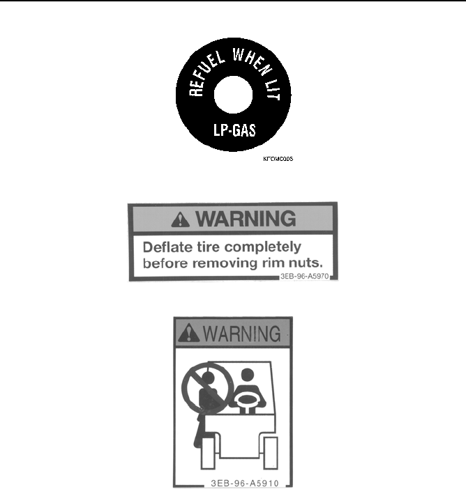
16. SAFETY LABELS
2-36
11. LPG LOW FUEL ALARM LIGHT (On dashboard to left of steering column) (OPTION)
12. Warning for use of split rim (pneumatic tires only) (decal). (Part No. 3EB-96-A5970)
13. No one is permitted to ride the lift truck together with the operator. (Part No. 3EB-96-A5910)

16. SAFETY LABELS
2-37
14. Prohibit the operator from riding on the forks and lifting or lowering himself. Never enter the area under the
forks. (Part No. 3EB-96-A5920)
15. Do not put your hand on the mast! (Warning to avoid getting hand caught) (Part No. 3EB-96-A5940)
NOTES:

READ AND FOLLOW ALL SAFETY PRECAUTIONS.
FAILURE TO DO SO MAY RESULT IN SERIOUS
INJURY OR DEATH.
OPERATION

17. OVERVIEW OF LIFT TRUCK
3-1
17. OVERVIEW OF LIFT TRUCK
17.1 GENERAL VIEW OF LIFT TRUCK
1. Mast 9. Turn signal lamp (option)
2. Lift-chain 10. Head lamp (option)
3. Lift cylinder 11. Operator’s seat
4. Back rest 12. Engine hood
5. Tilt cylinder 13. Counterweight
6. Fork carriage 14. Rear wheel
7. Fork 15. Front wheel
8. Head guard

17. OVERVIEW OF LIFT TRUCK
3-2
17.2 INSTRUMENTS AND CONTROLS
See “EXPLANATION OF COMPONENTS” on page 3-4 for details.
1. Dashboard meter panel display (see following page for description)
2. Lift lever
3. Tilt lever
4. Combination light switch (turn-signal lamp and lamp ON/OFF switch)
5. Starting switch
6. Horn button
7. Accelerator pedal
8. Brake pedal
9. Inching pedal (TORQFLOW transmission)
Clutch pedal (clutch-type truck)
10. Tiltable steering wheel lock lever
11. Fuse box
12. LPG low-fuel alarm light (optional)
13. Parking brake lever
14. Forward/Reverse switch
15. HIGH/LOW speed lever (clutch-type lift truck)
16. FORWARD/REVERSE lever (clutch-type truck)

17. OVERVIEW OF LIFT TRUCK
3-3
17.3 METER PANEL COMPONENTS
See “EXPLANATION OF COMPONENTS” on page 3-4 for details.
NOTICE
Method of checking for blown bulbs in warning lamps.
1. Check that all warning lamps light up when the starting switch is turned ON.
2. If any warning lamp does not light up, the bulb for that lamp is blown.
1. Engine water temperature gauge
2. Fuel gauge
3. Brake fluid level warning lamp
4. Engine oil pressure warning lamp
5. Charge warning lamp
6. Hourmeter
7. Failure indicator lamp
8. Sedimenter warning lamp (models FD20/25/30 only)
9. Glow indicator lamp (models FD20/25/30 only)
10. Neutral indicator/ Travel Interlock indicator lamp (Operator Presence System)
12
109876543

18. EXPLANATION OF COMPONENTS
3-4
18. EXPLANATION OF COMPONENTS
The following is an explanation of the devices used to operate the lift truck shown on pages 3-2 and 3-3. To carry
out suitable operations correctly and safely, it is important to understand fully the method of operating the
equipment and the meanings of the displays.
18.1 EXPLANATION OF INSTRUMENTS AND CONTROLS
METER PANEL
See “EXPLANATION OF METER PANEL COMPONENTS” on page 3-9 for details.
LIFT LEVER
This lever raises and lowers the forks.
Lower: Push the lever forward
Raise: Pull the lever back
Remark
The speed when raising the forks can be controlled by the amount
that the lever is operated and the amount that the accelerator pedal
is depressed. The lowering speed can be controlled only by the
amount that the lever is operated.
TILT LEVER
This lever tilts the mast forward and back.
Tilt forward: Push the lever forward
Tilt back: Pull the lever back
Remark
The speed when tilting the mast forward or back can be controlled by
the amount that the lever is operated and the amount that the accel-
erator pedal is depressed.
COMBINATION LIGHT SWITCH TURN SIGNAL AND
LAMP
This switch controls the lamps.
Light Switch
Position 1: “OFF” - Parking lamp (side clearance lamp) and front
lamps are OFF.
Position 2: Parking lamp (side clearance lamp) lights up.
Position 3: Parking lamp (side clearance lamp) stays lighted up, and
front lamp lights up.
Before operating the lift lever, sit in the operator’s seat and check that the surrounding area is safe.
Before operating the tilt lever, sit in the operator’s seat and check that the surrounding area is safe.
KFI03200102

18. EXPLANATION OF COMPONENTS
3-5
Turn Signal Indicator Switch
This switch controls the turn signal indicator.
Left turn (L): Push lever forward
Right turn (R): Pull lever back
Remark
This lever is equipped with an auto-return mechanism, so the lever
will return automatically to the neutral position.
STARTING SWITCH
This switch starts and stops the engine.
Clutch-type lift truck: When starting the engine, place the forward/
reverse control lever and high/low speed control lever at the neutral
position, pull the parking brake lever, and depress the clutch pedal fully.
Then turn the key.
TORQFLOW transmission lift truck: When starting the engine, place the
forward/reverse control lever in the neutral position, pull the parking brake
lever, depress the inching pedal fully, then turn the key.
OFF: Engine stop position
The key can be inserted or removed. The lamps and horn are activated at this position.
ON: Engine running position
Also activates glow plug preheating circuit in diesel engine BX lift trucks.
See “GLOW INDICATOR LAMP” on page 3-11.
START: Position for starting engine
After the engine starts, release the key. It will automatically return to the ON position.
Precautions for restarting the engine (applies to gasoline/LPG engine lift trucks only)
When the engine does not start, return the key from the START position to the OFF position.
With the anti-restart feature installed, the key cannot be turned to the START position again, if it is returned only to
the ON position. Return the key to the OFF position, then restart.
NOTICE
• When the engine is stopped, do not leave the key at the ON position. This will discharge the battery
and make it difficult to start the engine.
• Do not run the starting motor continuously for longer than the times given below.
• Do not turn the key to the START position when the engine is running.
Gasoline and LPG engine lift truck (AX and BX Models) Maximum 5 seconds
Diesel engine lift truck (BX models) Maximum 10 seconds
AB816490B
LEFT
Push Forward
RIGHT
Pull Back

18. EXPLANATION OF COMPONENTS
3-6
HORN BUTTON
Press the button in the center of the steering wheel to sound the horn.
PEDALS
TORQFLOW transmission
(1): Accelerator pedal
(2): Brake pedal
(3): Inching pedal
The inching pedal is used for fine control when driving the lift
truck slowly forward or in reverse for loading or unloading.
Remark
Do not put your foot on the clutch pedal or accelerator pedal
unless necessary for operation.
Clutch-type lift truck
(1): Accelerator pedal
(2): Brake pedal
(3): Clutch pedal
TILTABLE STEERING WHEEL LOCK LEVER
This lever adjusts the position of the steering wheel and locks it into
position after adjustment.
Position (1): Lock is released
Position (2): Lock is applied
Method of adjustment
1. Pull the lock lever up (position (1))
2. Move the steering wheel forward and backward to adjust to the
most suitable position.
3. Pull the lock lever down (position (2)) to lock the steering wheel in
position.
A
1
2
3
B
1
2
3
1
2

18. EXPLANATION OF COMPONENTS
3-7
FUSE BOX
The fuses protect the electrical components and wiring from burning out.
For details on replacing fuses, see “REPLACING FUSES AND RELAYS”
on page 4-30.)
LPG LOW-FUEL ALARM LIGHT (OPTIONAL)
This optional alarm is located on the dashboard near the parking brake
lever. When this light comes on, the level of LPG is low.
PARKING BRAKE LEVER
Position 1: Brake is applied.
When the lever is pulled back, the parking brake is applied and the
front wheels are locked.
Use this when temporarily stopping or parking the lift truck.
Position 2: Brake is released.
When the lever is pushed forward, the parking brake is released.
FORWARD/REVERSE SWITCH
This switch changes the direction of travel (forward/reverse). Use light
finger pressure to operate switch.
F: FORWARD
N: NEUTRAL
R: REVERSE
NOTICE
Always stop the lift truck completely before operating the lever to
change the travel direction.
Remark
The engine is equipped with a neutral safety switch and cannot be started if the lever is not at the n (neutral)
position.

18. EXPLANATION OF COMPONENTS
3-8
HIGH/LOW SPEED LEVER (CLUTCH-TYPE LIFT TRUCK)
This lever is used to change the travel speed range.
(2): High speed
(N): neutral
(1): Low speed
FORWARD/REVERSE LEVER (CLUTCH-TYPE LIFT
TRUCK)
This lever is used to change the direction of travel (forward/reverse).
F: FORWARD
N: NEUTRAL
R: REVERSE
NOTICE
Always stop t3he lift truck completely before operating the lever to change travel direction.
Remark
The engine cannot be started if this lever is not at the N (neutral) position because the truck is equipped with a
neutral safety switch. See “NEUTRAL/TRAVEL INTERLOCK INDICATOR” on page 3-11 for details.
When starting the engine, return this lever to the
neutral position. Always depress the clutch pedal
when operating the lever.
When starting the engine, return this lever to the
neutral position. Always depress the clutch pedal
when operating the lever.

18. EXPLANATION OF COMPONENTS
3-9
18.2 EXPLANATION OF METER PANEL COMPONENTS
See the illustration in “METER PANEL COMPONENTS” on page 3-3 for the locations of the following items.
ENGINE WATER TEMPERATURE GAUGE
Engine cooling water temperature gauge indicates the engine
coolant temperature with a needle.
White range: Coolant temperature is normal
Red range: Coolant is overheated
NOTICE
If the indicator enters the red range, stop operations immedi-
ately and park the truck in a safe place. (.) If Then take correc-
tive actions against engine overheating.
See “ACTION WHEN ENGINE HAS OVERHEATED” on page 3-45.
FUEL GAUGE
Fuel gauge displays the level of the remaining fuel with a needle
indicator. Check the remaining fuel level with the engine starting
switch key in the ON position. If the lift truck is on a slope, the
correct fuel level will not be shown, so always check fuel level when
the lift truck is on level ground.
Position A: Fuel level is low
Position B: Fuel tank is full
Do not use up all the fuel: fill the fuel tank before the fuel runs out.
NOTICE
On LPG or Dual-Fuel equipped trucks, the gauge is partially or completely covered by decals referencing
the LPG tank gauge. (See “SAFETY LABELS” on page 2-31.)
BRAKE FLUID LEVEL WARNING LAMP
If this lamp lights up, check the brake fluid level and add fluid.
NOTICE
Always use genuine Komatsu brake fluid.
ENGINE OIL PRESSURE WARNING LAMP
Engine oil pressure warning lamp indicates whether the engine
lubrication oil pressure is normal or not.
When functioning normally, this lamp lights up when the engine
starting switch key is turned to the ON position and goes off after
engine startup. Should the lamp light up during operation, stop
operations immediately and check the engine lubrication system for
any abnormality.
AD803220
9JL00065
AB
AD803200
AD803190

18. EXPLANATION OF COMPONENTS
3-10
CHARGE WARNING LAMP
Battery charging warning lamp indicates how the alternator is
generating power.
When functioning normally, this lamp lights up when the starting
switch is turned ON and goes off after engine startup.
Should the lamp light up during operation, check the electrical
system for any abnormality.
HOURMETER
Hourmeter begins to work when the engine starting switch key is
turned to the ON position, and indicates the cumulative value of
operating hours. While the hourmeter is in operation, the operation
indicator (hourglass) keeps flashing.
The last digit advances by 1 (meaning 0.1 hour) every 6 minutes
when the starting switch is at the ON or START position.
FAILURE INDICATOR LAMP
The Failure Indicator lamp begins to flash when some abnormality
has occurred in the control system.
If the lamp begins to flash, stop operations promptly and report the
trouble to the administrator, or call your Komatsu Forklift dealer for
technical assistance.
SEDIMENTER WARNING LAMP
(MODELS FD20/25/30)
Sediment warning lamp is used in combination with the
Maintenance lamp (see “MAINTENANCE LAMP (GASOLINE
ENGINE TRUCK)” above).
The Sediment warning lamp indicates that water has accumulated in
the fuel filter.
When functioning normally, this lamp lights up when the engine
starting switch key is turned to the ON position and goes off after
engine startup.
When the lamp lights up during operations, accumulation of drain water in the fuel filter is indicated. If water is left
inside the fuel filter, the fuel injection pump and injection nozzle function will likely be impaired.
See “(DIESEL ENGINE) DRAIN WATER FROM FUEL FILTER” on page 4-23 for details of the method of draining
the water.
AD803180
AD803110
9JL00821
AD803130

18. EXPLANATION OF COMPONENTS
3-11
GLOW INDICATOR LAMP
(MODELS FD20/25/30)
The glow indicator indicates the preheating condition of the engine.
The lamp lights up when the engine starting switch key is turned to
the ON position and goes off when engine preheating is finished.
Start the engine when the lamp goes out.
Lamp ON: Glow plug heating
Lamp OFF: Glow plug preheating completed
NEUTRAL/TRAVEL INTERLOCK INDICATOR
(OPERATOR PRESENCE SYSTEM)
The AX20/BX20 series trucks are equipped with KOPS (Komatsu
Operator Presence System), which includes the neutral safety and
Travel Interlock safety features. When the neutral lamp blinks, it
means that a safety feature has been activated.
Neutral safety ensures that the operator starts the lift truck in
neutral, while Travel Interlock ensures that, during travel, the
operator stays in the operator’s seat and sits using good posture.
When functioning normally, the neutral lamp:
• lights up when the starting switch is turned ON and goes off after engine startup.
• shines steady on when the Forward/Reverse lever is put into Neutral.
When the lamp blinks, either neutral safety or Travel Interlock is indicated.
Neutral Indicator
Normal starting operation: When the operator turns the starting switch ON with the forward/reverse lever in the
neutral position, the neutral indicator lamp (2) turns on steady. After the engine starts and the operator puts the
lift truck into forward or reverse, the neutral lamp turns off.
Improper starting and neutral safety activated: When the operator attempts to start the lift truck in forward or
reverse, the neutral lamp starts blinking and the engine will not start.
To clear the indicator and resume travel:
• Put the forward/reverse lever into neutral (neutral lamp steady on). The lift truck is now ready for travel.
• Start the engine and put the lift truck into forward or reverse (neutral lamp off).
Travel Interlock Indicator
With the starting switch turned ON and the engine running: When the operator sits improperly or leaves the
operator’s seat for three seconds or more, Travel Interlock disables the transmission of engine power, the
neutral lamp starts blinking, and travel is disabled.
To clear the indicator and resume travel:
• Sit in the operator’s seat using good posture.
• Return the forward/reverse lever to the neutral position (neutral lamp steady on).
The lift truck is now ready for travel. Put the lift truck into forward or reverse. It is not necessary to recycle the
starting switch, as the engine will continue to run after Travel Interlock has activated.
OPERATOR PRESENCE SWITCH
This switch is built into the seat and automatically
engages the Operator Presence System when you are not
properly seated in the operator’s seat while traveling.
When the Operator Presence System is engaged, the
Travel Interlock function causes the neutral indicator on
the meter panel to blink, and disables normal travel
operations.
See “TROUBLESHOOTING THE OPERATOR
PRESENCE SYSTEM” on page 3-12.
AD803120
9JL00399
KOPS02
Operator Presence
Switch

18. EXPLANATION OF COMPONENTS
3-12
TROUBLESHOOTING THE OPERATOR PRESENCE SYSTEM
KOPS01A
• Ensure F/R lever is in the
neutral position
• Sit fully in the operator seat,
and fasten the seat belt
N
Are you properly
seated?
POSSIBLE PROBLEMS
• Travel Interlock
indicator is blinking
• Truck won’t start
• Truck won’t travel
Stop truck operations, move the
truck to a safe area and shut down
the engine. Lock and tag the truck,
then call your dealer for service.
To clear the blinking Travel Interlock indicator and resume truck operations:
- Sit securely in the operator’s seat using good posture.
- Place the Forward/Reverse lever in neutral.
If indicator continues to blink, contact your local dealer.
Travel Interlock Indicator
When Travel Interlock indicator is blinking,
power to transmission is disabled and forklift
cannot travel.
NO
YES

19. REMOVAL AND INSTALLATION OF ATTACHMENTS
3-13
19. REMOVAL AND INSTALLATION OF ATTACHMENTS
19.1 SAFETY PRECAUTIONS
1. When working underneath raised load-handling attachments, always secure them to prevent lowering. When
working with lifting equipment (forklifts) never walk or reach under suspended loads. Use only load-bearing
equipment that is in perfect condition (ropes, chains).
2. Secure the truck against accidental movement of truck or attachments when work is being carried out. When
working underneath raised load-handling attachments, always secure them to prevent lowering.
3. When repairing or renewing hydraulic and electrical components, all truck related setting values must be
observed. Under no circumstances may the working speeds be altered (e.g. lift speed, side shift speed).
4. Personnel may not remain in any Danger Zone in which they are at risk due to movement of the truck,
attachments or lift gear, or any Danger Zone into which descending or dislodged parts may fall.
5. Do not climb onto any part of the truck, which is in motion (e.g. mast, carriage).
6. No servicing should be carried out on the hydraulic system until the mast, carriage or relevant component has
been suitably supported or restrained.
19.2 FORKS
1. Lower the carriage until the forks are resting on the ground and the lift chains are still taut.
2. Release the fork stopper.
3. Move the forks toward center. Fit the lower hook into the notch and remove the fork.
4. Replacement is the reverse of the removal procedure. Smear the fork hooks with grease and adjust the fork
width to suit.
Attachments and major components are heavy and can cause serious injury if improperly handled.
Fork
Carriage
Chain
Anchor
Split Pins
Pin
19. REMOVAL AND INSTALLATION OF ATTACHMENTS
3-14
19.3 CARRIAGE
1. Lower the carriage until the forks are resting on the ground.
2. If a side shift carriage is fitted, disconnect the hydraulic hoses at the carriage, draining the fluid into a suitable
container. Plug and seal the opened connections to prevent ingress of foreign matter.
3. Disconnect the lift chains from the carriage and tie the ends of the chain to the outer mast upper cross member.
4. Raise the mast inner section under power until the bottom of the inner section clears the carriage top roller
assemblies.
5. Ensure that the lift chains do not foul during raising.
6. Reverse the truck away from the carriage.
7. Replacement of the carriage is the reverse of the removal procedure. If a side shift carriage is fitted, operate to
both extremes of travel several times to expel air from the system.
19.4 MAST
Prior to removal of the mast, detach the carriage and forks. See paragraph “FORKS“ and “CARRIAGE“ above.
Remove the drive wheels (if required).
1. With the mast vertical, support the mast securely by attaching lifting tackle to the lifting eyes on the upper cross
brace indicated by the crane hook label. Remove tilt cylinder-to-mast pivot pins.
2. Disconnect hydraulic lines from lift cylinders; blank off all open ends to prevent the ingress of foreign matter.
3. Inclining the mast forward a little from its vertical position, remove the differential mounting cap bolts.
4. Reassembly is the reverse of the removal sequence, noting the following:
a. Renew chain anchor spilled pins.
b. Tighten to the correct torque, the mast locking bolts - see the repair manual for torque figures.
c. Lubricate all pivot pins.
d. If any removal of components affecting tilt angles have been carried out, check and adjust tilt angles. See
the repair manual for further information.
Residual oil will be discharged during disconnection.
Ensure that all locking devices are engaged upon assembly of attachment.

19. REMOVAL AND INSTALLATION OF ATTACHMENTS
3-15
19.5 SIDE SHIFT, FORK POSITIONER AND CLAMP ATTACHMENTS
19.5.1 INSTALLATION/ASSEMBLY
The side shift, fork positioner and clamp attachments all have a common method of installation/assembly as
follows:
1. Before installing, inspect the truck carriage to make sure that the locating notches along the top of the truck
carriage are undamaged and that there are no obstructions on the faceplate itself.
2. Place the clamp into an upright position in preparation for mounting it on the truck.
3. Remove the lower mounting hooks from the back of the clamp frame.
4. Attach the two jumper hoses securely to the clamp's check valve before connecting them to the junction block
on the truck carriage.
5. The open line on the top of the valve is the “clamp open“ circuit. The line on the side of the valve is “clamp
close“ circuit.
6. If the hose junction block is located on the upper portion of the truck carriage, do not connect the jumper hoses
to it until the clamp is mounted on the truck. Lay the hoses over the top of the frame. However, if the junction
block is located on the lower portion or in the center opening of the carriage, and thus nearly inaccessible when
the clamp is mounted, attach the jumper hoses securely before installing the unit.
7. Install the clamp on the truck. It may be lifted onto the truck or simply positioned on the floor (and blocked up
under the frame and arms) or placed on a pallet so that the truck may be driven up and the truck carriage
moved under the upper mounting hooks on the frame. Line up the locating lug on the clamp with the center
notch on the truck carriage. (The carriage can be raised into the hooks at this point). Be careful not to pinch,
twist, or otherwise damage the jumper hoses in mounting. After the unit has been placed on the truck, bolt the
lower mounting hooks into position on the lower clamp frame, firmly securing it to the truck carriage.
8. Attach the hoses to the carriage junction block.
9. It is normal at this point to re-check the hoses from the truck valve to the clamp. Make sure that the hoses are
routed correctly, and that all connections are tight. For best results, there should be as few 90 degree bends,
and other similar flow restrictions, as possible in the hydraulic circuits. Check the mounting hooks to be certain
that the clamp is solidly mounted to the truck carriage.
10. Start the truck. Operate the clamping function several times to remove any air trapped in the system. Before
proceeding to the next step, check to make sure that the retaining nuts on the anchor and rod ends of each
clamp cylinder are tight.
11. Adjust the rate of arm travel. When the clamp is correctly adjusted both arms should close together from full
extension at the fastest possible speed and reach their minimum range at the same moment. The speed with
which the arms close is controlled by two restrictor fittings, one located on each cylinder at the rod end.
To equalize arm travel:
a. Open both restrictor fittings completely by loosening the lock nut and backing out the threaded shaft. The
restrictor is wide open when 1/2 inch of the shaft is exposed above the tightened lock nut. Opening the
valves completely before making the adjustment is important, because the speed of clamp operation is
directly affected by the degree of restriction in the lines. The fittings should be as wide open as possible
with both arms operating at the same
speed.
b.
Close the arms from their full extension, watching to see which one is closing most rapidly.
c. Close the restrictor fitting on the cylinder controlling the faster arm until both arms are travelling at the
same rate. The clamp will probably have to be opened and closed several times to make this adjustment
accurately.
4. To complete installation, insert a hydraulic pressure gauge into the truck system's test port and adjust the
pressure relief setting. Never exceed maximum operating pressure for this clamp.
19.5.2 REMOVAL
Removal is the reverse of the installation/assembly sequence noting all the safety precautions in paragraph 1.
Ensure that all locking devices are engaged upon assembly of attachment.

20. OPERATOR’S COMPARTMENT
3-16
20. OPERATOR’S COMPARTMENT
20.1 ADJUSTING THE SEAT POSITION
It is possible to slide the seat forward or backward to set it to the
optimum position.
Pull lever (1) left. (In this condition, the seat slides forward or
backward.)
NOTICE
Set the seat to the optimum position, then release lever (1).
In this condition, the seat is locked in position.
Fore-and-aft adjustment: 5 in. (127 mm)
20.2 ADJUSTING THE RECLINING ANGLE
(OPTIONAL SUSPENSION SEAT)
With the suspension seat, it is possible to adjust the suspension to match the operator’s weight in addition to
adjusting the fore-and-aft position and reclining angle.
1. Pull up the lever. (When the lever is raised, the angle of the seat
back can be adjusted.)
2. Adjust the angle of the seat back to a position where operation is
easy, then release the lever.
After adjusting, move the seat lightly to the front and rear to check
that it is securely locked in position.
• Adjust the seat before starting operations or when changing operators at the beginning of a
shift. (Always stop the lift truck before adjusting the seat.)
• Adjust the seat to a position where it is possible to depress the brake pedal fully with your
back against the backrest of the operator’s seat. (Always stop the lift truck before adjusting
the seat.)

20. OPERATOR’S COMPARTMENT
3-17
20.3 ADJUSTING THE SUSPENSION
(OPTIONAL SUSPENSION SEAT)
1. Turn the adjustment knob on the right side of the operator’s seat to
adjust the suspension to match your weight in kilograms.
2. Use the needle indicator and scale located on the front seat near the
adjustment knob as a guide when setting the suspension.
Adjust as follows:
To INCREASE the weight setting, turn to (B)
To DECREASE the weight setting, turn to (A)
(Weight adjustment range: 110 - 265 lbs. (50 - 120 kg)
20.4 FITTING AND RELEASING THE SEAT BELT
(Standard and suspension-style seats; suspension-style seat shown here)
1. Pull the belt out of the holder at the right side of the seat, then insert
the tongue into the buckle until it clicks (once it clicks, the seat belt is
in the locked position).
The seat belt is designed to hold the operator stationary when the
holder senses a hard pull.
2. The seat belt may occasionally bind in its holder. If this happens, hold
the belt tongue with both hands, pull it up strongly, then pull the belt
out slowly.
3. To unlatch the belt, hold the tongue portion of the belt with your right
hand, then press the red button in the buckle with your left hand.
4. Continue to hold the belt and let it retract slowly into the holder.

21. ENGINE HOOD
3-18
21. ENGINE HOOD
21.1 OPENING THE ENGINE HOOD
1. To prevent the hood from touching the steering wheel, lift the tilt
steering wheel lock lever (1) and push the steering wheel to the
most forward position (2), then return the lock lever to its original
position (3).
2. Lift the lever (4) on the front left side of the engine hood with your left
hand, and release the hood from the frame.
3. Lift the hood all the way up (5) until the engine hood stopper fits into
place.
On trucks equipped with LPG capability, the seat back folds forward
to clear the tank bracket.
On LPG trucks using the optional folding tank bracket, the bracket
folds away allowing more clearance when the hood is in the UP
position.
Be careful not to get your hand caught when opening or closing the hood.

21. ENGINE HOOD
3-19
21.2 CLOSING THE ENGINE HOOD
1. Lift the engine hood up slightly with your right hand, push in the stop-
per with your left hand, then lower the engine hood slowly and check
that the lock is applied.
2. Lift the steering wheel lock lever, pull the steering column back to its
original position, then return the lock lever to its original locked posi-
tion.
21.3 FORK STOPPER
LOCK position
The forks are secured to the fork carriage. Always use this position
during operations.
FREE Position
The forks can be moved to the left and right, so it is possible to adjust
the spread of the forks to match the size of the load.
NOTICE
See “FORK SPREAD ADJUSTMENT” on page 3-37 for details
about the adjustment method.
Be careful not to get your hand caught when opening or closing the hood.
It is dangerous to operate the lift truck with the steering column pushed forward because the
steering wheel will not be fixed in position. Always be sure to return the steering column to its
original position and check that the lock is securely applied.

22. TRAVEL OPERATIONS
3-20
22. TRAVEL OPERATIONS
22.1 CHECK BEFORE OPERATION
Check the lift truck thoroughly. If any abnormality is found, always repair it or consult your Komatsu Forklift dealer.
22.1.1 CHECK BEFORE OPERATION WITH STARTING SWITCH OFF
n CHECK FOR OIL OR FUEL LEAKAGE, AND BATTERY FLUID LEAKAGE
Check for leakage by conducting a walk-around check.
Check the following items in particular:
• Tubing
• Hydraulic unit
• Cylinder
• Control valve
• Battery
• LPG fuel system connections and fuel level
n CHECK FOR CRACKS AND DAMAGE
Visually check for cracks and damage.
Particularly check the following items.
• Head guard
• Fork
• Load back-rest
• Fork carriage
• Mast
• Fuel tank, LPG fuel tank and connections
n CHECK TIRES AND RIMS (Pneumatic tire lift truck only)
Check the tires and rims for the following items.
• Whether the tire pressure matches the specified pressure:
Front tires: 100 PSI (0.69 MPa) (7.0 kgf/cm
2
)
Rear tires: 100 PSI (0.69 MPa) (7.0 kgf/cm
2
)
• Check that there are no loose lug nuts or rim mating nuts.
• Never operate the lift truck before the check operation is completed.
• If any abnormality is found during the checking, immediately consult a Komatsu Forklift
dealer and do not operate the lift truck until repaired.
• Oil or fuel leakage can cause a lift truck fire. Check for any fluid or LPG leakage before
starting.

22. TRAVEL OPERATIONS
3-21
Tightening Torque
*1
: Pneumatic tire lift truck only.
*2
: Except for 3-ton lift truck (uses different style rim).
n CHECK OIL LEVEL IN HYDRAULIC TANK
1. Lower the forks fully to the floor and stand the mast vertically (perform on flat floor).
2. Open the engine hood and remove the dipstick (combined with breather) on the right side of the lift truck.
(Diesel engine shown at right; gasoline engine similar.)
3. Wipe off hydraulic oil with a clean cloth and insert dipstick into
the tank.
4. Take out the dipstick again and check to see if it indicates the
proper level.
5. If the oil level is low, add genuine Komatsu oil through the filler.
NOTICE
Always use genuine Komatsu hydraulic oil.
n CHECK OIL LEVEL IN BRAKE RESERVOIR TANK
1. Remove the floor plate.
2. Remove the connector of the brake fluid level sensor,
then remove the cap (1). The oil level should be in the
correct range.
Correct range (A): The oil should be within a range of
0.7 in. (18 mm).
3. If the oil level is low, add genuine Komatsu brake fluid.
NOTICE
Always use genuine Komatsu brake fluid.
4. Install the cap.
5. Install the floorboard and close the engine hood.
Check item AX lug (hub) nut tightening torque
AX rim mating nut tightening torque
*1
Front wheels 114 - 180 ft/lb (154 - 245 Nm) (16 - 25 kgfm)
65 - 91 ft/lb (88 - 123 Nm) (9 - 12.5 kgf)
Rear wheels 61 - 108 ft/lb (83 - 147 Nm) (8.5 - 15 kgfm) 44 - 55 ft/lb (59 - 74 Nm) (6 - 7.5 kgfm)
Check item BX lug (hub) nut tightening torque
BX rim mating nut tightening torque
*1
Front wheels 217 - 361 ft/lb (294 - 490 Nm) (30 - 50 kgfm)
145 - 217 ft/lb (196 - 294 Nm) (20 - 30 kgfm)*
2
Rear wheels 145 - 181 ft/lb (196 - 245 Nm) (20 - 25 kgfm) 65 - 91 ft/lb (88 - 123 Nm) (9 - 12.5 kgfm)
• Tighten the lug nuts to the specified torque. (See “SERVICE DATA” on page 4-6 for tightening
torque.)
• Check the tires for excessive wear, damage, and adhesion of foreign matter.
• Check the tires for deformation or damage.

22. TRAVEL OPERATIONS
3-22
n CHECK BATTERY ELECTROLYTE LEVEL
If the battery electrolyte is below the top of the electrode plates, add
distilled water to the top of the electrode plates.
Check the battery case for cracking and stain caused by electrolyte
leakage.
Clean the battery cap breathers and terminals.
NOTICE
• If the battery electrolyte has spilled and the level has gone
down, have your battery repair shop add dilute sulfuric acid of
the same density.
• Do not use a metal funnel when using distilled water or dilute sulfuric acid.
n CHECK PARKING BRAKE
The operating effort for the parking lever should be 55 ft/lb (245 N)
(25 kgf). If it is less then 44 ft/lb (196 N) (20 kgf), please contact your
Komatsu Forklift dealer.
n CHECK HORN
Check that the horn sounds normally when the horn button is
pressed.
n CHECK LAMPS
Check that the head lamps and turn signal lamps work properly. Check lamps also for any dirt or damage.
n CHECK OIL LEVEL IN CLUTCH RESERVOIR TANK
1. Open the inspection cover in the floorplate.
2. Remove the cap and the center cover, and check that the oil
level is within the correct range of 0.39 in. (10 mm) from the cap
as shown.
3. If the oil level is low, add genuine Komatsu brake fluid.
NOTICE
Always use genuine Komatsu brake fluid in the clutch reservoir
tank.
4. Install the cap and the center cover.
NOTICE
Install the center cover with the embossed letters facing up.
5. Close the inspection cover in the floorplate, and fit the floor mat back into place.
• Battery electrolyte is dangerous. If it gets in your eyes or on your skin or clothes, wash it off
with large amounts of water. In particular, if it gets in your eyes, consult a doctor quickly.
• To avoid gas explosions, do not smoke or cause short circuits or sparks near the battery.
AE803050

22. TRAVEL OPERATIONS
3-23
n CHECK PEDALS
Depress the pedal and check that there is no abnormal heaviness or catching.
BRAKE PEDAL
INCHING PEDAL
Remark
The interconnected travel is the distance that the brake pedal and inching pedal move together.
n CHECK DEFLECTION OF DRIVE BELT
Push the belt at the mid-point between the pulleys with your finger
and check that the deflection is the specified value.
NOTICE
Replace the belt if the belt is stretched and there no allowance for adjustment, or if the belt is cut or
cracked.
n CHECK OIL LEVEL IN ENGINE OIL PAN
Use the dipstick to check that the oil is within the correct range. If the
oil level is low, add engine oil through the oil filler.
NOTICE
• If the oil is markedly dirty or discolored, change the oil.
• Always use genuine Komatsu engine oil.
(See “LUBRICANT LIST” on page 4-2).
Play 0.51 - 0.67 in. (13 - 17 mm)
Pedal height when
depressed (h)
3.54 - 3.94 in. (90 - 100 mm)
Play 0.08 - 0.12 in. (2 - 3 mm)
Interconnected travel 1.85 - 2.09 in. (47 - 53 mm)
AX/BX Gas and LPG
0.43 - 0.51 in. (11 - 13 mm)
(98 N finger pressure)
(10 kgf finger pressure)
BX Diesel
0.39-0.59 in. (10 - 15 mm)
(98 N finger pressure)

22. TRAVEL OPERATIONS
3-24
n CHECK COOLANT LEVEL
NOTICE
Even if coolant level in sub-tank is normal, check radiator coolant level every month or 200 hours on hour
meter. If radiator coolant level is lower than specified, that may make overheating likely.
Check radiator and hoses for any water leakage.
Check that coolant in reservoir is cold, and add coolant to MAX
level.
If reservoir is dry, add coolant to radiator and then to reservoir tank.
Also check deflection of V-belt. (See “CHECK DEFLECTION OF
DRIVE BELT” on page 3-23.)
n CHECK ABNORMALITIES FOUND ON PREVIOUS DAY
If any abnormality was found during the checks or operation on the
previous day, check that the repairs have been carried out and that
there is no abnormality.
NOTICE
On LPG trucks, open the Fuel Service Valve, on the tank, by turning it gently counterclockwise.
Turning the valve clockwise shuts off the LPG flow to the engine.
22.1.2 CHECK AFTER STARTING WITH STARTING SWITCH ON
This switch starts and stops the engine. (See “STARTING ENGINE” on
page 3-30.)
When starting the engine, place the forward/reverse control lever at the
neutral position, pull the parking brake lever, and depress the inching
pedal fully, then turn the key.
OFF: Engine stop position
The key can be inserted or removed. The lamps and horn are activated
at this position.
ON: Engine running position
Also activates glow plug preheating circuit in diesel engine BX lift trucks.
See “GLOW INDICATOR LAMP” on page 3-11.
START: Position for starting engine
After the engine starts, release the key. It will automatically return to the ON position.
• Normally, do not open the radiator cap. Check the coolant when the engine is cold, and check
using the reservoir tank.
• NEVER remove the radiator or sub-tank cap when the coolant is hot. Boiling water may
spurt out.
• When removing the radiator cap after the coolant temperature has gone down, turn the cap
slowly to release the pressure before removing it.

22. TRAVEL OPERATIONS
3-25
Warming up the engine
Let the engine warm up for five or six minutes. On LPG trucks, do not depress the accelerator too far after starting
or during warm-up. This may cause freezing of the regulator and/or damage to the engine.
Precautions for restarting the engine (Applies to gasoline and LPG engine lift trucks only)
When the engine does not start, return the key from the START position to the OFF position.
With the anti-restart feature, the key cannot be turned to the START position again from just the ON position.
Return the key to the OFF position and then restart.
NOTICE
Read “16.2 MOUNTING/DISMOUNTING”, “16.3 OPERATOR’S SEAT POSITION ADJUSTMENT” and “16.4
PLACING LIFT TRUCK IN MOTION”, then check the following items.
n CHECK FOR ABNORMAL NOISE, ABNORMAL VIBRATION
Check in particular that there is no abnormal noise or abnormal vibration from the engine or hydraulic pump.
n CHECK ENGINE EXHAUST GAS COLOR
No color, light blue: Normal
Black: Incomplete combustion
White: Oil leaking into cylinder
n CHECK FUEL LEVEL IN FUEL TANK
NOTICE
Never use any fuel mixed with kerosene (diesel engine lift truck).
If the fuel gauge indicator is at the (A) position, the tank is full.
If the fuel level is low, stop the engine and fill the tank through
the fuel filler port.
See “LUBRICANT LIST” on page 4-2 for details of the fuel to
use.
When adding fuel, remove all dirt from around the cap and be
careful not to let any dirt get into the tank.
After adding fuel, tighten the fuel filler cap securely and wipe up
any fuel that was spilled.
LPG engine lift trucks
Check the fuel gauge indicator on the LPG tank.
When adding fuel, never let the fuel overflow. This may cause a fire. If you spill fuel, clean up any
spillage.

22. TRAVEL OPERATIONS
3-26
n REMOVAL AND INSTALLATION OF LPG FUEL TANKS ON LIFT TRUCK
REMOVING LPG TANK FROM LIFT TRUCK
1. Close fuel service (cylinder) valve (turn clockwise) with
engine running.
2. Let engine run out of fuel in lines before turning OFF ignition
switch.
3. Remove fuel hose connection at tank and release tank
clamp.
4. Remove LPG tank from vehicle and place in designated
area.
INSTALLING LPG FUEL TANK ON LIFT TRUCK
1. Place correct size and type LPG fuel tank onto lift truck.
2. Securely mount the tank while positioning as follows:
a. Locating pin must fit through positioning hole in collar.
b. Slot in footring must fit over keyway.
3. Connect LPG fuel hose to tank securely and open fuel ser-
vice valve SLOWLY to gently equalize pressure.
4. Check for leakage at connections. If leakage is suspected,
check with soapy water and look for bubbles at connections. If leakage is confirmed, turn OFF fuel service
valve, tag truck “OUT OF SERVICE” and have qualified personnel make repairs.
n CHECKS USING GAUGES AND WARNING LAMPS (ENGINE OIL
PRESSURE WARNING LAMP, CHARGE WARNING LAMP)
These lamps should not light up during normal operations.
ENGINE WATER TEMPERATURE GAUGE, TORQUE
CONVERTER OIL TEMPERATURE GAUGE
The indicator should be in the white range.
• Review “SAFETY” Section Warnings before changing tanks.
• Use trained and qualified personnel only.
• NO SMOKING during tank change operation.

22. TRAVEL OPERATIONS
3-27
SEDIMENTER WARNING LAMP (Diesel BX models)
This lamp should not light up. If it lights up drain the water from the
fuel filter. (See “(DIESEL ENGINE) DRAIN WATER FROM FUEL
FILTER” on page 4-23.)
n CHECK STEERING WHEEL
Check the following points.
• Play (the play should be 1.2 - 2.4 in. (30- 60 mm).
• There must be no up-down play.
n CHECK LAMPS AND BACK-UP BUZZER
• Check that the lamps light up correctly. Replace any broken
bulbs.
• For trucks equipped with the back-up buzzer option, check that
the back-up buzzer sounds when the forward/reverse lever is
placed in REVERSE. If the back-up buzzer does not sound
when the forward/reverse lever is placed in REVERSE, carry
out repairs or replacement immediately.
n CHECK LIFT-CHAIN
Check lift-chain tension
1. Lift the forks 4 - 6 in. (10 - 15 cm) from the ground.
2. Check the right and left deflections of the lift-chain by pressing it
at the center. The tension is normal when both deflections are
approximately equal.
3. If the deflections differ from each other, adjust with the nut of the
lift-chain stopper bolt.
• Set the forward/reverse control lever to the
neutral position and apply the parking brake.
Then perform checking.
• NEVER insert feet under the forks.

22. TRAVEL OPERATIONS
3-28
Check elongation of the lift-chain
Measure the length over 17 links and check that the length is within
the following specified value.
Replace the chain if the measurement value exceeds this range
The elongation of the lift-chain can be checked with the following
“chain wear scale” also.
Regular inspection and lubrication of the chains will increase their
service life and reduce downtime.
If the chains stretch beyond the recommended amount, they should
be replaced in pairs. Chain stretch can be measured with chain
wear scale part no. 661923.
Measure the chains according to the instructions printed on the
chain wear scale, without a load on the carriage.
To check the hoist chains, raise the carriage 12.0 in. (30 cm) off the
ground to put tension on the chains.
Check the lift-chain lubricant
NOTICE
Use genuine Komatsu engine oil. (See “LUBRICANT LIST” on page 4-2.)
22.1.3 CHECKS WHILE ADVANCING SLOWLY
n CHECK STEERING WHEEL OPERATION
Check the following items while advancing slowly.
• No deviation of steering wheel.
• No unstable steering in straight travel.
• No feeling of abnormally heavy steering when the steering wheel is turned.
n CHECK BRAKE OPERATION
Check the following items by depressing the brake pedal to apply the brake while advancing slowly.
• The brake is properly applied.
• The brake is applied uniformly.
n CHECK OPERATION OF CLUTCH PEDAL (CLUTCH-TYPE LIFT TRUCK)
• When the pedal is depressed, the clutch must be completely disengaged with a margin to spare.
• When the pedal is released, there must be no slipping of the clutch.
Length over 17 links
AX models (all) Max. 10.8 in. (275.5 mm)
BX 2.0 and 2.5 ton lift trucks Max. 13.1 in. (332 mm)
BX 3.0 ton lift trucks Max. 21.7 in. (550 mm)
• The lift-chain is liable to break if heavily rusted.
• If lubrication is insufficient, apply engine oil to prevent rusting.
• Visually check the lift-chain for damage or cracks. If any abnormality is found, consult your
Komatsu Forklift dealer.

22. TRAVEL OPERATIONS
3-29
n CHECK OPERATION OF INCHING PEDAL (TORQFLOW TRANSMISSION LIFT TRUCK)
• Depress the pedal slightly (partially engage the transmission) and check that it is possible to carry out
inching.
• Check that the lift truck stops when the pedal is completely depressed.
n CHECK FOR ABNORMAL NOISE, ABNORMAL SMELL
• Check that there is no abnormal noise or abnormal smell when traveling at low speed.
• Check for odor of LPG, on LPG equipped lift trucks.
22.1.4 CHECKS WHILE OPERATING CONTROL LEVERS
n CHECK OPERATION OF WORK EQUIPMENT
Operate the work equipment control levers from the operator’s seat and check that the forks can be raised and
lowered and that the mast can be tilted forward and back smoothly.
If there is any abnormality, please contact your Komatsu Forklift dealer immediately.
n CHECK FOR ABNORMAL NOISE, ABNORMAL SMELL
Operate the work equipment control levers from the operator’s compartment and check that there is no
abnormal noise or abnormal smell during travel.
22.2 MOUNTING/DISMOUNTING
Mount and dismount facing the lift truck, using the foot of the
head guard as shown in the illustration.
• Always mount/dismount only after first
completely stopping the lift truck.
• NEVER jump on or off the lift truck as this is
very dangerous.

22. TRAVEL OPERATIONS
3-30
22.3 TRAVELING
22.3.1 STARTING ENGINE
1. Set the forward/reverse control lever and high/low speed control
lever to the neutral position.
2. Pull the parking brake lever.
3. Depress the clutch pedal (clutch-type lift trucks) or inching pedal
(TORQFLOW transmission lift trucks).
• Do not attempt to start the engine by short-circuiting the engine starting circuit. Such an act
may cause serious bodily injury or fire.
• When placing lift truck in motion, check that the area around the lift truck is safe and sound
the horn before starting.
• Do not allow anyone to enter the area around the lift truck.
• There is a blind-spot behind the lift truck, so be particularly careful when traveling in reverse.
• When starting the engine, set the forward/reverse control lever and high/low speed control
lever (clutch-type lift truck) to the neutral position and pull the parking brake lever, then
depress the clutch pedal (inching pedal for lift trucks with torque converter) and start engine.

22. TRAVEL OPERATIONS
3-31
4. Gasoline engine lift truck: Depress the accelerator pedal fully,
then slowly release it. (If the engine is warmed up, there is no need
to depress the accelerator pedal.) With the accelerator pedal
released, turn the starting switch to the START position to start the
engine.
LPG engine lift truck: Open fuel service valve at tank. Turn ignition
switch to START position without depressing the accelerator pedal.
As the engine starts, depress accelerator pedal gently. Do not
depress pedal too far until warmed up.
Diesel engine lift truck: Turn the starting switch to the ON position. When the glow plug lamp goes out, turn
the key to the START position without using the accelerator pedal. Allow the key to return to the ON position
after the engine has started.
5. When the engine starts, release the key. (The key will return automatically to the ON position.)
6. Carry out the warming-up operation as directed below.
Gasoline engine lift truck: Warm up the engine for approximately 1 minute, then depress the accelerator
pedal slightly and release it. If the ambient temperature is high, depress the accelerator pedal lightly after
starting, then release it. The engine speed will go down, and this will make it possible to carry out the warming-
up operation more quietly, and will also save fuel.
LPG engine lift truck: If engine does not start easily, do not “pump” the pedal or hold it open during starting to
avoid damage to the regulator and the engine. Wait for about 2 minutes and retry.
Diesel engine lift truck: Let the engine idle for a full 60 to 90 seconds without using the accelerator pedal.
NOTICE
• Do not run the starting motor continuously for longer than the times given below.
• If the engine does not start, wait for at least 20 seconds (LPG engine - wait 2 minutes) before trying
to start again.
• Do not turn the key to the START position when the engine is running.
22.3.2 TRAVEL INTERLOCK
(OPERATOR PRESENCE SYSTEM)
This is a safety feature of the Operator Presence System. (See
“NEUTRAL/TRAVEL INTERLOCK INDICATOR” on page 3-11 and
“TROUBLESHOOTING THE OPERATOR PRESENCE SYSTEM”
on page 3-12.)
When you operate the lift truck using bad seating posture and your
weight is not fully applied to the seat, such as when standing up or
leaning forward or sideways, Travel Interlock engages within three
seconds and cuts off transmission of engine power. The truck will
not move even if you depress the accelerator pedal or operate the forward/reverse lever. While the Travel Interlock
is engaged, the Travel Interlock indicator lamp on the instrument panel blinks. The lamp doubles as the neutral
lamp.
Return to Travel Condition
Seat yourself properly and return the forward / reverse lever to the neutral position to enable the truck for travel
again. Take this step only after you check the surroundings for safety. Travel Interlock does not brake the truck
forcibly.
Gasoline/LPG engine lift truck Max. 5 seconds
Diesel engine lift truck Max. 10 seconds
9JL00399

22. TRAVEL OPERATIONS
3-32
22.3.3 PLACING LIFT TRUCK IN MOTION
Do not rest your feet on the clutch pedal or inching pedal if you are not operating the pedal.
Clutch-type lift truck:
Depress the clutch pedal, set the forward/reverse control lever to the F
or R position, and set high/low speed control lever to position 1.
TORQFLOW transmission lift truck:
Depress the inching pedal and place the forward/reverse control lever at
F or R position.
Release the parking brake and check that the direction of travel and the
area around the lift truck are safe.
Clutch-type lift truck:
Depress the accelerator slowly with your right foot while releasing the
clutch pedal slowly with your left foot.
TORQFLOW transmission lift truck:
Depress the accelerator pedal slowly with your right foot while releasing
the inching pedal slowly with your left foot.
Remark
With the clutch pedal or inching pedal partially engaged, it is possi-
ble to carry out inching.
22.3.4 SHIFTING GEAR (CLUTCH-TYPE LIFT TRUCK)
Release the accelerator pedal and depress the clutch pedal at the same
time.
Shift the high/low speed control lever as shown. When it meshes,
gradually release the clutch pedal while depressing the accelerator
pedal.

22. TRAVEL OPERATIONS
3-33
22.3.5 SHIFTING DIRECTION (CLUTCH-TYPE LIFT TRUCK)
Always stop the lift truck completely before shifting between forward and
reverse.
Stop the lift truck completely. (See “TEMPORARY STOPPING AND
PARKING” on page 3-36 for details of the method of stopping the lift
truck.)
Move the forward/reverse control lever from F to R.
Or move the forward/reverse control lever from R to F.

22. TRAVEL OPERATIONS
3-34
22.4 STARTING AND INCHING ON SLOPE
1. When starting the lift truck on a slope, first pull parking brake
lever (1) and check that the lift truck is held in position.
Depress accelerator pedal (4) a little at a time (for the clutch-
type lift truck, release the clutch pedal at the same time), then
release parking brake lever (1) slowly so that the lift truck starts
up the slope.
2. When the lift truck starts to move up the slope, release parking
brake lever (1) fully. Adjust the uphill travel speed with
accelerator pedal (4).
3. When slowing down or stopping on slopes, gradually release
accelerator pedal (4) (on the clutch-type lift truck, depress the
clutch pedal at the same time), and depress brake pedal (3) just
before stopping.
4. After stopping the lift truck, always pull parking brake lever (1)
fully.
NEVER carry out inching by depressing the accelerator pedal fully and then adjusting the amount the
brake pedal is depressed.

22. TRAVEL OPERATIONS
3-35
22.5 TURNING
Operate the steering wheel with the left hand.
When turning, keep to the inner side when advancing and outer side
when reversing, considering the properties of the rear steering
system.
Use great care to prevent the outside of the counterweight hitting against objects when turning.
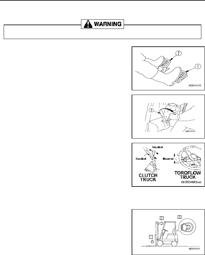
22. TRAVEL OPERATIONS
3-36
22.6 TEMPORARY STOPPING AND PARKING
1. Clutch-type lift truck:
Release the accelerator pedal, depress brake pedal (1), then
depress clutch pedal (2) immediately before the lift truck stops.
TORQFLOW transmission lift truck:
Release the accelerator pedal, then depress brake pedal (1)
2. After the lift truck stops, pull parking brake lever (3) to apply the
parking brake.
After the lift truck stops, return the forward/reverse control lever and
high/low speed control lever (clutch-type lift truck) to the neutral
position.
3. Clutch-type lift truck:
Return both the forward/reverse lever (4) and the high/low speed
lever to the neutral position.
TORQFLOW transmission lift truck:
Return the forward/reverse switch (4) to the NEUTRAL position.
WHEN LEAVING LIFT TRUCK
When leaving the lift truck, always do as follows:
1. Lower the forks to the ground.
2. Tilt the mast until the fork tips touch the ground.
Make sure there is no gap between fork tips and ground, as this will
create a hazard and possibly cause those passing the lift truck to trip
and fall.
3. Turn the starting key to the OFF position, then remove the key.
4. LPG engine trucks: When parking overnight, or for extended
periods, turn off fuel service valve on tank (clockwise) and wait until
engine stops before turning off ignition switch.
Do not park the lift truck on the route of travel for other vehicles or pedestrians.

22. TRAVEL OPERATIONS
3-37
22.7 FORK SPREAD ADJUSTMENT
1. Move the lift truck in front of the load, and stop.
2. Position the mast vertically and lift the forks 4 in. (10 cm)
above the ground.
3. Tilt the mast forward.
4. Move up the fork stopper knob to the free position.
(The forks are movable to left and right at this position.)
5. Adjust the fork spread corresponding to the load size so that
the load center of gravity coincides with the center of the lift
truck.
6. Set the mast vertically, lower the knob and insert the fork
stopper to lock the forks. (The forks are fixed.)
Take extreme care not to get hands or fingers caught while adjusting the fork spread.
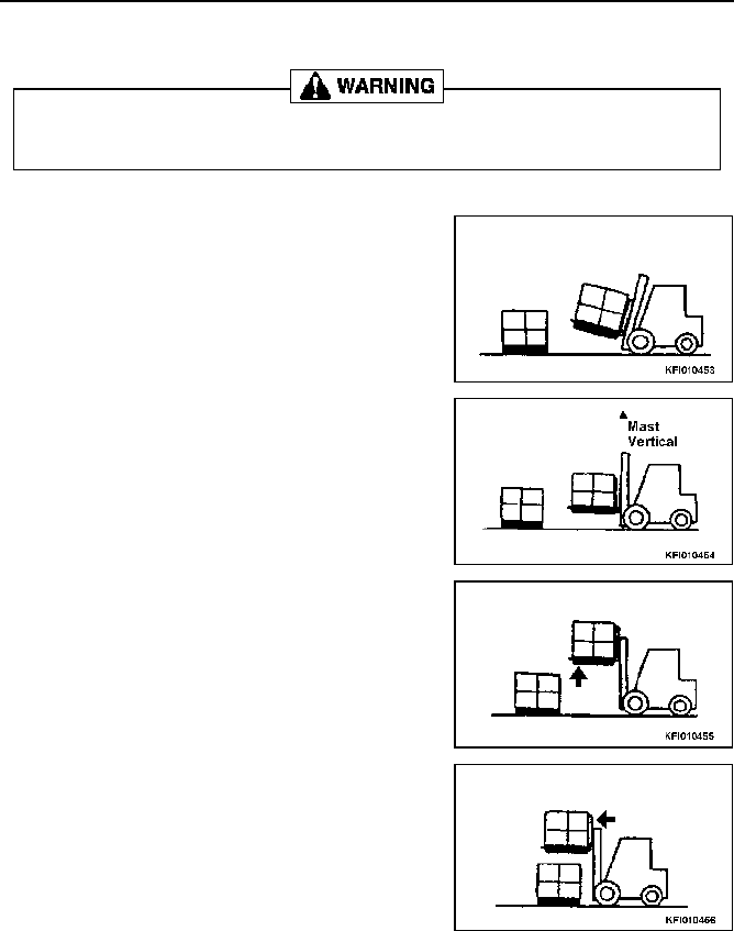
22. TRAVEL OPERATIONS
3-38
22.8 LOAD HANDLING OPERATION
22.8.1 LOADING
1. Stop slowly when reaching the stacking location.
2. Tilt the mast forward until it is vertical.
3. Raise the load to 2 - 4 in. (5 - 10 cm) above the stacking point.
4. Drive slowly forward.
• Check that there is no danger of collapse or breakage of the load at the loading point.
• Check that the loading position is correct.
• Never push the load with the fork tips.

22. TRAVEL OPERATIONS
3-39
5. Lower the load temporarily to the stacking point.
6. Reverse and slowly withdraw the forks 1/4 to 1/3 of the way out
from beneath the load.
7. Raise the load again 2 - 4 in. (5 - 10 cm).
8. Position the load correctly above the stacking point.
9. Lower the load to the correct stacking position.

22. TRAVEL OPERATIONS
3-40
10. Reverse the lift truck slowly and withdraw the forks fully from
beneath the load.
11. Return the mast to the travelling position.
22.8.2 UNLOADING
1. Stop the lift truck squarely in front of the load.
Then bring the mast to a vertical position.
2. Align the forks with the fork insertion point.
• Check that there is no danger of collapse of the load.
• Check that the forks are positioned correctly for insertion under the load.
• Check that the pallet is in a position where it can be lowered completely.

22. TRAVEL OPERATIONS
3-41
3. Drive forward and insert the forks 2/3 to 3/4 of the way under the
load, then raise the load 2 - 4 in. (5 - 10 cm).
4. Reverse slowly 6 - 8 in. (15 - 20 cm).
5. Lower the load slowly.
6. Drive forward slowly and insert the forks fully under the load.
7. Raise the load 2 - 4 in. (5 - 10 cm).

22. TRAVEL OPERATIONS
3-42
8. Reverse the lift truck to a position where the load can be safely
lowered.
9. Lower the load until it is 6 - 8 in. (15 - 20 cm) from the ground.
10. Tilt the mast fully back.
11. Carry the load to the desired location.
22.9 CHECK AFTER OPERATION
On completion of operation, wipe off any dirt and dust. Before storage, check for the following items.
1. Oil leakage, battery fluid or fuel leakage from the units. Check LPG tank connections.
2. Cracks or damage.
3. Check faults found during operation and report them to the person responsible for the lift truck.
4. Lubricate the units (if necessary).

23. COLD WEATHER OPERATION
3-43
23. COLD WEATHER OPERATION
23.1 PREPARATIONS FOR LOW TEMPERATURE
If the temperature drops to colder levels, it becomes difficult to start the engine and the coolant may freeze, so do
as follows:
23.1.1 FUEL AND LUBRICANTS
Change to fuel and oil with low viscosity for all components.
See “LUBRICANT LIST” on page 4-2 for details.
23.1.2 HYDRAULIC OIL
Always use genuine Komatsu oil. This gives better protection against rust than normal hydraulic oil.
23.1.3 COOLANT
NOTICE
When the truck is shipped from the factory, it is filled with low-emission type (non-amine type) glycol-
based coolant. It may be used in ambient temperatures as low as -4°F (-20°C), unless otherwise instructed.
On LPG lift trucks, coolant mixture should test safely down to -35°F (-37°C).
Precautions when handling coolant.
• Coolants are commonly used after being diluted. When diluting coolants, use distilled water or tap water.
• Check that there is no leakage of water from the radiator, water pump, or water hoses.
• Drain all coolant and flush the inside of the system to remove any scale before adding new coolant.
• Do not mix the low-emission type coolant with other conventional coolants for use in the truck.
Glycol-based- Dilution
Use dilution commensurate with the lift truck’s operating environment. Note that the lowest allowable dilution is
30%. Be sure to use dilution percentages higher than 30%.
Table values allow for approximately 2% safety margin as against the standard values.
If coolant percentage exceeds 65%, freezing temperature rises conversely. DO NOT add too much
coolant.
23.1.4 BATTERY
When the ambient temperature drops, the capacity of the battery will also drop. If the battery charge is low, the
battery electrolyte may freeze.
• Maintain the battery charge above 75%, and insulate the battery against cold temperature so that the lift truck
can be started easily in the morning.
• If water is to be added, to prevent freezing, wait until before starting operations the next morning before adding
distilled water.
Proportions of water and antifreeze (or coolant)
Min. temperature °F (°C)
14 (-10) 5 (-15) -4 (-20) -13 (-25) -22 (-30) (-35) (-40) (-45) (-50)
Percentage (%) of Coolant
30 36 41 46 50 54 58 61 64
Coolant is flammable, so keep it away from open flame. Never smoke when handling coolant.

23. COLD WEATHER OPERATION
3-44
23.2 PRECAUTIONS AFTER COMPLETING OPERATIONS
23.2.1 DRAIN WATER
Drain any water accumulated in the fuel system to prevent water from freezing during the night.
23.2.2 ADD FUEL
To prevent moisture from collecting inside the fuel tank, always fill tank after completing operations.
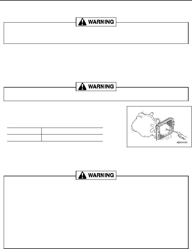
24. HANDLING IN HEAVY-DUTY CONDITIONS
3-45
24. HANDLING IN HEAVY-DUTY CONDITIONS
24.1 PRECAUTIONS WHEN USING IN HEAVY-DUTY CONDITIONS
24.2 CLEAN INSIDE OF COOLING SYSTEM
Scale and rust form easily inside the cooling system, so flush the system with genuine Komatsu radiator rust
prevention fluid, and take other steps to ensure that there is always clean water circulating in the system.
24.3 CLEAN RADIATOR FINS
• If the radiator fins are clogged, it will cause over-heating, so blow
through the radiator fins with compressed air, steam or water.
• When using air or steam, always point the nozzle at a right angle to
the radiator when cleaning.
24.4 CHECK FAN BELT TENSION
If the fan belt is loose, adjust it to the specified tension. A loose fan belt can contribute to overheating.
24.5 ACTION WHEN ENGINE HAS OVERHEATED
Air pressure
142 PSI (0.98 MPa) (10 kg/cm
2
)
Steam pressure
57 PSI (0.39 MPa) (4 kg/cm
2
)
Always wait for the engine to cool down before removing the radiator cap. If you attempt to cool the
radiator too quickly and the radiator cap is removed too soon, hot steam may spurt out and may
cause serious injury.
Dirt may fly and get into your eyes, so always wear protective glasses or goggles.
DO NOT REMOVE THE RADIATOR CAP FROM A HOT RADIATOR! ALWAYS WAIT FOR THE ENGINE
TO COOL DOWN BEFORE REMOVING THE CAP. IF YOU TRY AND REMOVE THE CAP WHILE THE
COOLANT IS HOT, BOILING WATER AND HOT STEAM MAY SPURT OUT CAUSING INJURY.
If the coolant temperature gauge indicator enters the overheat (RED) range, immediately park the lift
truck in a safe place and take the following actions:
1. Keep engine running at low idle, open the engine hood (bonnet) for better airing of the
engine compartment and wait for the engine to cool down. Once cooled down, shut off the
engine. If the engine fan is not turning, shut off the engine immediately and let it cool down
naturally.
2. After the engine has cooled (and is OFF), check the coolant level. Also check for water
leakage from radiator and/or hoses.
If coolant level is low, refill the radiator (first), and sub-tank (second), with cooling water. If water
leakage is discovered, place the lift truck OUT OF SERVICE and contact your Komatsu Forklift dealer
for repairs.

25. LONG-TERM STORAGE
3-46
25. LONG-TERM STORAGE
25.1 BEFORE STORAGE
When putting the lift truck in storage for a long time, do as follows:
• Wash, clean and dry every part, then house the lift truck in a dry building. Never leave it outdoors.
NOTICE
In case it must be left outdoors, park the lift truck on flat, dry ground, and cover it securely with a water-
proof sheet.
• Completely fill the fuel tank, grease all parts, and change the oil before storage.
• Apply a thin coat of grease to the exposed surface of the piston rods of the hydraulic cylinders.
• Disconnect the negative terminal of the battery and cover the battery, or remove the battery from the lift truck
and store it separately.
• If the temperature drops below 32° (0°C), add antifreeze to the cooling water.
• LPG engine lift trucks: Turn off fuel service valve (clockwise) and let engine run out of fuel. Then turn ignition
switch of the OFF position. Remove the LPG tank from the truck and store properly in secured area.
25.2 DURING STORAGE
25.2.1 RUST PREVENTION OPERATION
Operate the engine and move the lift truck for a short distance once a month so that a new film of oil will be coated
over the lubricated surfaces. This prevents loss of the oil film over the long period of storage.
Before operating the work equipment, wipe off the coat of grease from the hydraulic cylinders.
25.2.2 CHARGE BATTERY
Even if the battery is not used, it will naturally discharge if left for a long period. Always charge the battery once a
month.
25.3 AFTER STORAGE
NOTICE
If the lift truck has been stored for a long period without being covered or without carrying out the monthly
rust prevention operation, do as follows before using it.
• Remove the drain plugs from the oil pan and each case, and drain out the water.
• Wipe off the grease from the hydraulic cylinder rods.
• Remove the cylinder head cover, add oil to the valves and rocker arms, and check the operation of the valves.
• After starting the engine, carry out the warming-up operation until the engine oil pressure warning lamp goes
out in order to settle all the parts thoroughly.
If it is necessary to carry out the rust prevention operation while the lift truck is indoors, open the
doors and windows to improve ventilation and prevent gas poisoning.

READ AND FOLLOW ALL SAFETY PRECAUTIONS.
FAILURE TO DO SO MAY RESULT IN SERIOUS
INJURY OR DEATH.
MAINTENANCE

26. OUTLINE OF SERVICE
4-1
26. OUTLINE OF SERVICE
• Use Komatsu Forklift genuine parts for replacement.
• When changing or adding oil, use only the oil that is recommended. Do not use a different kind or grade of oil.
• Unless otherwise specified, the oil and coolant used at delivery from the factory shall be as listed below.
26.1 OIL
• Since the oil is used for the work equipment, etc., under severe conditions (at high temperature and high pres-
sure), it will deteriorate as operating time passes. Always use an oil matching the grade and working tempera-
tures given in the Operation Manual.
• Always replace the oil at specified time intervals even if it is not deteriorated.
• Oil is often compared to human blood. A lift truck should be maintained with the same care taken for the human
body so that impurities (water, metal chips, dust, etc.) do not enter the lift truck system.
• Most lift truck malfunctions are caused by the entry of impurities.
• Take special care to avoid the entry of impurities during storage and lubrication, etc.
• Never blend oils of different grades or brands.
• Add specified volume of oil. Too little or too much oil may both cause problems in the fork lift truck.
• If the oil in the work equipment becomes cloudy, it is likely that air or water have entered the circuit. Consult a
Komatsu Forklift dealer.
• When replacing oil, replace the relevant filters at the same time.
26.2 GREASE
• Grease prevents wear and tear and the generation of squeaking noise from the joints, etc.
• Lift trucks are provided with grease nipples in various places. Some of these are not mentioned in this manual
since they are for overhauling purposes and do not require greasing.
• If friction is noticed in movable parts after operation, grease them.
• After greasing, wipe off any old grease that is forced out, especially on rotating parts that will be worn by adher-
ing sand and dirt.
26.3 OIL STORAGE AND PRESERVATION
• Store and preserve oil so as to prevent entry of dirt, dust, water or other contaminants.
• When storing oil drums for long periods, place them side-by-side with filler sides facing in the same direction.
• If necessary to store drums outdoors, cover them with waterproof sheeting. Ensure that the screw caps
(bung plugs) are tight.
• To prevent oil deterioration during long periods of storage, use drums on a “first-in, first-out” basis.
26.4 FILTERS
• Filters are very important safety items which prevent problems caused by impurities contained in the oil or
hydraulic circuit which sends oil into important units. Periodically replace the filters referring to this manual.
• When replacing oil filters, check for metal powder or shavings deposited on the used filters.
• Do not unpack replacement filters until immediately before installation.
• Always use genuine Komatsu Forklift filters.
Item Type of fluid
Engine oil
SAE 10W30 (gas/LPG)
SAE 30W (diesel)
Differential case SAE 90
Hydraulic tank ISO # 32 Hydraulic Fluid
TORQFLOW transmission case Dexron Automatic Transmission Fluid
Cooling system Fresh water and Glycol-based Coolant
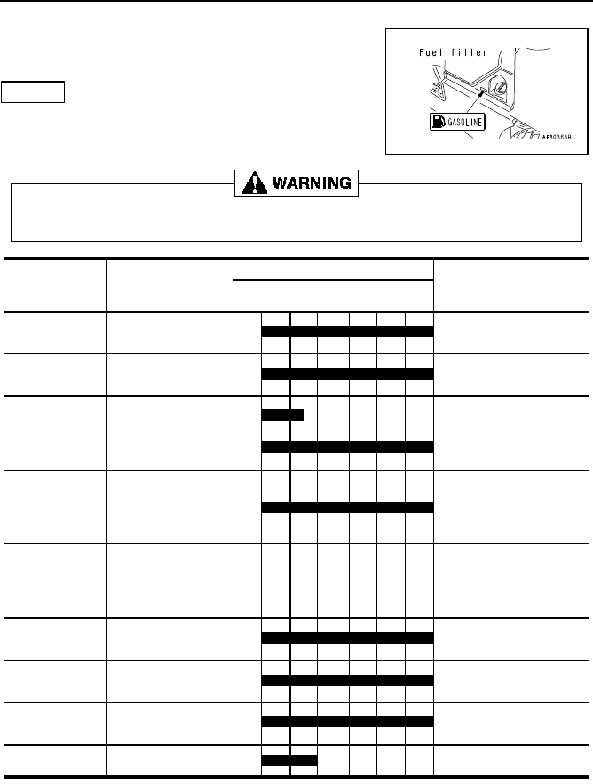
27. LUBRICANT LIST
4-2
27. LUBRICANT LIST
27.1 AX – GASOLINE/LPG ENGINE
MODELS FG15H(S)/18H(S)-17
NOTICE
Always use genuine Komatsu Forklift oil and grease.
Oil and grease are available from your Komatsu Forklift dealer.
Never use the incorrect kind of brake fluid.
Use genuine Komatsu Forklift DOT 3 brake fluid.
Engine oil pan
Engine oil
(SAE10W-30SJ)
(including filter)
4.50 quarts / 4.25 L
TORQFLOW
transmission case
DEXRON automatic
transmission fluid
12.50 quarts / 11.80 L
Differential case
TORQFLOW transmission:
6.00 quarts / 5.70 L
Clutch transmission:
13.74 quarts / 13.00 L
Hydraulic tank
FG15/18HT-17:
7.10 U.S. gal. / 26.90 L
FG15/18ST-17:
5.00 U.S. gal. / 18.90 L
Fuel tank
Gasoline: 87 octane
(recommended)
LPG: 107 octane
propane
FG15/18HT-17:
9.70 U.S. gal. / 36.72 L
FG15/18ST-17:
6.60 U.S. gal. / 25.00 L
Brake system 5.07 oz. / 0.15 L
Greasing points
Lithium grease
(NLGI No. 2)
—
Clutch reservoir
tank (option)
Brake fluid (DOT 3) 0.026 U.S. gal. / 0.100 L
Cooling system
Glycol-based coolant 2.41 U.S. gal. / 10.90 L
Gear oil (SAE80W)
Gear oil (SAE90W)
Hydraulic oil ISO #32
Brake fluid (DOT 3)
(SAE7OR-3)
Ambient Temperature
-4
-20
14
-10
32
0
50
10
68
20
86°F
30°C
Location Type of Fluid Capactities

27. LUBRICANT LIST
4-3
27.2 BX – GASOLINE/LPG ENGINE
MODELS FG20/25/30-14, FG20H/25H/30H-14, FG20S/
25S-14, FG20SH/25SH/30SH-14
NOTICE
Always use genuine Komatsu Forklift oil and grease.
Never use the incorrect kind of brake fluid.
Use genuine Komatsu Forklift DOT 3 brake fluid.
Engine oil pan
Engine oil
(SAE10W-30SJ)
(including filter)
4.50 quarts / 4.25 L
TORQFLOW
transmission case
DEXRON automatic
transmission fluid
12.50 quarts / 11.80 L
Differential case
TORQFLOW transmission:
6.00 quarts / 5.70 L
Clutch transmission:
14 quarts / 13.25 L
Hydraulic tank Hydraulic oil ISO #32
FG20/25/30(H):
14.8 U.S. gal. / 56 L
FG20/25/30S(H):
9.5 U.S. gal. / 36 L
Fuel tank
Gasoline: 87 octane
(recommended)
LPG: 107 octane
propane
FG20/25/30(H):
14.5 U.S. gal. / 55 L
FG20/25/30S(H):
10.6 U.S. gal. / 40 L
Brake system
Brake fluid (DOT 3)
(SAE7OR-3)
16.64 oz. / 0.5 L
Greasing points
Lithium grease
(NLGI No. 2)
—
Clutch reservoir
tank (option)
Brake fluid (DOT 3) 0.026 U.S. gal. / 0.1 L
Cooling system Glycol-based coolant 2.4 U.S. gal. / 9.2 L
Gear oil (SAE90W)
Gear oil (SAE80W)
Ambient Temperature
-4
-20
14
-10
32
0
50
10
68
20
86°F
30°C
Location Type of Fluid Capactities

27. LUBRICANT LIST
4-4
27.3 BX – DIESEL ENGINE
MODELS FD20/25/30-14
NOTICE
Never use fuel mixed with kerosene.
Always use genuine Komatsu Forklift oil and grease.
Never use the incorrect kind of brake fluid.
Use genuine Komatsu Forklift DOT 3 brake fluid.
Engine oil pan
(including filter)
8.0 quarts / 7.6 L
TORQFLOW
transmission case
DEXRON automatic
transmission fluid
12.5 quarts / 11.8 L
Differential case
TORQFLOW transmission:
6.0 quarts / 5.7 L
Clutch transmission:
14.0 quarts / 13.2 L
Hydraulic tank Hydraulic oil ISO #32 14.8 U.S. gal. / 56 L
14.8 U.S. gal. / 56 L
Fuel tank
Diesel fuel
ASTM D975 No. 2
Brake system
Brake fluid (DOT 3)
(SAE7OR-3)
16.64 oz / 0.5 L
Greasing points
Lithium grease
(NLGI No. 2)
—
Clutch reservoir
tank (option)
Brake fluid (DOT 3) 0.104 quart / 0.100 L
Cooling system Glycol-based coolant 2.5 U.S. gal. / 9.5 L
Engine oil
(SAE10W-CD)
Gear oil (SAE80W)
Gear oil (SAE90W)
Engine oil
(SAE30W-30-CD)
ASTM D975 No. 1
Ambient Temperature
-4
-20
14
-10
32
0
50
10
68
20
86°F
30°C
Location Type of Fluid Capactities

27. LUBRICANT LIST
4-5
27.4 OIL AND GREASING CHART
OIL, GREASE LOCATIONS AND INSPECTION AND MAINTENANCE INTERVALS
Check and add fluid if necessary
Change or add oil
Shows the number of places to add oil or grease
Chart symbol Type of fluid
AF Automatic transmission fluid
EO
Diesel engine oil
Gasoline engine oil
MO Engine oil
GO Gear oil
HO Hydraulic oil
BF Brake fluid
GGrease

28. SERVICE DATA
4-6
28. SERVICE DATA
28.1 AX SERVICE DATA – ALL MODELS
* Pneumatic tire lift trucks only
Component Inspection item Unit
FG15H(C)/18H-17
FG15S/18S-17
Engine
Engine
Engine model – NISSAN K21 (4-cyl)
Idling speed rpm 750
Maximum speed rpm 2,950
Compression psi/rpm
Gasoline/Dual-fuel: 178/350
LPG: 185/1,250
Lubricating oil
cooling system
Fan belt deflection in.(mm)
0.43 - 0.51 (11 - 13)
finger pressure: 98 N (10 kgf)
Fuel system
Injection timing
BTDC
deg.
ECU control
Injection order – 1-3-4-2
Injection rail pressure psi 50
LPG maximum tank pressure psi 250
LPG dry gas pressure psi 4.6
Intake/exhaust
system
Valve clearance
Intake
in.(mm) 0.015 (0.38) Warm
Exhaust
Electric system
Electronic ignition air gap in. (mm) 0.0138 - 0.0177 (0.35 - 0.45)
Spark plug gap in.(mm) 0.031 - 0.035 (0.8 - 0.9)
Spark plug type – NGK: FR2A-D
Ignition timing (gasoline)
Ignition timing (LPG)
BTDC
deg.
ECU control
Firing order – 1 - 3 - 4 - 2
Travel system
Tires Tire inflation pressure
Front wheels
psi (MPa)
100 (0.69) (7.0 kgf/cm
2
)*
Rear wheels
Lug (hub) nuts Tightening torque
Front wheels
ft/ibs (Nm)
114 - 180 (154 - 245)
(16 - 25 kgfm)
Rear wheels
61 - 108 ft/lb
83 - 147 Nm (8.5 - 15 kgfm)*
Rim mating nuts Tightening torque
Front wheels
65 - 91 (88 - 123)
(9.0 - 12.5 kgfm)*
Rear wheels 44 - 55 (59 - 74) (6.0 - 7.5 kgfm)*
Steering, braking system
Steering wheel Play
in. (mm)
1.2 - 2.4 (30 - 60)
Clutch pedal Play 0.12 - 0.20 in. (3 - 5 mm)
Inching pedal
Play 0.08 - 0.12 (2 - 3)
Interconnected travel 1.85 - 2.09 (47 - 53)
Brake pedal
Play
in. (mm)
0.51 - 0.67 (13 - 17)
Pedal height when pedal is depressed 3.54 - 3.94 (90 -100)
Brake
Parking brake operating force
ft/lb (Nm)
55 (245) (25 kgf)
Tightening torque for back plate
mounting bolts
108 - 146 (147 - 198)
(15 - 20 kgfm)
Loading equipment
Forks Fork thickness (at base of forks)
in. (mm)
1.5 ton truck: Min. 1.26 (32)
1.8 ton truck: Min. 1.34 (34)
Chain Length over 17 links Max. 10.8 (275.5)
Hydraulic system Relief pressure psi (MPa)
2,611 (18) (185 kgf/cm
2
)

28. SERVICE DATA
4-7
28.2 BX SERVICE DATA – GASOLINE/LPG ENGINE
* Pneumatic tire lift truck only
Component Inspection item Unit
FG20(C)/25(C)-14
FG20S/25S-14
FG20H/25H/30(C)(H)-14
FG20SH/25SH/30SH-14
Engine
Engine
Engine model –
NISSAN K21
(4-cyl.)
NISSAN K25
Idling speed rpm 750
Maximum speed rpm 2,950 2,900
Compression psi/rpm
Gasoline/Dual-fuel: 178/250
LPG: 185/250
Lubricating oil
cooling system
Fan belt deflection in. (mm)
0.43 - 0.51 (11 - 13)
finger pressure: 98 N (10 kgf)
Fuel system
Injection timing BTDC deg. ECU control
Injection order – 1 - 3 - 4 - 2
Injection pressure psi 50
LPG max. tank pressure psi 250
LPG dry gas pressure psi 4.6
Intake/exhaust
system
Valve clear-
ance
Intake
in. (mm) 0.015 (0.38) Warm
Exhaust
Electric system
Spark plug gap in. (mm) 0.031 - 0.035 (0.8 - 0.9)
Spark plug type – NGK: FR2A-D
Ignition timing (gas)
Ignition timing (LPG)
BTDC deg. ECU control
Firing order – 1 - 3 - 4 - 2
Travel system
Tires
Tire inflation
pressure
Front wheels
psi (MPa)
100 (0.69) (7.0 kgf/cm
2
)*
Rear wheels
Lug (hub) nuts
Tightening
torque
Front wheels
lbs/ft (Nm)
217 - 361 (294 - 490)
(30 - 50 kgfm)
Rear wheels
145 - 181 (196 - 245)
(20 - 25 kgfm)*
Rim mating nuts
Tightening
torque
Front wheels
145 - 217 (196 - 294)
(20 - 30 kgfm)*
(excluding 3.0 ton lift truck)
Rear wheels
65 - 91
(88 - 123) (9.0 - 12.5 kgfm)
Steering, braking system
Steering wheel Play
in. (mm)
1.2 - 2.4 (30 - 60)
Clutch pedal Play 0.12 - 0.20 in. (3 - 5 mm)
Inching pedal
Play 0.08 - 0.12 (2 - 3)
Interconnected travel 1.85 - 2.09 (47 - 53)
Brake pedal
Play
in. (mm)
0.51 - 0.67 (13 - 17)
Pedal height when depressed 3.54 - 3.94 (90 - 100)
Brake
Parking brake operating force ft/lb (N) 55 (245) (25 kgf)
Tightening torque for back
plate mounting bolts
lbs/ft (Nm)
108 - 146 (147 - 196)
(15 - 20 kgfm)
Loading equipment
Forks
Fork thickness (at base of
forks)
in. (mm)
2.0 ton truck: Min. 1.42 (36)
2.5 ton truck: Min. 1.58 (40)
3.0 ton truck: Min. 1.58 (40)
Chain Length over 17 links Max. 13.1 (332)
Hydraulic system Relief pressure psi (MPa)
2,610.7 (18) (185 kgf/cm
2
)

28. SERVICE DATA
4-8
28.3 BX SERVICE DATA – DIESEL ENGINE
Component Inspection item Unit FD20/25/30-14
Engine
Engine
Engine model – 4D94E
Idling speed rpm 675 - 725
Maximum speed rpm 2,650 - 2,750
Compression
psi/ rpm
(MPa/rpm)
412 - 441 (min. 340)/250
(2.94/250)
Lubricating oil
cooling system
Fan belt deflection in.(mm)
0.39 - 0.59 (10 - 15)
finger pressure: 98 N (10 kgf)
Fuel system
Injection timing ATDC° 6°
Injection order – 1 - 3 - 4 - 2
Injection pressure psi (MPa) 1,850 (12.75)
Intake/exhaust
system
Valve clearance
Intake
in. (mm) 0.008 (0.20) Cool
Exhaust
Travel system
Tires
Tire inflation
pressure
Front wheels
psi (MPa) 100 (0.69)
Rear wheels
Lug (hub) nuts
Tightening
torque
Front wheels
lbs/ft (Nm)
217 - 361 (294 - 490) (30 - 50 kgfm)
Rear wheels 145 - 181 (196 - 245) (20 - 25 kgfm)
Rim mating
nuts
Tightening
torque
Front wheels
145 - 217 (196 - 294) (20 - 30 kgfm)
(excluding 3.0 ton lift truck)
Rear wheels 65 - 91 (88 - 123) (9.0 - 12.5 kgfm)
Steering, braking system
Steering wheel Play
in. (mm)
1.2 - 2.4 (30 - 60)
Inching pedal
Play 0.08 - 0.12 (2 - 3)
Interconnected travel 1.85 - 2.09 (47 - 53)
Brake pedal
Play
in. (mm)
0.51 - 0.67 (13 - 17)
Pedal height when pedal is
depressed
3.54 - 3.94 (90 - 100)
Brake
Parking brake operating force ft/lb (N) 55 (245) (25 kgf)
Tightening torque for back plate
mounting bolts
lbs/ft (Nm) 108 - 146 (147 - 196) (15 - 20 kgfm)
Loading equipment
Forks Fork thickness (at base of forks)
in. (mm)
2.0 ton truck: Min. 1.42 (36)
2.5 ton truck: Min. 1.58 (40)
3.0 ton truck: Min. 1.58 (40)
Chain Length over 17 links Max. 13.1 (332)
Hydraulic sys-
tem
Relief pressure psi (MPa)
2,610.7 (18) (185 kgf/cm
2
)

28. SERVICE DATA
4-9
28.4 TORQUE LIST
For unspecified bolts and nuts, use the torque specifications in this list.
Select the proper torque corresponding to the width across flats (b) of bolts
and nuts.
When replacing bolts and nuts, always use genuine
Komatsu
Forklift parts
that match the previous installation in size.
Thread diameter
of bolt (mm)
(a)
Width across
flat (mm)
(b)
Tightening torque
ft/lb kgfm Nm
6
8
10
12
14
10
13
17
19
22
9.73 ± 1.03
23.2 ± 2.1
48.5 ± 5.0
82.6 ± 7.2
131 ± 14
1.35 ± 0.15
3.2 ± 0.3
6.7 ± 0.7
11.5 ± 1.0
18.0 ± 2.0
13.2 ± 1.4
31.4 ± 2.9
65.7 ± 6.8
112 ± 9.8
177 ± 19
16
18
20
22
24
24
27
30
32
36
206 ± 21
282 ± 29
405 ± 43
549 ± 58
684 ± 72
28.5 ± 3
39 ± 3
56 ± 6
76 ± 8
94.5 ± 10
279 ± 29
383 ± 39
549 ± 58
745 ± 78
927 ± 98
27
30
33
36
39
41
48
50
55
60
973 ± 100
1,270 ± 140
1,630 ± 180
2,030 ± 210
2,420 ± 250
135 ± 15
175 ± 20
225 ± 25
280 ± 30
335 ± 35
1,320 ± 140
1,720 ± 190
2,210 ± 240
2,750 ± 290
3,280 ± 340

29. PERIODIC REPLACEMENT OF SAFETY CRITICAL PARTS
4-10
29. PERIODIC REPLACEMENT OF SAFETY CRITICAL PARTS
To ensure safety at all times when operating or driving the lift truck, the lift truck user must always carry out periodic
maintenance. In addition, to further improve safety, the user should also perform periodic replacement of parts
given in the table below. These parts, in particular, are closely relate to safety and fire prevention.
The material of these parts may change over time, or they may easily wear or deteriorate. However, it is difficult to
judge the condition of these parts simply by periodic maintenance. The parts listed should always be replaced after
a fixed, specified time has passed, regardless of their condition. This is necessary to ensure that these parts
maintain their full function at all times.
Note that if these parts show any abnormality before the replacement interval has passed, they should be repaired
or replaced immediately.
If the hose clamps show any signs of deterioration, such as deformation or cracking, replace them at the same time
as the hoses.
Note that this periodic replacement is not covered by warranty.
IMPORTANT PARTS LIST
No. Part name
Replacement Period
(Years)
1 Brake valve, wheel cylinder cup and dust seal, etc. 1
2 Brake hose or tube 1 - 2
3 Clutch reservoir tank, tube 2 - 4
4 Power steering hose 2
5 Stop lamp switch (hydraulic type) 2 - 4
6Fuel hose 2
7 Rubber parts inside power steering system 2
8 Lift chain 2 - 4
9 Hydraulic hose for lifting mechanism 1 - 2
Use only genuine fuel hose. If a poor quality hose is used, plasticizer material or other harmful
material from the hose may contaminate the LPG and cause the injection valve to stick. This will
prevent the engine from starting.

30. MAINTENANCE SCHEDULE CHART
4-11
30. MAINTENANCE SCHEDULE CHART
Perform maintenance at intervals of months or operation hours, whichever occurs first.
Service Item (gasoline/LPG/diesel engines)
(#) Indicates Emissions-Related (EPA) Maintenance Service Items
Page
First month or initial 200 hours service (only after the first one month)
Change oil in hydraulic tank, replace line filter, clean strainer, clean inside of tank 4-15
(#) Change oil in engine oil pan and replace engine oil filter cartridge (gasoline and diesel engines) 4-16
(#) Check, adjust engine intake and exhaust valve clearance 4-16
Tighten (retorque) engine cylinder head bolts 4-16
(#) Check air cleaner and replace element/filter if dirty 4-17
(#) Inspect and clean fuel filter sock ( not replaceable) (gasoline engine) 4-17
Change oil in TORQFLOW transmission case and clean TORQFLOW transmission strainer 4-18
Change oil in differential case (includes oil in transmission case on clutch-type lift trucks) 4-18
(#) Check spark plugs for burning of electrode, burning of insulator (gasoline & LP engines) 4-19
Check, adjust alternator belt (drive belt) tension 4-19
Tighten bolts and nuts (especially lug nuts [hub nuts], and overhead guard, load backrest and operator’s
seat mounting bolts and nuts)
4-19
Complete “Check Before Operation” items in previous section of this manual 3-20
Every 2 weeks or every 100 hours service
Grease lift chain 4-19
Every month or every 200 hours service
Check wheel rims for deformation, cracking and damage 4-19
Check wheel bearings for play and abnormal noise 4-19
Check hydraulic cylinders for looseness, deformation, cracking, damage and wear 4-19
Check all piping/tubing/connectors for oil leakage, deformation or damage 4-19
Check operation of hydraulic cylinders 4-19
Check hydraulic drift of lift cylinder 4-19
Check hydraulic drift of tilt cylinders 4-19
Check movement of work equipment control lever(s) 4-19
Check forks and fork stopper for deformation, cracking, damage and wear 4-19
Check forks for unevenness and twisting 4-19
Check mast for deformation, cracking, damage and wear 4-19
Check mast roller for play 4-19
Check chain and chain wheel for deformation, damage, rust and poor lubrication 4-19
Check chain wheel bearing for play 4-20

30. MAINTENANCE SCHEDULE CHART
4-12
Every month or every 200 hours service (continued)
Check chain anchor bolt for deformation and damage 4-20
Check gear box for oil leakage, looseness of mount 4-20
Check mounting condition of power steering, check for looseness at connections 4-20
Check pedals for play, looseness, damage and wear 4-20
Check brake piping/tubing for damage, leakage, looseness, contact, looseness of brake tubing clips
and disconnection at fittings
4-20
Check clearance between brake drum and lining, check brake for grabbing, dragging or pulling 4-20
Check shift lever for play, meshing 4-20
Check for oil leakage from transmission and differential cases 4-20
Check oil level in TORQFLOW transmission, add oil as necessary (do not overfill) 4-21
Clean inside of cooling system 4-22
Check for catching, stalling and knocking when accelerating 4-22
(#) Check air cleaner and replace element/filter if dirty 4-17
Check operation of governor (maximum speed) 4-22
(#) Check piping/tubing and connections/fittings for fuel/gas leakage 4-22
(#) Drain water from fuel filter (diesel engine) 4-23
(#) Check vaporizer for tar, drain (LPG engine) 4-23
Check radiator hoses for cracking, damage 4-23
Check operating condition of radiator cap, check installation 4-23
Check fan for deformation, cracking, and damage 4-23
Check fan for looseness and mounting 4-23
(#) Check, adjust alternator belt (drive belt) tension 4-19
(#) Check spark plugs for burning of electrode, burning of insulator (gasoline/LP engines) 4-19
Change oil in engine oil pan and replace oil filter cartridge (diesel engine) 4-16
Check operation of starting switch, check meshing of pinion gear 4-24
Check level and specific gravity of electrolyte. Check and clean battery caps and terminals. 4-24
Check wiring connections for looseness 4-24
Check overhead guard, load backrest for deformation, cracking, damage and looseness 4-25
Check operator’s seat mount for looseness and damage, (#) check LPG cylinder mounting bracket 4-25
Grease all lubrication points 4-25
Service Item (gasoline/LPG/diesel engines)
(#) Indicates Emissions-Related (EPA) Maintenance Service Items
Page

30. MAINTENANCE SCHEDULE CHART
4-13
Every 500 hours service
Change oil in engine oil pan and replace engine oil filter cartridge (gasoline engine) 4-16
(#) Drain water from fuel filter and replace fuel filter cartridge (diesel engine) 4-26
Every 3 months or every 600 hours service
(#) Clean LPG filter 4-26
(#) Inspect PCV valve and hoses (gasoline engine) 4-27
Grease fuel injection pump governor, change governor oil 4-27
Replace engine oil filter cartridge (diesel engine) 4-16
Check oil level in transmission case, add oil as necessary (clutch-type trucks, include differential case) 4-21
Check oil level in differential case, add oil as necessary (clutch-type trucks, include transmission case) 4-27
Every 1,000 hours service (EPA and Diesel engines)
Check and adjust fuel injection pressure and atomizing condition of nozzles 4-27
Every 6 months or every 1,200 hours service
Check steering link for bending, damage and wear 4-27
Check steering knuckle for play, deformation and damage 4-27
Check for marked variation in minimum turning radius 4-27
Change oil in differential case (clutch-type lift trucks, include transmission case) 4-18
Change oil in TORQFLOW transmission case 4-18
Clean TORQFLOW transmission strainer 4-18
Replace torque converter oil filter 4-28
Change clutch oil 4-28
Change brake oil/fluid 4-28
(#) Adjust intake and exhaust valve clearance 4-16
Measure compression pressure 4-28
(#) Check, adjust fuel injection timing, check and inspect fuel injection nozzles (diesel engine) 4-28
(#) Check PCV blow-by gas reduction system for clogging, damage (gasoline engine) 4-28
Clean inside of cooling system 4-22
Clean radiator 4-22
Change oil in hydraulic tank, replace hydraulic line filter, clean hydraulic tank strainer, clean inside of
hydraulic tank
4-15
Service Item (gasoline/LPG/diesel engines)
(#) Indicates Emissions-Related (EPA) Maintenance Service Items
Page

30. MAINTENANCE SCHEDULE CHART
4-14
Every 2,000 hours service
(#) Check and adjust fuel injection timing (diesel engine) 4-28
Replace LPG mixer air valve diaphragm, under normal operating conditions. Replace more often in cold
or severe service applications. Replace O-ring for LPG tank valve.
4-28
Every 12 months (year) or every 2,400 hours service
Check operation of brake master cylinder, check for oil leakage, damage and wear 4-28
Check operation of wheel cylinders, check for oil leakage, damage and wear 4-28
Check operation of brake drum, check for damage and wear 4-28
Check brake linings for wear 4-28
Check operating condition of brake shoes 4-28
Check brake adjustment lever and ratchet for wear and damage 4-28
Check brake springs for deterioration 4-28
Check brake back plates for deformation and cracking, check mounting condition 4-28
Check air tightness of brake piping/tubing 4-28
Check axle for deformation, cracking and damage 4-28
Check mounting condition of differential 4-29
Check root (base) of forks for cracking (use color check) 4-29
Check roller shaft of loading equipment for cracking and damage 4-29
Check mast support for damage and wear 4-29
Check operation of relief valve, check relief pressure 4-29
(#) Replace air breather 4-29
(#) Inspect and clean fuel filter sock (not replaceable) (gasoline engine) 4-17
Clean inside of fuel tank 4-29
(#) Check fuel injection pressure, injection amount, injector condition 4-29
Tighten (retorque) engine cylinder head bolts 4-16
Check frame and crossmember for cracking and damage 4-29
(#) Replace engine coolant (Glycol-based) 4-29
(#) Replace LPG filter 4-29
Every 18 months or every 3,600 hours service
Replace spark plugs 4-29
Service Item (gasoline/LPG/diesel engines)
(#) Indicates Emissions-Related (EPA) Maintenance Service Items
Page

31. MAINTENANCE
4-15
31. MAINTENANCE
31.1 FIRST ONE MONTH OR INITIAL 200 HOURS SERVICE
Carry out this maintenance, for new lift trucks only, after the first one month or initial 200 hours of
operation, whichever comes sooner.
31.1.1 HYDRAULIC EQUIPMENT
n CHANGE OIL IN HYDRAULIC TANK, REPLACE HYDRAULIC LINE FILTER, CLEAN HYDRAULIC TANK
STRAINER, CLEAN INSIDE OF HYDRAULIC TANK
1. Remove the drain plug at the bottom of the tank. Then remove the
cover, take out the strainer and wash it in flushing oil.
2. Clean the inside of the tank, then install the drain plug.
3. After washing the strainer, blow air from the inside of the strainer to
dry it completely, then reinstall the strainer.
4. Replace the line filter, then install the cover.
5. Add the specified amount of ISO #32 hydraulic oil through the dipstick
hole, then check the oil level with the dipstick.
6. Start the engine, then operate the cylinders (lift, tilt) to the end of their travel 5 or 6 times to bleed the air.
NOTICE
Always use genuine Komatsu Forklift hydraulic oil.
Specified oil refill amount
FG15H(C)/18H-17 (AX) 7.1 U.S. gal. (26.9 L)
FG15S/18S-17 (AX) 5.0 U.S. gal. (18.9 L)
FG20/25/30(C)-14 (BX)
FG20H/25H/30H-14 (BX)
FD20/25/30-14 (BX)
14.8 U.S. gal. (56 L) (12.32 UK gal.)
FG20S/25S-14 (BX)
FG20SH/25SH/30SH-14 (BX)
10.6 U.S. gal. (40 L) (8.8 UK gal.)
Watch out for HOT OIL. Immediately after operations, the hydraulic oil is at high temperature.
Never change the oil immediately after stopping operations.
Wait for the oil temperature to go down before changing the oil.

31. MAINTENANCE
4-16
31.1.2 ENGINE
n CHANGE OIL IN ENGINE OIL PAN AND REPLACE ENGINE OIL FILTER CARTRIDGE
Gas & LP Engines
CHANGE ENGINE OIL (See illustration)
1. Remove the drain plug, drain the oil, then reinstall and tighten
the drain plug.
2. Add the specified amount of genuine Komatsu Forklift engine
oil.
3. Check the oil level with the dipstick.
Oil refill amount: 1.0 US gal (3.8 L) (0.84 UK gal)
REPLACE ENGINE OIL FILTER (See illustration)
1. Using a filter wrench, remove the oil filter cartridge.
2. Clean the filter holder on the engine.
3. Coat the threads on the holder and the seal on the new filter
with clean engine oil.
4. Install the new filter.
NOTICE
After installing the new oil filter cartridge, start the engine and check for oil leakage around the oil filter
seal and at the oil pan drain plug.
Diesel Engine
CHANGE ENGINE OIL (See illustration)
1. Remove the drain plug, drain the oil, then reinstall and tighten
the drain plug.
2. Remove the dipstick.
3. Add the specified amount of engine oil. Use care to prevent oil
overflow.
4. Check the oil level with the dipstick.
Oil refill amount: 1.98 US gal (7.5 L) (1.65 UK gal)
REPLACE ENGINE OIL FILTER (See illustration)
1. Using a filter wrench, remove the oil filter cartridge.
2. Clean the oil filter holder.
3. Coat the threads of the holder and the new filter seal with clean
engine oil.
4. Install the new oil filter cartridge.
NOTICE
After installing the new oil filter, start the engine and check for oil
leakage at the filter seal and the oil pan drain plug.
n CHECK, ADJUST ENGINE VALVE CLEARANCE
n TIGHTEN (RETORQUE) ENGINE CYLINDER HEAD BOLTS
When carrying out engine maintenance, stop the engine and wait for it to fully cool down

31. MAINTENANCE
4-17
n CHECK AIR CLEANER AND REPLACE FILTER IF DIRTY
NOTICE
The engine warranty will be voided if improper or aftermarket elements are used.
REPLACE RADIAL SEAL AIR FILTER
1. Release latches to remove air cleaner housing cover.
2. Gently remove filter element, taking care not to dislodge dirt
and dust. Avoid knocking the filter against the housing. If your
air cleaner has a safety filter, replace it every third primary
filter change. Remove the safety filter as you would the
primary filter. Make sure you cover the air cleaner outlet tube
to avoid any unfiltered contaminant dropping into the engine.
3. Thoroughly clean air cleaner housing sealing surface and
outlet tube outer diameter. Then clean the inside of the outlet
tube using a clean cloth.
4. Inspect the old filter for leak clues. A streak of dust on the
clean side of the filter is a telltale sign. Remove any cause of
leaks before installing new filter.
5. Inspect the new filter for damage, paying careful attention to the inside of the open end, which is the sealing
area. Never install a damaged filter.
6. Insert new radial seal filter carefully with open end towards air cleaner housing.
Seat filter completely by hand, making certain it is completely into the air cleaner
housing before securing the cover in place. Each new element sealing surface is
coated with a dry lubricant to aid in sealing. DO NOT USE COVER TO FORCE
FILTER ELEMENT INTO PLACE. THIS WILL DAMAGE THE FILTER AND THE
HOUSING. When seating element, apply hand pressure to outer edge of filter, not
in the flexible center.
7. Once element is seated and sealed, reinstall cover and secure the latches.
8. Check all clamps, bolts and connections for tightness.
n (GASOLINE ENGINE) INSPECT AND CLEAN FUEL FILTER SOCK
Remark
The fuel filter sock is not a replaceable item.
Never clean or replace air cleaner while the engine is running.
• Do not replace an air filter on a diesel engine with a filter intended for a gasoline engine or
vice-versa: radial seal style filters are NOT interchangeable between diesel and gasoline
engines.
• Never clean the radial seal air filter or use compressed air on it; this will damage the filter.
Replace the air filter if dirty.
• It is important that all air cleaner latches are present and in good working condition as they
retain the air filter element in place. DO NOT operate the lift truck unless all latches are present
and in good working condition.

31. MAINTENANCE
4-18
31.1.3 POWER TRAIN
n CHANGE OIL IN TORQFLOW TRANSMISSION CASE; CLEAN TORQFLOW TRANSMISSION STRAINER
1. Remove the drain plug, drain the oil, then reinstall and
tighten the drain plug.
2. Remove the mounting bolts, take out the strainer, and
wash it off in flushing oil.
3. After washing the strainer, blow air from the inside of the
strainer to dry it completely, then reinstall the strainer.
4. Add the specified amount of oil through the oil filler port.
5. After filling with oil, check the oil level.
NOTICE
Always use genuine Komatsu Forklift or DEXRON II Auto-
matic Transmission Fluid.
n CHANGE OIL IN DIFFERENTIAL CASE (INCLUDES OIL IN TRANSMISSION CASE ON CLUTCH-TYPE
LIFT TRUCKS)
1. Remove the oil filler plug, then remove the drain plug and
drain the oil.
2. After draining the oil, reinstall and tighten the drain plug and
add the specified amount of Komatsu Forklift oil through the
oil filler.
3. After filling with new oil, check the oil level.
NOTICE
Always use genuine Komatsu Forklift gear oil (SAE 90). See
“LUBRICANT LIST” on page 4-2 for details.
Specified oil refill amount
TORQFLOW transmission
(including torque converter)
3.17 US gal (12 L)
(2.64 UK gal)
Specified oil refill amount
Clutch-type lift truck 3.43 U.S. gal. (13 L) (2.86 UK gal.)
TORQFLOW
transmission lift truck
1.59 U.S. gal. (6 L) (1.32 UK gal.)
Watch out for HOT OIL. Immediately after operations, the oil will be very hot.
Wait for the oil temperature to go down before starting this maintenance operation.
Watch out for HOT OIL. Immediately after operations, the oil will be very hot.
Wait for the oil temperature to go down before starting this maintenance operation.

31. MAINTENANCE
4-19
Remark
On clutch-type lift trucks, the oil is used for both the differential case and the transmission case. However, on
the TORQFLOW transmission lift truck, each case has its own special oil, so it is necessary to check and
change the oil in the TORQFLOW transmission case in addition to checking and changing the oil in the differ-
ential case in two separate operations.
n CHECK SPARK PLUGS FOR BURNING OF ELECTRODE, BURNING OF INSULATOR (GAS & LP)
1. Remove the spark plug using the plug wrench provided
with the lift truck.
2. Clean off any carbon buildup on the tip of the plug or the
surrounding area.
3. Measure gap (A) with plug gap gauge.
n CHECK, ADJUST ALTERNATOR BELT (DRIVE BELT)
TENSION
31.1.4 GENERAL
n TIGHTEN BOLTS AND NUTS
Especially tighten lug nuts (hub nuts), and overhead guard, load backrest and operator's seat mounting bolts
and nuts.
n CHECK BEFORE OPERATION
See “CHECK BEFORE OPERATION” on page 3-20 for details.
31.2 EVERY 2 WEEKS OR EVERY 100 HOURS SERVICE
LOADING EQUIPMENT
n GREASE LIFT CHAIN
31.3 EVERY MONTH OR EVERY 200 HOURS SERVICE
31.3.1 TRAVEL EQUIPMENT
n CHECK WHEEL RIMS FOR DEFORMATION, CRACKING AND DAMAGE
n CHECK WHEEL BEARINGS FOR PLAY AND ABNORMAL NOISE
31.3.2 HYDRAULIC EQUIPMENT
n CHECK HYDRAULIC CYLINDERS FOR LOOSENESS, DEFORMATION, CRACKING, DAMAGE AND
WEAR
n CHECK ALL PIPING/TUBING/CONNECTORS FOR OIL LEAKAGE, DEFORMATION OR DAMAGE
n CHECK OPERATION OF HYDRAULIC CYLINDERS
n CHECK HYDRAULIC DRIFT OF LIFT CYLINDER
n CHECK HYDRAULIC DRIFT OF TILT CYLINDERS
n CHECK MOVEMENT OF WORK EQUIPMENT CONTROL LEVER(S)
31.3.3 LOADING EQUIPMENT
n CHECK FORKS AND FORK STOPPER FOR DEFORMATION, CRACKING, DAMAGE AND WEAR
n CHECK FORKS FOR UNEVENNESS AND TWISTING
n CHECK MAST FOR DEFORMATION, CRACKING, DAMAGE AND WEAR
n CHECK MAST ROLLER FOR PLAY
n CHECK CHAIN AND CHAIN WHEEL FOR DEFORMATION, DAMAGE, RUST AND POOR LUBRICATION
Specified spark plugs
NGK FR2A-D

31. MAINTENANCE
4-20
n CHECK CHAIN WHEEL BEARING FOR PLAY
n CHECK CHAIN ANCHOR BOLT FOR DEFORMATION AND DAMAGE
31.3.4 STEERING SYSTEM
n CHECK GEAR BOX FOR OIL LEAKAGE, LOOSENESS OF MOUNT
n CHECK MOUNTING CONDITION OF POWER STEERING, CHECK FOR LOOSENESS AT CONNECTIONS
n CHECK PEDALS FOR PLAY, LOOSENESS, DAMAGE AND WEAR
1. Check the play and the height of the brake pedal when it is
depressed to check that it matches the specified values.
BRAKE PEDAL
2. Test the brake while gradually increasing your speed from a
low speed. Check that the brakes do not pull, grab or drag. If
necessary, adjust the brakes until they apply smoothly.
3. Depress the pedal and check that there is no abnormal
heaviness or catching.
CLUTCH PEDAL (CLUTCH-TYPE LIFT TRUCKS)
INCHING PEDAL (TORQFLOW TRANSMISSION LIFT TRUCKS)
Remark
The interconnected travel is the distance that the brake pedal and inching pedal move together.
n CHECK BRAKE PIPING/TUBING FOR DAMAGE, LEAKAGE, LOOSENESS, CONTACT, LOOSENESS OF
BRAKE TUBING CLIPS AND DISCONNECTION AT FITTINGS
n CHECK CLEARANCE BETWEEN BRAKE DRUM AND LINING, CHECK BRAKE FOR GRABBING,
DRAGGING OR PULLING
31.3.5 POWER TRAIN
n CHECK SHIFT LEVER FOR PLAY, MESHING
n CHECK FOR OIL LEAKAGE FROM TRANSMISSION AND DIFFERENTIAL CASES
Play 0.51 - 0.67 in. (13 - 17 mm)
Pedal height
when depressed
3.54 - 3.94 in. (90 - 100 mm)
Play 0.12 - 0.20 in. (3 - 5 mm)
Play 0.08 - 0.12 in. (2 - 3 mm)
Interconnected travel 1.85 - 2.09 in. (47 - 53 mm)
Inspect the lift truck in an area where it will not obstruct other vehicles or workers.

31. MAINTENANCE
4-21
n CHECK OIL LEVEL IN TORQFLOW TRANSMISSION, ADD OIL AS NECESSARY
1. Remove the floor plate and check oil with dipstick.
2. If oil level is low, remove the dipstick and add oil through the
oil filler port.
3. After filling with oil, check the oil level. Do not overfill.
NOTICE
Always use genuine Komatsu Forklift or DEXRON II Automatic
Transmission Fluid.
TORQFLOW Trans Case Capacity
TORQFLOW
transmission (including
torque converter)
12.5 qts (11.8 L)
(2.6 UK gal)
Watch out for HOT OIL. Immediately after operations, the oil will be very hot.
Wait for the oil temperature to go down before starting this maintenance operation.

31. MAINTENANCE
4-22
n CLEAN INSIDE OF COOLING SYSTEM
CLEAN RADIATOR
1. Stop the lift truck on level ground.
2. After the engine has cooled off, open the drain valves at the
bottom of the radiator and the engine cylinder block to drain
the water/coolant mixture.
3. After draining, close the drain valves. Fill the radiator with
fresh water (tap water) and radiator flushing fluid through the
water filler, then run the engine at idling for 15 minutes.
4. Stop the engine, open the drain valves to drain the water,
then add fresh water and run the engine at idling until clean,
clear water comes out of the drain valves (5 - 10 minutes).
5. Stop the engine, drain all the water from the drain valves, then close the drain valves and fill the radiator
with fresh water and glycol-based coolant.
CHECK FOR DAMAGE
Check visually to ensure there are no dents or damage to the fins.
NOTICE
• Coolant is flammable. Keep it away from open flame and sparks.
• In cold areas, add glycol-based coolant. See “COLD WEATHER OPERATION” on page 3-43.
• When not using glycol-based coolant, add rust prevention fluid to the radiator.
• Always use genuine Komatsu Forklifts products for the flushing fluid, rust prevention fluid and gly-
col-based coolant.
n CHECK FOR CATCHING, STALLING AND KNOCKING WHEN ACCELERATING
n CHECK AIR CLEANER AND REPLACE ELEMENT/FILTER IF DIRTY
See “CHECK AIR CLEANER AND REPLACE FILTER IF DIRTY” on page 4-17.
n CHECK OPERATION OF GOVERNOR (MAXIMUM SPEED)
n CHECK PIPING/TUBING AND CONNECTIONS/FITTINGS FOR FUEL/GAS LEAKAGE
Water and Coolant Capacities
K21 engine
2.40 U.S. gal. (9.1 L) (2.00 UK gal.)
K25 engine
4D94E engine 2.43 U.S. gal. (9.2 L) (2.02 UK gal.)
• If air bleeding is improperly carried out after the coolant has been replaced, or after the
radiator or carburetor has been replaced, it may contribute to overheating. Be sure to bleed all
of the air from the engine cooling system.
• After operating the engine, the radiator coolant mixture will be extremely hot. Boiling water
and steam can cause severe burns if it touches the skin or clothing. Always wait for the engine
to cool down before opening the radiator cap or draining the water from the radiator.
• Do not remove the radiator cap when the engine and coolant is hot. Boiling water and steam
may spurt out. Always wait for the temperature to go down, then turn the radiator cap slowly
to release pressure gradually before removing the cap completely.
• The cleaning operation is carried out with the engine running. The lift truck may move
suddenly and unexpectedly, so never go under the lift truck during this operation. Never go
under the lift truck when the engine is running.

31. MAINTENANCE
4-23
n (DIESEL ENGINE) DRAIN WATER FROM FUEL FILTER
Loosen the combination sensor plug and drain any water and
sediment accumulated at the bottom of the filter.
NOTICE
Fuel will also drain out of the fuel filter, so prepare a suitable con-
tainer to catch it. Always be sure to wipe up any spilled fuel.
n (LPG ENGINE) CHECK VAPORIZER FOR TAR, DRAIN
The vaporizer is a device used during LPG operation to control and reduce fuel pressure within the LPG cylinder
and regulate vaporization. Tar, a thick, sticky liquid, is produced during this process and accumulates in the
vaporizer. Excessive tar buildup in the vaporizer adversely affects idling speed.
NOTICE
Tar must be drained from the vaporizer at least once per month.
1. Run the engine until it is fully warmed up to operating
temperature.
2. As the engine continues to run, close the service valve
on the line from the LP tank.
3. Turn the ignition switch to the OFF position when the
engine stops.
4. Place a rag under the drain valve to catch the draining
tar.
5. Remove the drain plug from the bottom of the vaporizer.
6. Reinstall the drain plug after draining the tar onto the rag.
n CHECK RADIATOR HOSES FOR CRACKING, DAMAGE
n CHECK OPERATING CONDITION OF RADIATOR CAP,
CHECK INSTALLATION
n CHECK FAN FOR DEFORMATION, CRACKING AND
DAMAGE
n CHECK FAN FOR LOOSENESS AND MOUNTING
n CHECK, ADJUST ALTERNATOR BELT (DRIVE BELT) TENSION
n (GAS & LP ENGINES) CHECK SPARK PLUGS FOR BURNING OF ELECTRODE, BURNING OF
INSULATOR
See procedure on page 4-19.
n (DIESEL ENGINE) CHANGE OIL IN ENGINE OIL PAN
See procedure on page 4-16.
• Ensure that the service valve on the fuel feed line is turned fully to the OFF position.
Otherwise, pressure in the line may cause operator injury when the drain plug is removed.
• Always wear protective glasses or goggles.
• Do not smoke or allow any open flame near the worksite.

31. MAINTENANCE
4-24
31.3.6 ELECTRICAL COMPONENTS
n CHECK OPERATION OF STARTING SWITCH, CHECK MESHING OF PINION GEAR
n CHECK SPECIFIC GRAVITY OF BATTERY ELECTROLYTE
1. Charge the battery, and after charging, check that the battery
electrolyte level is correct. If the electrolyte level is below the
top of the electrode plates, add distilled water to the top of the
plates. Check and clean battery caps and terminals. Check
the battery case for cracking and stains caused by leakage.
2. Using a specific gravity meter and thermometer, measure the
specific gravity and temperature of the battery electrolyte.
3. Insert the values measured in Steps 1 and 2 in the formula
below and calculate S
20
, which is the specific gravity at 68°F
(20°C).
S
t
: Specific gravity (measured value) at t°C
t: Temperature of battery electrolyte (measured value)
• Normal value: S
20
= 1.27 - 1.29
• If specific gravity is below 1.225, check terminals, cables, charging system and repair as
necessary.
4. Charge the battery if necessary.
n CHECK WIRING CONNECTIONS FOR LOOSENESS
Specific gravity
of electrolyte
Condition of
charge
Charge
needed?
1.280
1.240
Fully charged
1/4 discharged
No
1.210
1.130
1/2 discharged
Fully discharged
Yes
Precautions when handling battery:
• Battery electrolyte is dangerous. If it gets into your eyes or on your skin or clothes, wash it off
with large amounts of water quickly and seek medical attention immediately.
• Keep away from sparks or flame.
• To avoid gas explosions, do not smoke or cause short circuits or sparks near the battery.
S
20
S
t
0.0007 t 20–()+=
RELATION BETWEEN SPECIFIC GRAVITY
AND
TEMPERATURE OF ELECTROLYTE

31. MAINTENANCE
4-25
31.3.7 GENERAL
n CHECK OVERHEAD GUARD, LOAD BACKREST FOR DEFORMATION, CRACKING, DAMAGE AND
LOOSENESS
n CHECK OPERATOR’S SEAT MOUNT FOR LOOSENESS AND DAMAGE, CHECK LPG CYLINDER
MOUNTING BRACKET
n GREASE ALL LUBRICATION POINTS
1. Mast support (left and right: 2 points)
2. Fork stopper (left and right: 2 points)
3. Front axle support (left and right: 2 points)
4. Steering axle
a. Center pin (front and rear: 2 points)
b. P.S. cylinder rod (left and right: 2 points)
c. Knuckle joint (left and right: 2 points)
d. King pin (left and right: 4 points)

31. MAINTENANCE
4-26
31.4 EVERY 500 HOURS SERVICE
n CHANGE OIL IN ENGINE OIL PAN AND REPLACE ENGINE OIL FILTER
See procedure on page 4-16.
n (DIESEL ENGINE) DRAIN WATER FROM THE FUEL FILTER AND REPLACE THE FUEL FILTER
CARTRIDGE
DRAIN FUEL FILTER (See illustration)
Loosen the combination sensor plug and drain any water and
sediment accumulated at the bottom of the filter.
NOTICE
Fuel will also drain out of the fuel filter, so prepare a suitable
container to catch it.
Always be sure to wipe up any spilled fuel.
REPLACE FUEL FILTER
1. Remove the combination sensor plug at the bottom of the car-
tridge.
2. Using a filter wrench, remove the cartridge.
3. Install the combination sensor plug on the new cartridge.
4. Fill the new cartridge with clean fuel, coat the packing surface
with a thin layer of clean engine oil, then install.
5. Loosen plug (1) and hand pump knob (2) up and down to bleed
air bubbles from fuel. Continue until no more bubbles come out
with the fuel.
6. Tighten plug (1).
n CLEAN LPG FILTER
Clean the “bronze mesh” LPG filter every 600
hours of operation or every 3 months of
service, whichever comes first.
Replace the filter element every 2,400 hours of
operation or every 12 months, whichever
comes first.
In dusty operating conditions, carry out
maintenance as often as possible.
1. Carefully remove the LPG filter (8) from the
filter cover (10) located on the lower portion
of the LPG Solenoid Valve. Use care not to
damage the O-ring (9).
2. Clean bronze mesh filter with suitable
cleaning solvent.
3. While wearing eye protection, blow out and
dry the filter.
4. Reinstall the cleaned filter. Ensure that the
O-ring is properly seated and gently tighten
cover screws.

31. MAINTENANCE
4-27
31.5 EVERY 3 MONTHS OR EVERY 600 HOURS SERVICE
n CHECK, ADJUST ENGINE VALVE CLEARANCE
n (GASOLINE ENGINE) INSPECT PCV VALVE AND HOSES
n GREASE FUEL INJECTION PUMP GOVERNOR, CHANGE GOVERNOR OIL
n (DIESEL ENGINE) REPLACE ENGINE OIL FILTER CARTRIDGE
See procedure on page 4-16.
POWER TRAIN
n CHECK OIL LEVEL IN TRANSMISSION CASE, ADD OIL AS NECESSARY (INCLUDES DIFFERENTIAL
CASE ON CLUTCH-TYPE TRUCKS)
See procedure on page 4-18.
n CHECK OIL LEVEL IN DIFFERENTIAL CASE, ADD OIL AS NECESSARY
1. Remove the oil level plug and check that the oil is near the
bottom edge of the plug hole.
2. If the oil level is low, remove the oil filler plug and add oil
until it reaches the bottom edge of the oil level plug hole.
3. After filling with new oil, check the oil level.
NOTICE
Always use genuine Komatsu Forklift gear oil (SAE 90). See
“LUBRICANT LIST” on page 4-2 for details.
Remark
On clutch-type lift trucks, the oil is used for both the differential
case and the transmission case. However, on the TORQFLOW
transmission lift truck, each case has its own special oil, so it is
necessary to check and change the oil in the TORQFLOW
transmission case in addition to checking and changing the oil in
the differential case in two separate operations.
31.6 EVERY 1,000 HOURS SERVICE (EPA and DIESEL ENGINES)
Perform these operations to maintain compliance with EPA Diesel Exhaust Emission regulations.
n CHECK AND ADJUST FUEL INJECTION PRESSURE AND ATOMIZING CONDITION OF NOZZLES
To prevent improper adjustment by untrained personnel, load and speed control screws have tamper-proof caps.
31.7 EVERY 6 MONTHS OR EVERY 1,200 HOURS SERVICE
31.7.1 STEERING SYSTEM
n CHECK STEERING LINK FOR BENDING, DAMAGE AND WEAR
n CHECK STEERING KNUCKLE FOR PLAY, DEFORMATION AND DAMAGE
n CHECK FOR MARKED VARIATION IN MINIMUM TURNING RADIUS
n CHANGE OIL IN DIFFERENTIAL CASE (INCLUDES TRANSMISSION CASE ON CLUTCH-TYPE LIFT
TRUCKS)
See procedure on page 4-18.
Watch out for HOT OIL. Immediately after operations, the oil will be very hot. Wait for the oil
temperature to go down before starting this maintenance operation.

31. MAINTENANCE
4-28
n CHANGE OIL IN TORQFLOW TRANSMISSION CASE (See
illustration)
See procedure on page 4-18.
n CLEAN TORQFLOW TRANSMISSION STRAINER
See procedure on page 4-18.
n REPLACE TORQUE CONVERTER OIL FILTER
NOTICE
Replace with genuine Komatsu Forklift oil filter.
n CHANGE CLUTCH OIL
31.7.2 BRAKE SYSTEM
n CHANGE BRAKE OIL/FLUID
31.7.3 ENGINE
n MEASURE COMPRESSION PRESSURE
n (DIESEL ENGINE) CHECK, ADJUST FUEL INJECTION TIMING, CHECK AND INSPECT FUEL INJECTION
NOZZLES
n (GASOLINE ENGINE) CHECK PCV BLOW-BY GAS REDUCTION SYSTEM FOR CLOGGING, DAMAGE
n CLEAN INSIDE OF COOLING SYSTEM
See “CLEAN INSIDE OF COOLING SYSTEM” on page 4-22.
31.7.4 HYDRAULIC EQUIPMENT
n CHANGE OIL IN HYDRAULIC TANK, REPLACE HYDRAULIC LINE FILTER, CLEAN HYDRAULIC TANK
STRAINER, CLEAN INSIDE OF HYDRAULIC TANK
See procedure on page 4-15.
31.8 EVERY 2,000 HOURS SERVICE
n (DIESEL ENGINE) CHECK AND ADJUST FUEL INJECTION TIMING
Perform this operation to maintain compliance with EPA Diesel Engine Exhaust regulations.
n (LPG ENGINE) REPLACE AIR VALVE DIAPHRAGM ON MIXER, REPLACE O-RING FOR LPG TANK
VALVE
31.9 EVERY YEAR OR EVERY 2,400 HOURS SERVICE
31.9.1 BRAKE SYSTEM
n CHECK OPERATION OF BRAKE MASTER CYLINDER, CHECK FOR OIL LEAKAGE, DAMAGE AND
WEAR
n CHECK OPERATION OF WHEEL CYLINDERS, CHECK FOR OIL LEAKAGE, DAMAGE & WEAR
n CHECK OPERATION OF BRAKE DRUM, CHECK FOR DAMAGE AND WEAR
n CHECK BRAKE LININGS FOR WEAR
n CHECK OPERATING CONDITION OF BRAKE SHOES
n CHECK BRAKE ADJUSTMENT LEVER AND RATCHET FOR WEAR AND DAMAGE
n CHECK BRAKE SPRINGS FOR DETERIORATION
n CHECK BRAKE BACK PLATES FOR DEFORMATION AND CRACKING, CHECK MOUNTING CONDITION
n CHECK AIR TIGHTNESS OF BRAKE PIPING/TUBING
31.9.2 TRAVEL SYSTEM
n CHECK AXLE FOR DEFORMATION, CRACKING AND DAMAGE

31. MAINTENANCE
4-29
n CHECK MOUNTING CONDITION OF DIFFERENTIAL
n CHECK ROOT (BASE) OF FORKS FOR CRACKING (USE COLOR CHECK)
n CHECK ROLLER SHAFT OF LOADING EQUIPMENT FOR CRACKING AND DAMAGE
n CHECK MAST SUPPORT FOR DAMAGE AND WEAR
31.9.3 HYDRAULIC EQUIPMENT
n CHECK OPERATION OF RELIEF VALVE, CHECK RELIEF PRESSURE
n REPLACE AIR BREATHER
31.9.4 ENGINE
n (GASOLINE ENGINE) INSPECT AND CLEAN FUEL FILTER SOCK
n CLEAN INSIDE OF FUEL TANK
n CHECK FUEL INJECTION PRESSURE, INJECTION AMOUNT, INJECTOR CONDITION
n TIGHTEN (RETORQUE) ENGINE CYLINDER HEAD BOLTS
31.9.5 GENERAL
n CHECK FRAME AND CROSSMEMBER FOR CRACKING AND DAMAGE
n REPLACE ENGINE COOLANT (GLYCOL-BASED)
See procedure on page 4-29.
n REPLACE LPG FILTER
See procedure on page 4-29.
31.10 EVERY 18 MONTHS OR EVERY 3,600 HOURS SERVICE
n REPLACE SPARK PLUGS

32. REPLACEMENT PROCEDURES
4-30
32. REPLACEMENT PROCEDURES
32.1 REPLACING FUSES AND RELAYS
32.1.1 CHASSIS FUSES (ALL TRUCKS)
NOTICE
• When replacing the fuses, always turn OFF the electric power first (turn the starting switch to the
OFF position).
• Always replace the fuses with a fuse of the same capacity.
The CHASSIS fuses are used to protect the electrical components and wiring from burning out and are located in a
fusebox located to the left of the steering column and below the dashboard panel of dials and gauges.
1. Turn the starting switch to the OFF position.
2. Open the cover of the fuse box and replace necessary fuses inside. To remove the cover from the fuse box,
push the side face of the cover lightly with your fingers and pull it out.
The fuse number in the tables below correspond from right to left in the illustration. Check the relationship
between the fuses and the electrical components when replacing.
.
Fuse capacity for lift trucks without
Operator Presence System
No.
Capacity
(Amp)
Related Electrical
Component
(1)
EPA gas: 5
Diesel: 10
Starter relay
(neutral safety switch)
(5) 10 Meter
(6) 10 Back-up lamp
(9) 10 Horn
(10) 15 Lamps
(11) 15 Stop lamp
Fuse capacity for lift trucks with
Operator Presence System
No.
Capacity
(Amp)
Related Electrical
Component
(1)
EPA gas: 5
Diesel: 10
Starter relay
(neutral safety switch)
(4) 15 Main relay
(5) 10 Back-up lamp
(6) 10 Meter
(9) 10 Horn
(10) 15 Lamps
(11) 15 Stop lamp
LIFT TRUCK WITHOUT
OPERATOR PRESENCE SYSTEM
LIFT TRUCK WITH
OPERATOR PRESENCE SYSTEM
METER
10A
HORN
10A
BACK
LAMP
10A
STOP
LAMP
15A
FUSE
PULLER
LAMP
15A
MAIN
RELAY
15A
OPT
(IGN)
OPT
(IGN)
OPT
(BAT)
OPT
(BAT)
STARTER
RELAY
5A
SPARE SPARE SPARE

32. REPLACEMENT PROCEDURES
4-31
32.1.2 ENGINE FUSES AND RELAYS
K21 AND K25 ENGINES ONLY (BX GAS AND LP TRUCKS)
NOTICE
• When replacing the fuses, always turn OFF the electric power first (turn the starting switch to the
OFF position).
• Always replace the fuses with a fuse of the same capacity.
The ENGINE fuses and relays are located in separate boxes mounted at one corner of the engine as viewed from
the top.
1. Turn the starting switch to the OFF position.
2. Open the engine bonnet.
3. Open the cover of the fuse box or relay box and replace the failed component.
To remove the cover from the fuse box or relay box, push the side face of the cover lightly with your fingers and
pull it out.
Check the relationship between the fuses and the electrical components when replacing.

32. REPLACEMENT PROCEDURES
4-32
32.2 REPLACING TIRES
1. Stop the lift truck on a flat, safe area and apply the parking brake.
2. Chock the wheel diagonally across from the wheel to be replaced.
3. Using a lug wrench, loosen the lug nuts until they can be turned by hand.
4. Place the jack on the jacking point and raise the lift truck up until
the wheel to be replaced clears the ground.
5. Remove the lug nuts, then remove the wheel.
6. Install the replacement wheel on the hub and hand tighten the lug
nuts to hold the wheel in place.
7. Tighten the lug nuts again with a lug wrench, using a diagonal
“criss-cross” pattern, ensuring that the wheel is snugly in place,
but not fully tightened.
8. Let the jack down slowly to lower the lift truck. Tighten the lug
nuts to the specified torque. (See “SERVICE DATA” on page 4-6
for specified torque.)
9. Adjust the tire inflation pressure to the set pressure.
(See “SERVICE DATA” on page 4-6 for details of the set inflation
pressure.)
• After confirming that the rim mating bolts are tight, loosen the lug nuts (hub nuts).
• NEVER loosen the rim mating bolts by mistake.
Jack up the fork lift truck after confirming that the jack will not slip. NEVER enter under the body of the
fork lift truck.
Ask a tire and wheel specialist to carry out
disassembly and assembly of tires and wheels.
• Always ask a specialist to carry out disassembly of the tires, tubes and rims, and for inflation
of the tires. The tires used on forklift trucks are at a high inflation pressure, so operations with
tires are extremely dangerous.
• The tires are inflated to a high pressure, so deformed or cracked rims are extremely
dangerous. Check carefully before inflating tires. NEVER use tires with deformed or cracked
rims.
• Before inflating the tires, adjust the pressure of the air compressor to the correct set pressure
so that the tires are not inflated above the set pressure.

32. REPLACEMENT PROCEDURES
4-33
32.3 REPLACING LAMPS
Check for any blown fuses or disconnections in the wiring harnesses,
and replace the lamps as necessary.
Lamp capacity
Head lamp 55 W (For 12 Volt)
Turn signal lamp 23 W (For 12 Volt)
Driving lamp 8 W (For 12 Volt)
Tail lamp 8 W (For 12 Volt)
Stop lamp 23 W (For 12 Volt)
Back-up lamp 3 W (For 12 Volt)
Warning lamp 2.0 W (For 12 Volt)
Meter lighting lamp 3.4 W (For 12 Volt)

33. LIFT TRUCK WASHING PROCEDURE
4-34
33. LIFT TRUCK WASHING PROCEDURE
33.1 GENERAL PRECAUTIONS
• Before washing, ensure that the controller and all other electrical equipment sensitive to water is protected
from water or removed prior to washing and blowing dry. NEVER wash or wet down the areas inside the dash-
board.
• Before washing, make sure that waterproof seals and covers are free from any deterioration and are fitted cor-
rectly in place.
• When using a water stream, use compressed air, an air blower and dry wiping to dry the truck and remove
water droplets before using the truck connectors and electrical components. (Water droplets may run along the
wiring and enter the controller chamber, dashboard or seep into the connectors.)
• If water does get into the controller chamber or dashboard, use a cloth or compressed air to remove the water
before using the truck.
• When removing dirt from electronic parts (such as printed circuit boards), use a commercially available, spray-
type electronic equipment cleaner.
33.2 WASHING INSTRUCTIONS
1. Turn the starting switch key to the OFF position,
then remove the key.
2. Wash each part (1 to 4 parts in the figure at right),
following the instructions in the table on the
following page.
3. Dry off all wet areas with an air blower.
4. After checking that the washed parts have dried
out, insert the starting switch key and turn it to the
ON position, make sure that there is no abnormal-
ity, and then start operation.
When washing your lift truck, observe the following instructions to safeguard the truck.
Wet electrical equipment will result in the lift truck malfunctioning.
If water gets into the electrical system (controller, sensor, connectors, etc.) it will cause malfunctions
or operational failure. Do not wash the electrical system with water or high-pressure steam.

33. LIFT TRUCK WASHING PROCEDURE
4-35
No. Spot to Wash Washing Method
1 Meter Panel • Wash from above by flushing with water from a hose.
• Use low water pressure from the hose as illustrated below
(parts 1 and 2 only).
2
• Dashboard Front
• Pedals
• Floor Plate
3
• Front & Rear Tires
• Front & Rear Axles
• Wash using high pressure steam or flush with water from a
hose.
• Do not steam or wash the tire angle sensor or electric wiring.
4 Exterior parts other than the above Wash with high pressure steam or flush with water from a hose.
Other Precautions
• Never wash the inside of the dashboard.
• When using high pressure steam or water from a hose to
wash the engine room and power train parts under the floor
plate, cover the following parts and components with a tar-
paulin so that they do not get splashed with water:
- the engine and transmission, including the electric wiring
for them.
- electric system parts such as the connector and fuse
box.
NOTES:

READ AND FOLLOW ALL SAFETY PRECAUTIONS.
FAILURE TO DO SO MAY RESULT IN SERIOUS
INJURY OR DEATH.
TECHNICAL DATA

34. TECHNICAL DATA - AX/BX MODEL LIFT TRUCKS
5-1
34. TECHNICAL DATA - AX/BX MODEL LIFT TRUCKS
34.1 AX (GASOLINE/LPG ENGINES)
Dimension chart
Item Unit FG15H-17 FG18H-17
• PERFORMANCE
Capacity lb (kg) 3,000 (1,361) 3,500 (1,588)
Load center
in. (mm)
24 (610)
Max. lifting height A 127.5 (3,239)
Free lift B 5.51 (140)
Fork lifting speed (with load) in./s (mm/s) 27.0 (685) 24.6 (625)
Max. travel speed (without load) (forward/reverse) mph (km/h) 12.4 (20.0)
Gradeability (with load) % 39.0 35.0
• DIMENSIONS, WEIGHT
Overall length C
in. (mm)
129.7 (3,295) 131.0 (3,327)
Overall width D 42.1 (1,069)
Overall height
W/ mast raised E 175.5 (4,458)
Overhead guard F 29.7 (2,025)
Fork length x width x thickness, J K L 42.0 x 3.9 x 1.5 (1,067 x 100 x 38)
Fork spread G 7.9 - 41.0 (200 - 1,041)
Service weight lb (kg) 5,930 (2,690) 6,385 (2,895)
•ENGINE
Type – NISSAN K21
Piston displacement cu.in. (cc) 126 (2,065)
Flywheel horsepower HP (kW)/rpm 60.1 (44.8) / 2,950 rpm
•TIRES
Front tires – 6.50 - 10 - 10PR(I)
Rear tires – 5.00 - 8 - 8PR(I)

34. TECHNICAL DATA - AX/BX MODEL LIFT TRUCKS
5-2
AX (GASOLINE/LPG ENGINES) (Continued)
Dimension chart
Item Unit FG15H-17 FG18H-17
• PERFORMANCE
Capacity lb (kg) 3,000 (1,361) 3,500 (1,588)
Load center
in. (mm)
24 (610)
Max. lifting height A 127.5 (3,239)
Free lift B 5.51 (140)
Fork lifting speed (with load) in./s (mm/s) 27.0 (685) 24.6 (625)
Max. travel speed (without load) (forward/reverse) mph (km/h) 10.3 (16.5)
Gradeability (with load) % 41.0 37.0
• DIMENSIONS, WEIGHT
Overall length C
in. (mm)
121.3 (3,082) 122.9 (3,122)
Overall width D 38 (965)
Overall height
W/ mast raised E 175.5 (4,458)
Overhead guard F 83.0 (2,108)
Fork length x width x thickness, J K L 42.0 x 3.9 x 1.5 (1,067 x 100 x 38)
Fork spread G 7.9 - 37.0 (200 - 940)
Service weight lb (kg) 5,940 (2,695) 6, 450 (2,925)
•ENGINE
Type – NISSAN K21
Piston displacement cu.in. (cc) 126 (2,065)
Flywheel horsepower HP (kW)/rpm 60.1 (44.8) / 2,950 rpm
•TIRES
Front tires – 18 x 6 x 12-1/8
Rear tires – 14 x 4-1/2 x 8

34. TECHNICAL DATA - AX/BX MODEL LIFT TRUCKS
5-3
34.2 BX (DIESEL ENGINES)
Dimension chart
Item Unit FD20-14 FD25-14 FD30-14
• PERFORMANCE
Capacity lb (kg) 4,000 (1,814) 5,000 (2,268) 6,000 (2,722)
Load center
in. (mm)
24 (610)
Max. lifting height A 127.5 (3,239)
Free lift B 5.7 (145) 6.0 (152)
Fork lifting speed (with load) in./s (mm/s) 23.6 (600) 22.0 (560)
Max. travel speed (without load)
(forward/reverse)
mph (km/h) 11.2 (18.0) 11.8 (19.0)
Gradeability (with load) % 20.0 17.2 13.5
• DIMENSIONS, WEIGHT
Overall length C
in. (mm)
141.6 (3,595) 144.0 (3,655) 148.3 (3,765)
Overall width D 45.3 (1,150) 48.6 (1,235)
Overall height
Mast E 85.1 (2,160) 82.3 (2,090)
Overhead guard F 81.5 (2,070) 82.3 (2,090)
Fork length x width x thickness, J K L
42.1 x 3.9 x 1.6
(1,070 x 100 x 40)
42.1 x 4.9 x 2.0
(1,070x125x50)
Fork spread G 7.9 - 141 (200 - 1,041)
9.9 - 41.0
(250 - 1,041)
Service weight lb (kg) 7,605 (3,450) 8,390 (3,805) 9,690 (4,395)
•ENGINE
Type – 4D94E
Piston displacement cu.in. (cc) 170 (2,775)
Flywheel horsepower
HP (kW)/
rpm
65 (48) / 2,450 rpm
•TIRES
Front tires in. 7.00 - 12 - 12PR 8.15 - 15 - 16PR
Rear tires in. 6.00 - 9 - 10PR 6.50 - 10 - 10PR

34. TECHNICAL DATA - AX/BX MODEL LIFT TRUCKS
5-4
34.3 BX (GASOLINE/LPG ENGINES)
Dimension chart
Item Unit FG20-14 FG25-14 FG30-14
• PERFORMANCE
Capacity lb (kg) 4,000 (1,814) 5,000 (2,268) 6,000 (2,722)
Load center
in. (mm)
24 (610)
Max. lifting height A 127.5 (3,239)
Free lift B 5.7 (145) 6.0 (152)
Fork lifting speed (with load) in./s (mm/s) 24.0 (610) 21.7 (550)
Max. travel speed (without load)
(forward/reverse)
mph (km/h) 11.8 (19.0) 12.1 (19.5)
Gradeability (with load) % 32 27 16
• DIMENSIONS, WEIGHT
Overall length C
in. (mm)
141.6 (3,595) 144.0 (3,655) 148.3 (3,765)
Overall width D 45.3 (1,150) 48.6 (1,235)
Overall
height
W/ mast raised E 175.5 (4,458)
Overhead guard F 85.1 (2,160)
Fork length x width x thickness,
J K L
42.0 x 3.9 x 1.6 (1,070 x 100 x 40)
42.0 x 4.9 x 2.0
(1,070 x 125 x 50)
Fork spread G 7.9 - 141.0 (200 - 1,041)
9.8-141.0
(250-1,041)
Service weight lb (kg) 7,375 (3,345) 8,160 (3,700) 9337 (4,235)
•ENGINE
Type – NISSAN K21
Piston displacement cu.in. (cc) 126 (2,065)
Flywheel horsepower
HP (kW)/
rpm
60.1 (44.8) / 2,950 rpm
•TIRES
Front tires in. 7.00 - 12 - 12PR 8.15 - 15 - 16PR(l)
Rear tires in. 6.00 - 9 - 10PR 6.50 - 10 - 10PR(l)

34. TECHNICAL DATA - AX/BX MODEL LIFT TRUCKS
5-5
BX (GASOLINE/LPG ENGINES) (Continued)
Dimension chart
Item Unit FG20H-14 FG25H-14 FG30H-14
• PERFORMANCE
Capacity lb (kg) 4,000 (1,814) 5,000 (2,268) 6,000 (2,722)
Load center
in. (mm)
610 (24)
Max. lifting height A 127.5 (3,239)
Free lift B 5.7 (145) 6.0 (152)
Fork lifting speed (with load) in./s (mm/s) 24.0 (610) 21.7 (550)
Max. travel speed (without load)
(forward/reverse)
mph (km/h) 11.8 (19.0) 12.1 (19.5)
Gradeability (with load) % 40 34 27
• DIMENSIONS, WEIGHT
Overall length C
in. (mm)
141.6 (3,595) 144.0 (3,655) 148.3 (3,765)
Overall width D 145.2 (1,150) 48.6 (1,235)
Overall height
W/ mast raised E 175.5 (4,458)
Overhead guard F 85.0 (2,160)
Fork length x width x thickness, J K L 42.1 x 3.9 x 1.6 (1,070 x 100 x 40)
42.1 x 4.9 x 2.0
(1,070 x 125 x 50)
Fork spread G 7.9 - 41.0 (200 - 1,041)
9.9 - 41.0
(250 - 1,041)
Service weight lb (kg) 7,375 (3,345) 8,160 (3,700) 9,460 (4,290)
•ENGINE
Type – NISSAN K25
Piston displacement cu.in. (cc) 152 (2,490)
Flywheel horsepower
HP (kW)/
rpm
65.7 (49) / 2,900 rpm
•TIRES
Front tires in. 7.00 - 12 - 12PR 8.15 - 15 - 16PR(I)
Rear tires in. 6.00 - 9 - 10PR 6.50 - 10 - 10PR(I)

34. TECHNICAL DATA - AX/BX MODEL LIFT TRUCKS
5-6
BX (GASOLINE/LPG ENGINES) (Continued)
Dimension chart
Item Unit FG20S-14 FG25S-14
• PERFORMANCE
Capacity lb (kg) 4,000 (1,814) 5,000 (2,268)
Load center
in. (mm)
24 (610)
Max. lifting height A 127.5 (3,239)
Free lift B 5.7 (145)
Fork lifting speed (with load) in./s (mm/s) 24.0 (610)
Max. travel speed (without load) (forward/reverse) mph (km/h) 10.2 (16.5)
Gradeability (with load) % 36 30
• DIMENSIONS, WEIGHT
Overall length C
in. (mm)
131.0 (3,325) 133.2 (3,380)
Overall width D 41.7 (1,059)
Overall height
W/ mast raised E 175.5 (4,458)
Overhead guard F 85.0 (2,160)
Fork length x width x thickness, J K L 42.1 x 3.9 x 1.6 (1,070 x 100 x 40)
Fork spread G 7.9 - 37.0 (200 - 940)
Service weight lb (kg) 7,340 (3,330) 8,180 (3,710)
•ENGINE
Type – NISSAN K21
Piston displacement cu.in. (cc) 126 (2,065)
Flywheel horsepower HP (kW)/rpm 60.1 (44.8) / 2,950 rpm
•TIRES
Front tires in. 21 - 7 - 15
Rear tires in. 16 1/4 x 5 x 11-1/4

34. TECHNICAL DATA - AX/BX MODEL LIFT TRUCKS
5-7
BX (GASOLINE/LPG ENGINES) (Continued)
Dimension chart
Item Unit FG20SH-14 FG25SH-14 FG30SH-14
• PERFORMANCE
Capacity lb (kg) 4,000 (1,814) 5,000 (2,268) 6,000 (2,722)
Load center
in. (mm)
24 (610)
Max. lifting height A 127.5 (3,239)
Free lift B 5.7 (145) 6.0 (152)
Fork lifting speed (with load) in./s (mm/s) 24.0 (610) 21.7 (550)
Max. travel speed (without load)
(forward/reverse)
mph (km/h) 10.2 (16.5)
Gradeability (with load) % 47 39 32
• DIMENSIONS, WEIGHT
Overall length C
in. (mm)
131.0 (3,325) 133.2 (3,380) 136.7 (3,470)
Overall width D 41.7 (1,059) 43.3 (1,100)
Overall height
W/ mast raised E 175.5 (4,458)
Overhead guard F 85.0 (2,160)
Fork length x width x thickness, J K L 42.1 x 3.9 x 1.6 (1,070 x 100 x 40)
42.1 x 4.9 x 2.0
(1,070x125x50)
Fork spread G 7.9 - 37.0 (200 - 940)
9.9 - 37.0
(250 - 940)
Service weight lb (kg) 7,340 (3,330) 8,180 (3,710) 9,415 (4,270)
•ENGINE
Type – NISSAN K25
Piston displacement cu.in. (cc) 152 (2,490)
Flywheel horsepower
HP (kW)/
rpm
65 (49) / 2,900 rpm
•TIRES
Front tires in. 21 x 7 x 15 21 x 8 x 15
Rear tires in. 16-1/4 x 5 x 11-1/4 16-1/4x6x11-1/4

KOMATSU FORKLIFT USA, LLC
