
$')"&*+"+,+'!&'$' .$')"&*+"+,+'!&'$' .
!'$)*!"(('*"+').$')"!!'$)*!"(('*"+').$')"!
!**&"**)++"'&*
*+"& +!0.'*')"'',$"& '&+)'$*+"& +!0.'*')"'',$"& '&+)'$
) )+&&++" "
'$$'-+!"*&"+"'&$-')#*+!++(*)('*"+')./+,+
)+'+!&' )(!.'%%'&*
TESTING THE EFFICACY OF UVC LEDS FOR BIOFOULING CONTROL
By
MARGARET JEANNETTE GIGGIE
B.S., Oakland University
A thesis submitted to
the Department of Ocean Engineering and Marine Sciences
of Florida Institute of Technology in
partial fulfillment of the requirements for the degree of
MASTER OF SCIENCE
in
BIOLOGICAL OCEANOGRAPHY
Melbourne, Florida
May 2022

TESTING THE EFFICACY OF UVC LEDS FOR BIOFOULING CONTROL
A THESIS
By
MARGARET JEANNETTE GIGGIE
Approved as to style and content by:
Kelli Z. Hunsucker, Ph.D.
Assistant Professor
Major Advisor, Ocean Engineering and Marine Sciences
Geoffrey Swain, Ph.D.
Professor
Ocean Engineering and Marine Sciences
Glenn Miller, Ph.D.
Instructor
Ocean Engineering and Marine Sciences
Richard B. Aronson, Ph.D.
Professor and Department Head
Ocean Engineering and Marine Sciences
May 2022
iii
ABSTRACT
TESTING THE EFFICACY OF UVC LEDS FOR BIOFOULING CONTROL
by Margaret Giggie, B.S., Oakland University
Chairperson of Advisory Committee: Kelli Z. Hunsucker, Ph.D.
The use of ultraviolet-C (UVC) light as a biofouling preventative has been
successfully demonstrated using mercury-based lamps. However, these lamps have
several limitations (such as fragility and use of mercury), and the use of UVC
LEDs (light-emitting diodes) has been suggested as an alternative. Several
experiments were conducted to assess the efficacy of LED strips (29 W, 270 nm,
emittance angle of 130º) for biofouling control, as well as to compare them to a
classic lamp (25 W, 254 nm, emits UVC light at 360º). Experiment #1 assessed the
biofouling abundance and community composition on test panels exposed to either
UVC LEDs (270 nm) or a lamp (254 nm) at a field site in Port Canaveral, Florida.
An intermittent dose (43.2 min/day) from the LEDs prevented a majority (>90%) of
growth after 12 weeks. The lamp (10 min/day) outperformed the LEDs, but both
sources prevented all macrofouling formation, with the LED allowing for a greater
biofilm coverage. The different wavelengths (270 nm from LEDs vs. 254 nm from
lamp) did not lead to a different fouling community composition. Experiment #2
determined the transmission of UVC in waters of varying turbidity (0 – 50 FNU) at
set distances (every 2.54 cm for 63.5 cm) from a light source (LED strip vs. a 7 W
iv
lamp). The transmission for both the LED and lamp was greatly reduced with an
increased in turbidity. The lower powered LEDs had a shorter maximum distance
of transmission at all turbidities. For example, in a turbidity of 30 FNU, the LED
was recorded at 17.78 cm as compared to the lamp which was still recorded at
21.17 cm. Lastly, Experiment #3 compared the LED and the 25 W lamp for
impacts on three types of marine coatings (epoxy, fouling release, and antifouling
coatings). The coatings were exposed to continuous or intermittent exposure (10
min/day lamp or 43.2 min/day LED) regimes for 2 weeks and assessed for changes
in mechanical damage, specifically color changes, hardness, coating thickness, and,
for the fouling release coating, adhesion strength. The continuous lamp treated
fouling release coating slides exhibited some mechanical damage, with adhesion
strength increasing from 0.114 MPa to 0.123 MPa and the coating became lighter
in color. Continuous treatment for both light sources led to qualitative changes in
the other tested coatings as well. The epoxy coating developed a darker and more
yellow shade, and the antifouling coating grew darker. However, there was no
measurable distinction with mechanical damage to either of the epoxy or
antifouling coating. The results of this thesis show that LEDs can be a valuable
alternative to mercury powered lamps for marine biofouling prevention. While they
can prevent biofouling accumulation at a near equivalent rate as the lamps, there
are still some limitations of these systems which should be addressed, such as
excess heat generation and the smaller treatment area.
v
ACKNOWLEDGEMENTS
This work was funded by the Office of Naval Research (Grant #N00014-20-
1-2214).
The author acknowledges the committee members, especially Drs. Kelli
Hunsucker and Geoffrey Swain, for their help in designing, planning, and editing
this thesis, and thanks Dr. Glenn Miller for his help with statistical analysis. The
author would also like to thank Sandy Rech, Morgan Gilligan, Harpoon Seabring,
and Harrison Gardner for their assistance.
vi
TABLE OF CONTENTS
Abstract .................................................................................................................... iii
Acknowledgements .................................................................................................... v
List of Tables.......................................................................................................... viii
List of Figures ............................................................................................................ x
Chapter I: Introduction ............................................................................................... 1
Chapter II: UVC Lamp vs. UVC LEDs in Preventing Biofouling ............................ 8
Introduction ........................................................................................................ 8
Methods and Materials ....................................................................................... 9
Results .............................................................................................................. 13
Discussion ........................................................................................................ 20
Chapter III: Effect of Turbidity on UVC Transmission ........................................... 25
Introduction ...................................................................................................... 25
Methods and Materials ..................................................................................... 26
Results .............................................................................................................. 31
Discussion ........................................................................................................ 34
Chapter IV: Impacts of UVC to Marine Surfaces .................................................... 38
Introduction ...................................................................................................... 38
Methods and Materials ..................................................................................... 39
Results .............................................................................................................. 46
Discussion ........................................................................................................ 58
viii
LIST OF TABLES
Table II.1. RMANOVA results from the field experiment through Week 6. The
df[GG] column represents the new degrees of freedom after the Greenhouse-
Geisser epsilon correction (=0.893) is applied. ........................................................ 17
Table II.2. RMANOVA results from the field experiment through Week 12. The
df[GG] column represents the new degrees of freedom after the Greenhouse-
Geisser epsilon correction (=0.353) is applied. LED panels 7 and 8 from LED Strip
4 were excluded from this analysis. ......................................................................... 19
Table II.3. PERMANOVA results comparing the community composition on the 1
UVC panel and 6 LED panels that exhibited fouling during Week 6. ..................... 20
Table II.4. PERMANOVA results comparing the community composition on the 8
UVC panels and 6 LED panels that exhibited fouling during Week 12. LED panels
7 and 8 from LED Strip 4 were excluded from analysis. ......................................... 20
Table III.1. Factorial ANOVA results from the turbidity tank experiment. ............ 33
Table IV.1. UVC treatment groups with equivalent exposure time......................... 42
Table IV.2. RMANOVA results from testing the epoxy slides’ thickness
measurements. .......................................................................................................... 48
Table IV.3. ANOVA results from the epoxy slides’ scratch hardness test. ............. 49
Table IV.4. RMANOVA results from testing the fouling release coating’s thickness
measurements. .......................................................................................................... 51
Table IV.5. ANOVA results from the fouling release slides’ scratch hardness test.
.................................................................................................................................. 52
ix
Table IV.6. RMANOVA results from the adhesion test on the fouling release
slides. ........................................................................................................................ 53
Table IV.7. RMANOVA results from thickness measurements of the antifouling
coating slides. ........................................................................................................... 56
Table IV.8. ANOVA results from the scratch hardness test on the antifouling
coating slides. ........................................................................................................... 57
x
LIST OF FIGURES
Figure I.1. A picture of the UVC lamp (top) and the UVC LED strip (bottom), with
a ruler for scale. Both light sources are housed in glass sheaths for waterproofing. . 6
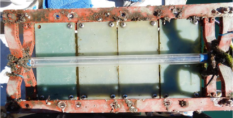
Figure II.1. An aerial view of the housing unit holding the UVC lamp. Panels are
suited on either side of the lamp for testing. Four of the eight panels were removed
in order to view the lamp in the middle for this photograph. ................................... 10
Figure II.2. An aerial view of one of the two LED housing units. One of the LED
strips can be seen, and the second LED strip in the glass sheath is on the opposite
side, treating the two panels seen in the picture. ...................................................... 11
Figure II.3. A representative panel from each treatment group at each visual
assessment timepoint over the course of the experiment. The electrical failure of
LED Strip 4 and subsequent increase in fouling coverage can be observed between
Week 6 and Week 8. ................................................................................................ 14
Figure II.4. Percent coverage by treatment over the course of the field experiment
(mean ± SD). LED panels 7 and 8 from LED Strip 4 were not included in the
average. .................................................................................................................... 16
Figure II.5. Average percent coverage of fouling taxa by treatment over the course
of the field experiment. LED panels 7 and 8 from LED Strip 4 were not included.16
Figure II.6. Percent coverage by treatment group through Week 6 (mean ± SD).
Different letters indicate significant differences between groups. F = 94.12,
p<0.0001. ................................................................................................................. 18
xi
Figure II.7. Percent coverage by treatment group through the duration of the 12
week experiment (mean ± SD). LED panels 7 and 8 were excluded from this
analysis. Different letters indicate significant differences between groups. F =
104.9, p<0.0001. ...................................................................................................... 19
Figure III.1. A close up of the UVC wand (left) and the LED strip (right). ............ 27
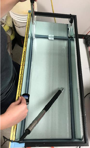
Figure III.2. An overhead view of the turbidity tank experiment at 0 FNU. The
LED strip in the glass sheath is seen at the top left held at the corner of the tank,
while the Solar Light sensor (PMA2180) is moved along the tank edge. The YSI
turbidity sensor is seen at the bottom of the picture for continuous monitoring. The
UVC wand is inactive in the top right of the tank. .................................................. 29
Figure III.3. An overhead view of the turbidity tank experiment at 10 FNU. The
UVC wand is being actively measured by the PMA2122 sensor and the LED in the
glass sheath rests in the upper right corner of the tank. The YSI turbidity sensor is
seen at the bottom of the picture for continuous monitoring. .................................. 30
Figure III.4. Irradiance (in mW/cm
2
) measured over distance (cm) using the UVC
wand. The key indicates different turbidities. .......................................................... 32
Figure III.5. Irradiance (in mW/cm2) measured over distance (cm) from the UVC
LED strip. The key indicates different turbidities. The y-axis is the same scale as
Fig. IV.4 for easier visual comparison of the two sources. ...................................... 32
Figure III.6. Maximum distance of transmission (in cm) of different UVC sources
in a range of turbidities (FNU) (mean ± SD). .......................................................... 34
xii
Figure IV.1. Close up of a pseudobarnacle used to measure adhesion, measuring
2.3 cm in height and 1 cm in base diameter. ............................................................ 41
Figure IV.2. The lamp in its holder inside a tank of fresh water. The 12 slides can
be seen underneath the operating lamp, affixed to a plastic microscope slide holder.
.................................................................................................................................. 44
Figure IV.3. One of the LED tubes in its holder inside a tank of fresh water. Four of
the slides can be seen attached to a plastic microscope slide holder and are treated
by the unseen LED strip on the opposite side of the aluminum heat sink. .............. 44
Figure IV.4. A representative epoxy-coated slide from each treatment group. The
color in the middle of each slide is residual Sharpie from the scratch hardness test.
.................................................................................................................................. 47
Figure IV.5. Thickness of the epoxy slides from each group before and after
treatment, measured in micrometers (mean ± SD). For treatment: F = 0.02, p =
0.999. ........................................................................................................................ 48
Figure IV.6. Hardness number (in Gigapascals) of the epoxy slides by treatment
group (mean ± SD). Different letters indicate significant differences between
groups. F = 5.763, p = 0.00515. ............................................................................... 49
Figure IV.7. A representative fouling release-coated slide from each treatment
group. The color in the middle of each slide is residual Sharpie from the scratch
hardness test. ............................................................................................................ 50
xiii
Figure IV.8. Thickness of the fouling release slides from each group before and
after treatment, measured in micrometers (mean ± SD). For treatment: F = 0.915, p
= 0.481. .................................................................................................................... 51
Figure IV.9. Hardness number (in Gigapascals) by treatment group of the fouling
release-coated slides (mean ± SD). F = 1.659, p = 0.212. ....................................... 52
Figure IV.10. Adhesion test results before and after treatment from the fouling
release-coated slides (mean ± SD). For treatment: F = 0.685, p = 0.613. ................ 54
Figure IV.11. A representative antifouling coating slide from each treatment group.
The darker spot on the control slide is residual Sharpie from the scratch hardness
test. ........................................................................................................................... 55
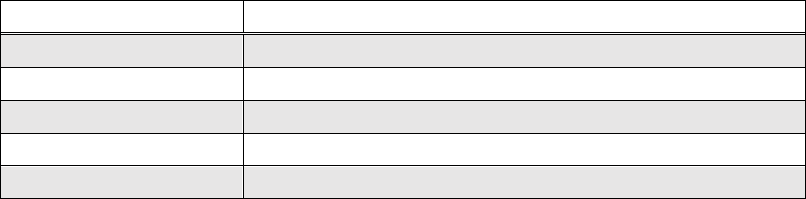
Figure IV.12. Thickness of the antifouling coating slides from each group before
and after treatment, measured in micrometers (mean ± SD). For treatment: F =
0.749, p = 0.574. ...................................................................................................... 56
Figure IV.13. Hardness number (in Gigapascals) by treatment group of the
antifouling coating slides (mean ± SD). Different letters indicate significant
differences between groups. F = 6.12, p = 0.00398. ................................................ 57
Figure IV.14. Close up of the LED strip after 8 weeks of operation with visible
brown condensation inside its glass sheath. ............................................................. 65
1
CHAPTER I
INTRODUCTION
Biofouling, or the unwanted growth of organisms on submerged surfaces, is
a costly nuisance for many marine industries. For the shipping industry, biofouling
compels increased energy costs to overcome biofouling-induced drag, consequently
increasing greenhouse gas emissions (Murthy et al. 2009, Schultz et al. 2011,
Swain and Lund 2016, Qiu et al. 2022). Biofouling also represents a significant
environmental threat, as ships become vectors for the global spread of invasive
species (Bax et al. 2003, Georgiades et al. 2021, Hunsucker et al. 2019a).
Therefore, resources must be devoted to preventative treatments, such as manual
grooming by divers, grooming of the hull by remotely operated vehicles (ROVs),
marine coatings and their upkeep, or a combination of these processes (Swain
2010, Swain 2017, Swain et al. 2022).
Antifouling coatings rely on leaching biocides to prevent biofouling growth,
requiring regular reapplication and consequently limiting the lifespan of the paint
(Lejars et al. 2012). Additionally, the biocides used are often toxic to nontarget
organisms and bioaccumulate in sediment, causing unforeseen ecological
consequences (Evans et al. 2000, Lejars et al. 2012). Such was the case with
tributyltin (TBT), a tin-based biocide, which was linked to the development of male
sex organs in female gastropods and reproductive failure in oyster populations
(Callow and Callow 2002, Evans et al. 2000, Qiu et al. 2022 ). After the ban on
2
TBT in 2008, copper became a very popular biocide for use in antifouling coatings
(Lejars et al. 2012, Swain 2010). However, several fouling species, including the
barnacle Balanus amphitrite, are copper tolerant, decreasing the effectiveness of
copper-based antifouling coatings (Hunsucker et al. 2019a). Fouling release
coatings may be more environmentally friendly by not containing any toxins,
relying instead on chemical properties from silicone or fluorine to prevent strong
adhesion of fouling organisms (Lejars et al. 2012, Kavanagh et al. 2005Swain
1999, Qiu et al. 2022). Yet these coatings are easily damaged, expensive, and rely
on movement through water to properly perform; ships in dock may still require
grooming with brushes in order to maintain a clean surface (Callow and Callow
2002, Kavanagh et al. 2001, Qiu et al. 2022, Tribou and Swain 2010). While the
use of antifouling and fouling release coatings has proved effective overall, they are
not enough by themselves to completely prevent fouling, especially on more niche
areas of a ship, like propeller shafts and seachests (Bixler and Bhushan 2012, Piola
et al. 2016).
A preventative biofouling treatment that has garnered attention in recent
years is the use of UVC (ultraviolet-C) light (Salters and Piola 2017). The
germicidal effects of UVC have been understood for over a century, and UVC has
been used to disinfect air, drinking water, wastewater, surfaces, food, and medical
equipment (Bixler and Bhushan 2012, Carré et al. 2018, Kim et al. 2016, Kowalski
2009). UVC has also been tested successfully as an antifoulant for marine sensors
and reverse osmosis membranes (MacKenzie et al. 2019, Sperle et al. 2020). UVC
3
denotes light from 200 to 280 nm of wavelength, which includes the 260 nm peak
absorption for DNA (Kim et al. 2016). When DNA is subjected to UVC, the double
helix shape is disturbed through the formation of neighboring thymine bonds,
inhibiting cellular functions and leaving the microorganism unable to reproduce
(Kowalski 2009). This antimicrobial property of UVC has been shown to prevent
the formation of biofouling on underwater surfaces (Salters and Piola 2017). The
Center for Corrosion and Biofouling Control (CCBC) at the Florida Institute of
Technology has continued to conduct much of this novel research using a low-
pressure mercury UVC lamp (Braga et al. 2020a, Braga et al. 2020b, Hunsucker et
al. 2019b, Richard et al. 2021).
Experiments with UVC lamps have yielded promising results,
demonstrating that they are effective at preventing biofouling when applied
intermittently at short distances and have greatest success when used in
combination with marine coatings (Braga et al. 2020a, Hunsucker et al. 2019b,
Richard et al. 2021). However, these lamps have a number of drawbacks, such as
fragility, time needed to warm up, and the use of mercury (Kim et al. 2016). UVC
lamps may also cause damage to the surface in which biofouling is unwanted
(Hunsucker et al. 2019b). In addition, these lamps are constricted to emitting light
at 254 nm (Li et al. 2017).
The mercury in UVC lamps is especially problematic as mercury is a
dangerous environmental pollutant and can bioaccumulate in aquatic food webs if a
lamp was to break (Kessler 2013). Through the United Nations Environment
4
Programme, the Minamata Convention of Mercury came into effect in 2017 (EPA
2021). The treaty requires countries to limit environmental mercury emissions
through processes such as eliminating mining mercury, enhanced regulation of
trade, and phasing out mercury in products such as batteries (EPA 2021, Kessler
2013, Kim and Kang 2020, Nguyen et al. 2019). The Minamata Convention of
Mercury does not specifically mention UVC lamps (Nguyen et al. 2019). However,
the implications for the future of global mercury use are clear, and industries are
under pressure to find alternative solutions.
For UVC lighting, an emerging technology could be the solution to these
issues: UVC-emitting LEDs (light-emitting diodes). An LED is a semiconductor
that emits light when a current is applied (Hsu et al. 2021). LEDs do not contain
mercury, can be produced at any specific wavelength, and have lower voltages
(Kooshan et al. 2022, Li et al. 2017). UVC LEDs have already successfully been
utilized for disinfection, as well as biofouling prevention (Salters and Piola 2017,
Shur 2021). Since the early 2000s, numerous companies have developed their own
UV LEDs in a range of wavelengths. However, a limitation to LEDs is that one
diode is a fraction of the size of the UVC lamp, or roughly 100x shorter and 5x
narrower. To combat this, manufacturers are releasing products containing more
than one LED arranged in a module or array, such as 12 diodes in a 16 cm strip.
The market for UVC LEDs is anticipated to reach $2.5 billion by 2025, an
estimate no doubt supported by the Minamata Convention leading to the
obsolescence of lamps and the increased use of UVC LEDs during the COVID-19
5
pandemic (Shur 2021). However, as LEDs replace lamps, few studies have
attempted to compare the light sources’ effects (Kim et al. 2016, Li et al. 2017,
Wood et al. 2020). While both Kim et al. (2016) and Li et al. (2017) found the
LEDs to be more efficacious than the lamp, these studies were limited to the use of
UVC for bacterial inactivation. To date, no study has attempted to compare and
contrast a UVC lamp and UVC LEDs as they relate to biofouling, representing a
dearth of knowledge that necessitates this thesis.
The purpose of this thesis is to conduct a comprehensive and thorough
investigation into the efficacy of UVC LEDs for biofouling control and compare
their effects to a mercury-based UVC lamp. The lamp used was a 25 W low-
pressure mercury lamp that emits UVC light at 254 nm in 360º, sourced from Aqua
Ultraviolet (Figure I.1). The lamp was connected to a transformer, which supplied a
voltage of 120 V and a current of 0.48 A. It measured 37.7 cm long with a diameter
of about 2 cm. In order to adequately compare LEDs to the lamp, a module design
was chosen that contained several LEDs along a length of aluminum nitride,
mimicking the lamp’s proportions in two dimensions. The Klaran light engine (LE-
24V-12V-HC) contained 12 KL265-50V-SM-WD LEDs (measuring 0.35 x 0.35
cm each), which were already integrated into attached circuitry. This was
advantageous because it meant the light engine only had to be connected to a power
supply before it could be operated, allowing for easy laboratory testing and
eliminating any demand for manual soldering of LEDs, which is not recommended
by many manufacturers. The LED strip measured 1.2 x 16 cm (Figure I.1). Each

6
LED emitted UVC light at 260 – 275 nm with a peak at 270 nm and had an
emittance angle of 130º. The strip required 24 V at 1.5 A, resulting in a power
consumption of 29 W. The lower voltage of the LEDs is often cited as an
advantage over lamps, suggesting safer use and the ability to operate on a battery or
photovoltaic cell (Kooshan et al. 2022, Würtele et al. 2011).
Figure I.1. A picture of the UVC lamp (top) and the UVC LED strip (bottom), with a ruler
for scale. Both light sources are housed in glass sheaths for waterproofing.
The research presented in this thesis is arranged in the subsequent three
chapters. The second chapter (Experiment #1) is a field study comparing the
efficacies of the LED strip and the lamp as biofouling preventatives on an uncoated
surface. The field experiment also tests if there is a difference in biofouling
community composition when exposed to 270 nm or 254 nm UVC light. The third
chapter of this thesis (Experiment #2) is a laboratory study assessing the
transmission of different wavelengths of UVC light through water with a range of
turbidities. The fourth chapter (Experiment #3) is a laboratory experiment
evaluating the effects of UVC exposure on marine coatings. In total, the three
7
experiments provide a detailed comparison of a UVC lamp and UVC LEDs and
their efficacy of utilization for biofouling control in the marine environment.
8
CHAPTER II
UVC LAMP VS. UVC LEDS IN PREVENTING BIOFOULING
INTRODUCTION
The efficacy of UVC as a biofouling preventative previously been
demonstrated through the application of both lamps and LEDs. Braga et al. (2020a)
and Hunsucker et al. (2019b) found that continuous operation of the 25W Aqua
Ultraviolet lamp (described in Chapter I) kept epoxy-coated test panels completely
free of biofouling after 2 months of immersion in a marine environment. Further
testing of the lamp at different exposure intervals indicated that 10 minutes of UVC
light per day prevented the formation of all macrofouling (Richard et al. 2021).
Studies utilizing UVC LEDs have yielded similar results. Salters and Piola (2017)
found that LEDs embedded in silicone kept the surface completely clean when
operating continuously. Another study investigating interval testing revealed that as
little as 24 minutes a day of LED exposure can prevent all macrofouling growth on
uncoated glass (MacKenzie et al. 2019). However, none of these studies offer a
comparative analysis of lamps and LEDs. Based on this prior research, an
experiment was undertaken to investigate the effects of equivalent intermittent
doses from a mercury powered lamp compared to LED strips.
9
Hypothesis 1:
Since the LEDs from Klaran emit UVC light containing the peak absorption
wavelength for DNA (260 nm), they will be more effective at preventing the
formation of biofouling on test panels than the lamp (254 nm).
METHODS AND MATERIALS
Four UVC LED light strips, as described in Chapter I, were sourced from
Klaran. Two strips were cemented on opposite sides of an aluminum bar heat sink,
and then each aluminum bar was inserted into its own cylindrical quartz glass
sheath and sealed to be waterproof. A UVC lamp, sourced from Aqua Ultraviolet
(specifications described in Chapter I), was also tested in its biofouling efficacy. A
quartz glass sheath also held the lamp.
The LED strips measured 1.2 x 16 cm, while the lamp measured 2 x 37.7
cm. This meant that one LED strip could only treat two test panels (9.7 x 19.3cm)
due to the LEDs’ narrow emittance angle (~130º) and the strip’s short length, while
the lamp could treat eight panels.
To hold the test panels, three housing units were constructed from
aluminum angles and 3D-printed plastic. They were then coated with epoxy
(International Intergard) followed by a top coat of a copper antifouling paint
(Interspeed BRA640). Each housing unit measured 45.7 x 7.7 x 20 cm and could
hold a possible eight panels, four on opposite sides, with the glass sheath running
down the middle (Figure II.1). The panels sat 2.5 cm away from the light source
10
(Hunsucker et al. 2019b). The test panels were uncoated 9.7 x 0.3 x 19.3 cm
polycarbonate. They were attached to the housing units with screws and nuts for
simple removal during visual assessments.
One housing unit held the UVC lamp and eight panels (Figure II.1). Since
UVC light cannot transmit through opaque materials, the back sides of these eight
panels were analyzed as controls with no UVC exposure (Kowalski 2009). The
other two housing units held the four LED strips and their combined eight test
panels (Figure II.2).
Figure II.1. An aerial view of the housing unit holding the UVC lamp. Panels are suited on
either side of the lamp for testing. Four of the eight panels were removed in order to
view the lamp in the middle for this photograph.

11
Figure II.2. An aerial view of one of the two LED housing units. One of the LED strips can
be seen, and the second LED strip in the glass sheath is on the opposite side, treating
the two panels seen in the picture.
Frequency of exposure for the lamp was chosen as 10 minutes/day, based
on previous biofouling studies demonstrating a short intermittent dose can prevent
all macrofouling (Richard et al. 2021). The lamp and LEDs emit at difference
wavelengths (254 nm vs. 270 nm, respectively) and have different intensities. In
order to calculate an equivalent exposure time from the LED strip, a UVC sensor in
the strip’s wavelength range was purchased from Solar Light (PMA2180). The
light output of the strip was measured from 2.5 cm away at various spots over the
strip in freshwater (the same distance between the LED strip and test panel within
the housing unit). The LED strip’s average intensity measured 0.342 mW/cm
2
. The
lamp’s average intensity (already known from previous CCBC studies) was

12
measured to be 1.478 mW/cm
2
, which when multiplied by a time interval of 10
minutes (=600 seconds) yields a daily dose of 886.8 mJ/cm
2
. Therefore, the time
needed of LED operation for an equivalent dose is 2,593 seconds per day, or
roughly 43.2 minutes.
Published literature and preliminary work with the LED strips revealed that
they generate heat very quickly, thus the need for the attachment to the aluminum
heat sink (Hsu et al. 2021). In order to further protect the quality of the electrical
connections, each strip was operated with a 5 seconds on, 5 seconds off duty cycle.
Additionally, the 2 LED strips in the same glass tube (sharing a heat sink) were
operated sequentially as opposed to concurrently. To accomplish this, a code was
written in the program Arduino and uploaded to an Arduino Nano to properly
control the four LED strips. The lamp was connected to an outdoor programmable
timer (BN-LINK) and set for 10 minutes daily.
The field experiment was deployed on November 8, 2021 and ran until
January 31, 2022, for a total of 12 weeks. The experiment was conducted from the
CCBC test barge (28°24′31.01"N, 80°37′39.54"W). The surrounding water has an
average salinity of 34 ± 2 ppt, an average temperature of 27 ± 2 °C, and high
fouling pressure year round. The housing units were checked weekly for proper
operation, and a visual assessment was conducted every two weeks. For a visual
assessment, all panels were detached, photographed with a Nikon COOLPIX W300
13
digital camera, and reattached. The photographs were then analyzed for percent
growth of fouling organisms according to ASTM Standard D6990-05 (ASTM
International 2005).
Percent coverage between treatment groups was analyzed in R (Version
4.1.1) with a repeated measures ANOVA, in which treatment was the main factor,
panels were treated as experimental units nested in treatment, and there was a
possible treatment*week interaction. Significant main factors were subjected to a
Games-Howell post hoc test (Zar 2010). To determine if the fouling community
composition differed between the UVC-treated groups, a PERMANOVA using a
Bray-Curtis similarity matrix was conducted on panels exhibiting fouling growth
with the R package “vegan”. Graphs were composed in R using the package
“GrapheR”, as well as in Microsoft Excel.
RESULTS
After twelve weeks immersion, both the UVC lamp and UVC LEDs were
able to prevent significant biofouling growth compared to control panels. Around
Week 7, LED Strip 4 suffered an electrical malfunction, leading to a large increase
in fouling on LED test panels 7 and 8 compared to the other LED strips’ panels
(Figure II.3). Because of this, the data were analyzed in two parts. One analysis
included all panels through Week 6, and the second analysis included all panels
except for LED panels 7 and 8 through Week 12.

14
Figure II.3. A representative panel from each treatment group at each visual assessment
timepoint over the course of the experiment. The electrical failure of LED Strip 4
and subsequent increase in fouling coverage can be observed between Week 6 and
Week 8.
Week 2
Week 4
Week 6
Week 8
Week 10
Week 12
15
The control panels reached 100% coverage by Week 4 (Figure II.4).
Initially, the control panels were fouled with biofilm, green algae, calcareous
tubeworms, and tunicates (Figure II.5). By Week 6, there was also the presence of
arborescent and encrusting bryozoans (Figure II.5). The final visual assessment
during Week 12 also found sponges, sea anemone, barnacle, and silt tube-building
amphipods (Figure II.5). While some of the LED panels assessed in Week 12 had
silt buildup, neither of the UVC-treated groups (lamp or LED) experienced any
hard fouling (Figure II.5). The lamp’s panels remained almost completely clean
through Week 12. The growth they did develop was a small amount of green algae
(Figure II.5). The LED strips’ panels remained clean in the middle. The progression
of fouling developing from the edges of the panels can be observed throughout the
weeks in Fig. II. 3 (p. 14). Through Week 10, the growth on the LED panels was
mostly biofilm (Figure II.5). By Week 12, the fouling growth included green algae.

16
Figure II.4. Percent coverage by treatment over the course of the field experiment (mean ±
SD). LED panels 7 and 8 from LED Strip 4 were not included in the average.
Figure II.5. Average percent coverage of fouling taxa by treatment over the course of the
field experiment. LED panels 7 and 8 from LED Strip 4 were not included.
The first RMANOVA was conducted on the percent fouling coverage data
from all panels through Week 6. The data required a fourth root transformation to
meet normality assumptions and a Greenhouse-Geisser epsilon correction (=0.893)

17
in order to pass Mauchly’s sphericity test. The results showed the treatment groups
had significantly different coverages (p<0.0001) (Table II.1, Figure II.6). While
panel was significant (p<0.0001), this variable corresponds to experimental unit
and was not interpreted further. Week was also found to be significant (p=0.0003),
but a post diagnostic test could not detect a statistically significant difference
between them (Table II.1). The treatment*week interaction was also significant
(p=0.0458) (Table II.1). This signifies that the effect of treatment was not
equivalent across the 12 weeks of the experiment. However, the interaction was not
relevant to the research question and was simple and orderly, so was not interpreted
further.
Table II.1. RMANOVA results from the field experiment through Week 6. The df[GG]
column represents the new degrees of freedom after the Greenhouse-Geisser epsilon
correction (=0.893) is applied.
df
df[GG]
SS
MS
F
p
Treatment
2
2
106.31
53.15
94.12
<0.0001
Week
2
1.79
3.30
1.84
13.17
0.0003
Panel
21
21
11.86
0.56
4.123
<0.0001
Treatment*Week
4
3.58
1.38
0.39
2.75
0.0458
Error
42
42
5.75
0.14
Total
71
70.37
128.60

18
Figure II.6. Percent coverage by treatment group through Week 6 (mean ± SD). Different
letters indicate significant differences between groups. F = 94.12, p<0.0001.
The second RMANOVA was performed on the percent fouling coverage of
all panels throughout Week 12, excluding LED panels 7 and 8. This data also
required a fourth root transformation and a Greenhouse-Geisser epsilon correction
(=0.353). The treatments were still statistically different (p<0.0001), as was panel
(p<0.0001), week (p<0.0001), and treatment*week (p=0.01) (Table II.2, Figure
II.7). The experimental unit was not interpreted further, and the post diagnostic test
could not reveal a significant difference between weeks. The interaction was also
found to still be simple and orderly.

19
Table II.2. RMANOVA results from the field experiment through Week 12. The df[GG]
column represents the new degrees of freedom after the Greenhouse-Geisser epsilon
correction (=0.353) is applied. LED panels 7 and 8 from LED Strip 4 were excluded
from this analysis.
df
df[GG]
SS
MS
F
p
Treatment
2
2
193.75
96.88
104.9
<0.0001
Week
5
1.76
11.64
6.61
60.13
<0.0001
Panel
19
19
17.54
0.92
8.36
<0.0001
Treatment*Week
10
3.53
4.77
1.35
12.27
0.0100
Error
95
95
10.85
0.11
Total
131
121.29
238.55
Figure II.7. Percent coverage by treatment group through the duration of the 12 week
experiment (mean ± SD). LED panels 7 and 8 were excluded from this analysis.
Different letters indicate significant differences between groups. F = 104.9,
p<0.0001.
Community composition comparisons were also applied to the data in two
parts. The first PERMANOVA included the 1 UVC panel (out of a possible 8) and
6 LED panels (out of 8) that had fouling growth at Week 6. The two treatments’

20
fouling communities were not different (p=0.145) (Table II.3). The second
PERMANOVA included all 8 UVC panels and 6 LED panels that exhibited fouling
during Week 12, excluding LED panels 7 and 8. The UVC-treated fouling
communities during Week 12 were not different (p=0.148, Table II.4).
Table II.3. PERMANOVA results comparing the community composition on the 1 UVC
panel and 6 LED panels that exhibited fouling during Week 6.
df
SS
MS
F
R
2
p
Treatment
1
0.64442
0.64442
17.556
0.77833
0.145
Error
5
0.18353
0.03671
0.22167
Total
6
0.82795
1.00000
Table II.4. PERMANOVA results comparing the community composition on the 8 UVC
panels and 6 LED panels that exhibited fouling during Week 12. LED panels 7 and
8 from LED Strip 4 were excluded from analysis.
df
SS
MS
F
R
2
p
Treatment
1
0.5106
0.51062
2.062
0.14664
0.148
Error
12
2.9716
0.24763
0.85336
Total
13
3.4822
1.00000
DISCUSSION
The LED panels (excluding the two which were removed from analysis - 7
and 8) never exceeded a maximum percent coverage average of 7.5%, which
consisted of light biofilm and green algae. However, this was still found to be
statistically significantly different from the UVC lamp treated panels. As seen in
the photographs from Figure II.3 (p. 14), fouling growth observed on the LED
panels began near the screw holes and developed along the panel edges while the
21
middle of the panels remained clean. The rectangular test panels used in this
experiment were 9.6 cm longer than their width. Previous studies utilizing UVC
LEDs as a biofouling preventative have demonstrated their success when treating
small circular surfaces (MacKenzie et al. 2019, Salters and Piola 2017).
Additionally, if there is a small shadow effect preventing UVC application,
substantial fouling growth can occur (Ryan et al. 2020). It is likely that the screws
provided a shadow effect, allowing biofilm development. The biofilm then spread
along the panel edges which received a lower dose of UVC than the middle of the
panel. Fouling growth beginning on the edges of panels and spreading towards the
middle has also been observed on UVC lamp treated panels in other experiments,
suggesting the additional influence of an underlying biological pattern (Hunsucker
et al. 2019b).
The UVC-treated panels only exhibited growth of biofilm and green algae.
This suggests a higher tolerance to UVC than organisms only found on the control
panels, such as calcareous organisms (tubeworm, barnacle, and encrusting
bryozoans), which is in agreement with results from other UVC biofouling studies
(Hunsucker et al. 2019b, MacKenzie et al. 2019). Biofilms, a matrix containing a
compilation of bacterial populations, are especially resistant to damage from UVC
light because the biofilm with its extracellular secretions acts as a physical barrier
protecting the bacteria (Gora et al. 2019, Elasri and Miller 1999). This property can
help explain how biofilm could grow on parts of the LED panels that were not
subjected to the full UVC dose. Biofilms also experience a greater resistance to
22
UVC with age, indicating that once the biofilm community has settled, it will be
more difficult to halt biofouling progression (Naik et al. 2022). Nonetheless, the
LEDs were able to prevent recruitment of higher fouling organisms, suggesting that
the lower dose of UVC changed may have altered that aspect of the biofilm (Hung
et al. 2005). The observation of minimal fouling on the UVC treated panels was to
be expected from this experimental setup, as even continuous UVC application has
been shown to experience breakthrough biofilm growth (Torkzadeh and Cates
2021).
The results from the two PERMANOVAs indicated that even though the
two UVC treatments varied by specific wavelength, their fouling community
composition was not statistically different. Since the visual assessments could only
be completed accurately to the familial level, it is possible that genetic or
microscopic research could find a difference. Both multispecies and monospecies
biofilms’ abilities to attract larval settlement is reduced by UVC exposure (Hung et
al 2005); it is not possible to tell from this data if 254 nm UVC leads to a different
biofilm composition than 270 nm, and this could be teased out during future
studies.
While the exact reason why LED Strip 4 failed is unknown, it was observed
to have issues prior to Week 7. The glass sheath holding LED Strips 3 and 4 in one
of the housing units developed noticeable condensation inside, requiring its
disassembling, cleaning, and reassemble on Week 3. It is possible that even though
both LED tubes were waterproofed in the same way that the tube containing LED
23
Strip 4 was not completely sealed. It is also possible that the soldered electrical
connections came unattached due to physical movement from storms or wave
action, or the connections failed because of excess heat.
The small differences observed between the lamp and LED may also be a
factor of using a single dose of UVC versus a pulsed or intermittent exposure,
which would repeatedly disturb the surface. More frequent disturbances to a
community can lead to cumulative damage and less resiliency than observed with a
one-off event (Carnell and Keough 2020). This additive effect of frequency could
have enhanced the performance of the lower powered LED strips, although the less
frequent, more severe disturbance from the lamp prevented more fouling.
These results show the effects of short, intermittent UVC doses to be
effective at preventing most biofouling formation in a high pressure fouling
environment. Future research could improve upon this data by allowing the
experiment to run for a longer time period or increase the dose of the LED strips so
that the edge of the rectangular panels is subjected to an equivalent dose as the
center of the lamp’s panels. Additionally, the interaction of the two UVC sources
with antifouling coatings should be tested in the field. As demonstrated in this
chapter and Richard et al. (2021), 10 min/day of exposure from the UVC lamp is
powerful enough to prevent most biofouling formation on an inert surface. When
combined with a fouling release or biocidal antifouling coating, doses as low as 1
min/day can produce similar results (Hunsucker et al. 2019b). Comparable
24
experimental setups could be used to examine the predicted synergistic effect of
UVC LEDs with antifouling coatings.
25
CHAPTER III
EFFECT OF TURBIDITY ON UVC TRANSMISSION
INTRODUCTION
The practical application of UVC as a biofouling preventative in a marine
environment requires understanding the effects of environmental variables on its
transmission. One such variable is turbidity, a measurement of how much light is
scattered by particles in the water (Anderson 2005). Turbidity is caused by
suspended and dissolved materials, such as clay, silt, dyes, and plankton, and can
be qualitatively observed by the cloudiness and color of the water (Anderson 2005,
ASTM International 2003, Davies-Colley and Smith 2001). Turbidity is calculated
by measuring the angle that a beam of light emitted from a sensor is scattered
(Anderson 2005). Depending on the wavelength of light used, this measurement is
reported in NTU (Nephelometric Turbidity Unit) or FNU (Formazin Nephelometric
Unit), which are considered relatively equivalent.
Previous research conducted by CCBC has demonstrated a clear negative
relationship between turbidity and UVC transmission (Florida Tech, unpublished
data). This was accomplished by measuring the transmission from a mercury-based
UVC light source over distance in a range of turbidities. The UVC light source
utilized in the aforementioned experiment was a sterilization wand (Coospider).
The wand was used because its smaller size (2 x 21.5 cm) meant easier
maneuvering in a glass tank compared to the longer Aqua Ultraviolet brand lamp
26
(described in Chapter I). Both the wand and the lamp emitted light at 254 nm and
had no significant difference in freshwater transmission (p=0.556) (Florida Tech,
unpublished data). The wand had a manufacturer specified voltage of 110 V and
power of 7 W, similar to the lamp’s 120 V.
While this research is useful in attempting to explain turbidity and UVC, it
did not test UVC LEDs. The purpose of the following experiment is to replicate the
results obtained from previous CCBC work while comparing them to the
transmission of UVC LEDs in different turbidities.
Hypothesis 2:
Given that the LEDs emit light at 270 nm, it is hypothesized that they will
transmit further in water than the shorter 254 nm wavelength from the wand.
METHODS AND MATERIALS
The setup for the experiment was replicated from the previously described
CCBC research, so the Coospider UVC wand was used instead of the Aqua
Ultraviolet UVC lamp employed in Chapters II and IV. A 12 UVC LED light
engine from Klaran (270 nm) was tested alongside the UVC wand in order to
compare the transmissions of the two different UVC light sources in various
turbidities (Figure III.1).

27
Figure III.1. A close up of the UVC wand (left) and the LED strip (right).
A glass tank (77 x 32 x 32.5 cm, 75 L) was filled with tap water and
measured with a ProSwap digital water quality meter with attached ProDSS
turbidity sensor (Yellow Springs Instruments) to ensure the turbidity was 0 FNU.
Two Solar Light digital sensors were used throughout the experiment. One sensor
measured at 254 nm for the wand (PMA2122) and the second at 270 nm for the
LED strip (PMA2180). Both attached to the same radiometer (PMA2100, Solar
Light) which provided the irradiance readout as mW/cm
2
(wand) or µW/cm
2
(LED
strip).
A piece of measuring tape was attached to the edge of the tank with tape to
easily measure distance. The wand was held in the corner of the tank and turned on.
The PMA2122 sensor was connected to the radiometer and held at 1 in (2.5 cm)
28
away from the wand. The sensor was suspended in the water by hand at the point
where the chassis was completely submerged (about 5 cm). Irradiance was
measured every inch along the tape measure until no more light could be detected
and the radiometer read 0.000 mW/cm
2
. The spot where the radiometer could no
longer sense the UVC was considered the maximum distance of transmission for
the UVC source. Then the process was repeated two more times for a total of three
trials. Once complete, the wand was turned off and the LED strip was placed in the
corner. The LED strip was repurposed from the field experiment (Chapter II); it
was already attached to an aluminum heat sink and secured inside a quartz glass
sheath. The operating code in the Arduino Nano was rewritten so that only the LED
strip facing the sensor was receiving power and the LED strip on the opposite side
of the heat sink remained off. The LED strip being measured ran on a 30 second
duty cycle to prevent overheating. The same measuring process mentioned above
for the wand was then repeated. The PMA2180 sensor was attached to the
radiometer and held 1 in (2.5 cm) away from the LED strip. The sensor was moved
1 in at a time down the length of the tank until the radiometer read 0.0 µW/cm
2
.
This process was repeated two more times with the LED strip (Figure III.2).
29
Figure III.2. An overhead view of the turbidity tank experiment at 0 FNU. The LED strip in
the glass sheath is seen at the top left held at the corner of the tank, while the Solar
Light sensor (PMA2180) is moved along the tank edge. The YSI turbidity sensor is
seen at the bottom of the picture for continuous monitoring. The UVC wand is
inactive in the top right of the tank.
In order to determine how measurements will change with increased
turbidity, sediment was collected from the Florida Tech Anchorage on February 23,
2022 (28°04'36.9"N 80°36'01.8"W). The Anchorage is located where the mouth of
Crane Creek meets the Indian River Lagoon. It was collected from the shallow (<1
m), nearshore water and transported in a small cooler to a laboratory setting on the
Florida Tech main campus, where it was used in the turbidity tank experiment the
same day. The sediment had a consistency of muddy sand.

30
Sediment from Anchorage was added to the tank to raise the turbidity to 10
FNU. The tank water was agitated with a paint stirrer attached to an electric drill to
achieve uniform suspension. Once the YSI turbidity sensor measured 10 FNU at 5
cm deep, the transmission of the wand was measured according to the steps
outlined above, followed by the LED strip (Figure III.3). Because the LED strip’s
testing took several minutes due to the duty cycle, the tank was intermittently
stirred to maintain proper turbidity readings at the top of the tank. More sediment
was added to the tank to reach a turbidity of 20 FNU, then the two UVC sources’
transmission was measured again. This process was repeated at 30 FNU, 40 FNU,
and 50 FNU, with 3 trials for each source at each turbidity.
Figure III.3. An overhead view of the turbidity tank experiment at 10 FNU. The UVC wand
is being actively measured by the PMA2122 sensor and the LED in the glass sheath
rests in the upper right corner of the tank. The YSI turbidity sensor is seen at the
bottom of the picture for continuous monitoring.
31
The data was analyzed in R (Version 4.1.1) using a two-way factorial
ANOVA, where the main factors were UVC source and turbidity with an
interaction of UVC source*turbidity. Any significant factors were subjected to a
Tukey post-hoc test in R. The irradiance measurements for the LED strip were
converted to mW/cm
2
so the two sources could be compared evenly. The data also
had to be transformed by a fourth root in order to meet the assumptions for
ANOVA. Graphs were constructed in R using the package “GrapheR” and also in
Microsoft Excel.
RESULTS
In clear water, the UVC wand had a maximum recorded irradiance of 0.915
mW/cm
2
, while the LED strip’s maximum was 0.219 mW/cm
2
(Figure III.4, Figure
III.5). At the highest tested turbidity (50 FNU), this measurement was significantly
reduced for both sources. The wand’s maximum irradiance fell to 0.142 mW/cm
2
,
and the LED strip’s was 0.098 mW/cm
2
(Figure III.4, Figure III.5). All maximum
irradiance values were obtained from 2.54 cm away from the light source and
declined with distance.

32
Figure III.4. Irradiance (in mW/cm
2
) measured over distance (cm) using the UVC wand. The
key indicates different turbidities.
Figure III.5. Irradiance (in mW/cm2) measured over distance (cm) from the UVC LED strip.
The key indicates different turbidities. The y-axis is the same scale as Fig. IV.4 for
easier visual comparison of the two sources.

33
When comparing maximum distance of transmission, the two UVC sources
were significantly different from each other (p<0.0001) (Table III.1, Figure III.6).
The UVC wand outperformed the LED strip in each of the tested turbidities (Figure
III.6). It was able to be detected about 3.39 cm further than the LED strip at a
turbidity of 30 FNU, which was the largest difference between the two sources’
maximum distances. The smallest difference was 0.85 cm at a turbidity of 20 FNU.
All UVC transmission values were statistically different for each tested turbidity
(p<0.0001) (Table III.1). There was not a significant effect from the interaction of
source and turbidity (p=0.076) (Table III.1).
Table III.1. Factorial ANOVA results from the turbidity tank experiment.
df
SS
MS
F
p
UVC Source
1
0.086
0.0856
36.840
<0.0001
Turbidity
5
7.093
1.4186
610.832
<0.0001
UVC*Turbidity
5
0.027
0.0054
2.306
0.076
Residuals
24
0.056
0.0023
Total
35
7.262

34
Figure III.6. Maximum distance of transmission (in cm) of different UVC sources in a range
of turbidities (FNU) (mean ± SD).
DISCUSSION
The effect of turbidity on the efficiency of UVC as a disinfectant has been
mentioned in several studies, specifically suggesting how larger suspended
particles can act as a shield for smaller organisms (Carré et al. 2018, Gregg et al.
2009, Lewis and Whitby 1995, Rajagopal et al. 2012, Sassi et al. 2005). Additional
research has outlined the response of bacteria to various UVC doses in increasing
turbidities (Adhikari et al. 2020, Gullian et al. 2012). However, most, if not all, of
this work is focused on the relationship of turbidity and UVC for the disinfection of
water samples; not much can be found on measured maximum transmissions of
UVC light. Even less information is available specifically regarding UVC LEDs,
probably due to their more recent development.
35
The hypothesis that the longer wavelength of 270 nm from the LED strip
would transmit further in water than the lamp’s shorter 254 nm was incorrect. It is
possible that the difference in transmission could be related to the different
electrical powers of the two sources. The wand has a power source with a voltage
of 110 V while the LED strip operates on 24 V. The difference could also be a
factor of the 130º vs. 360º emittance angles.
The statistically significant difference between all levels of turbidity was
expected, as they were each separated by 10 FNU and the water became noticeably
murkier over time (personal observation). This is explained by each level requiring
more particles that either acted to scatter light (suspended sediment, clay, or silt) or
decrease clarity (dissolved humus, organic dyes, algae) (Anderson 2005). The
levels tested also have environmental relevance. From May 2020 to November of
2021, the surface water at Anchorage had a mean turbidity of 2.78 ± 1.26 FNU
(range: 1.29 – 7.40) (Florida Tech, unpublished data). When measured at Port
Canaveral, Florida, the mean was 1.30 ± 1.23 FNU with a range of 0.09 – 7.68
(Florida Tech, unpublished data). These types of sites are expected to, and
demonstrably do, experience a turbidity range of 1 – 10 NTU, supplying context for
the 0 and 10 FNU turbidity levels (CWT 2004). Water in the San Francisco Bay
has been recorded ranging from 12 – 54 NTU which also encompasses the
turbidities tested (Klein and Jenkins 1981). Further from land, turbidity is
calculated using color satellites and diffuse attenuation coefficients at a specific
wavelength (K
d
). Clear water, represented by a K
d
(490) of less than 0.1 m
-1
, is
36
roughly 95.67% of the open ocean and varies mostly because of plankton blooms,
which themselves yield a turbidity of ~50 NTU (Shi and Wang 2010, Clear Water
Team 2004). The results presented within could be applied to such bodies of water,
providing an estimation of how UVC transmission will be affected given the
relative turbidity.
Hess-Erga et al. (2008) demonstrated the effects of UVC dose on the rotifer
Brachionus. When the rotifers were associated with particles, they required a
sixfold increase in UVC dose to achieve 99.9% inactivation as compared to free-
living Brachionus, supporting the shadow effect of particles in UVC efficiency
(Hess-Erga et al. 2008). A second experiment demonstrated that the addition of
abiotic or biotic particles (resulting in an unspecified turbidity) led to the reduced
performance of UVC on free-living bacteria. The researchers did not find a major
difference in the protection provided by either particle type on the bacteria (Hess-
Erga et al. 2008). Baldasso et al. (2021) further defined the effects of particles
when treating the MS2 bacteriophage with UVC in water. Humic acids,
representative of organic matter, absorbed UVC, which had a substantial effect on
the inactivation rate constant and thus bacteriophage inactivation (Baldasso et al.
2021). In contrast, kaolinite particles (a clay mineral) could not absorb UVC and
influenced transmission only by scattering, which had an insignificant effect on the
inactivation rate constant (Baldasso et al. 2021).
The composition of the experimental sediment sample can be approximated
from literature. Using data from samples where Crane Creek meets the Indian River
37
Lagoon, the sample likely contained an estimated 39 ± 15% silt and clay and 3.2 ±
1.5% total organic carbon (Fuller et al. 2021). It would be unwise to extrapolate a
conclusion about UVC transmission specific to organic matter content from this
experiment’s limited data, but it does raise several questions. Clay, silt, humic
acids, and dissolved organic matter (estimated by organic carbon) all contribute to
measured turbidity. However, if the partial percent of organic matter in a given
body of water can be determined, then a more accurate dose of UVC can be
calculated, eliminating both under and overapplication of UVC. This could
especially be useful when considering the disinfection of temporary water bodies,
like ballast water. Additionally, this process could be applied to smaller, stagnant
equipment that needs UVC treatment for the prevention of biofouling, like marine
sensors.
38
CHAPTER IV
IMPACTS OF UVC TO MARINE SURFACES
INTRODUCTION
Marine coatings are often used to prevent biofouling, thus preventing drag
on ship hulls (Swain 1998). This is accomplished by promoting weak adhesion of
organisms, such as fouling release coatings, or through leaching of a biocide, like
antifouling paints (Hunsucker et al. 2019b, Lejars et al. 2012, Swain 2010).
However, marine coatings have their disadvantages, such as decreased performance
on niche areas of a ship and limited lifespans (Lejars et al. 2012, Piola et al. 2016).
It has been suggested that the use of UVC light could work synergistically with
marine coatings in order to enhance their performance (Hunsucker et al. 2019b).
While the research by Hunsucker et al. (2019b) did support this conclusion, it was
conducted using only a lamp and did not investigate UVC LEDs. Additionally, the
UVC caused physical damage to the copper antifouling coating when applied
continuously (Hunsucker et al. 2019b). Because the results of this study established
a synergistic effect of UVC on marine coatings, the chemical and physical
interactions that led to the coating’s degradation need to be understood. This
experiment attempts to quantify the impacts of UVC on marine coatings by
exposing several coatings to various doses of light from both a lamp and LEDs.

39
Hypothesis 3:
Since the UVC doses will be equivalent, it is hypothesized that the lamp
and LEDs will provide the same amount of degradation to marine coatings.
METHODS AND MATERIALS
SLIDE PREPARATION
Three test coatings were applied to sheets of 12 x 24 x 1/16” PVC (sourced
from McMaster Carr). The sheets were roughened on one side using a sander for
better adhesion of the coatings and then cut into four equal sections, where each
section of PVC could provide 24 surfaces equivalent to microscope slides. (Note –
due to supply chain issues as a result of the COVID-19 pandemic, glass microscope
slides were backordered and not able to be used in this experiment as planned).
The test coatings used were an epoxy barrier coat (International Intergard
264), a fluoropolymer fouling release paint (Intersleek 1100SR), and a copper-free
antifouling coating which contains 6% ECONEA and 4.8% Zinc Pyrithione (Pettit
ECO HRT). All coatings were applied according to manufacturer standards using a
drawdown applicator with adjustable micrometers (Gardco). Once dry, the PVC
was cut down into 2.5 x 7.5 cm “slides”. The antifouling coating slides were placed
in a container of tap water and left to soak for 7 days. These slides were then
removed and allowed to dry for 5 days.

40
Once all slides were dry, initial thickness measurements were obtained
using a 0-1” manual micrometer (Mitutoyo). This data was converted in
micrometers using the following equation:
Initial adhesion measurements were also gathered from the fouling release
slides. This was accomplished by using pseudobarnacles, which are small metal
studs (Figure IV.1). Three pseudobarnacles were attached to each slide using an
epoxy structural adhesive (Loctite EA E-05CL). They were left to dry for 24 hours
and then pushed off using a force gauge (Imada push-pull scale, 10x.1lbs), similar
to field tests which determine how much force is necessary to remove a barnacle
from a test surface (ASTM Standard D5618-20 2020). The force was recorded in
pounds. The surface area of epoxy on each pseudobarnacle was then scanned into a
computer and calculated using GIMP image editor (Version 2.10.30) and ImageJ
(1.53k, National Institutes of Health). The adhesion strength (pounds per unit area)
was converted into megapascals (MPa).

41
Figure IV.1. Close up of a pseudobarnacle used to measure adhesion, measuring 2.3 cm in
height and 1 cm in base diameter.
The 20 slides of each coating were distributed four to a group (with a total
of five groups). They were distributed so that the average coating thickness for each
group was the same as the overall average of the 20 total slides. This yielded five
groups, each with 12 total slides. The groups were then randomly assigned to
treatment (outlined below).
TANK PREPARATION
In order to test the effects of different UVC sources on different coatings,
the five treatment groups were defined as continuous lamp, 10 min/day of the lamp,
continuous LED, 43.2 min/day LED, and a control group (no UVC exposure)
(Table IV.1). This was based on the same assumption utilized in the field
experiment (Chapter II) that the calculated 43.2 minutes of exposure from the LED
strip is equivalent to 10 minutes from the lamp.
42
Table IV.1. UVC treatment groups with equivalent exposure time.
Group Number
Treatment
1
Continuous lamp for 2 weeks
2
10 min/day lamp (=140min)
3
43.2 min/day LED (~40.3hr)
4
Control (no UVC exposure)
5
Continuous LED totaling 2 weeks
Four LED strips were sourced from Klaran for this experiment, and they
were wired in the same manner as the field experiment (Chapter II). Two strips
were cemented to an aluminum heat sink in a glass sheath so that they emitted light
in opposite directions. Because of the LED strip’s small surface area (1.2 cm x 16
cm), it was concluded that each strip should only treat four slides. Therefore, the
continuous LED group used three of the four strips. Because two of the
aforementioned strips shared a glass sheath, they had to be operated on a duty cycle
to prevent overheating, where one strip was on for 5 seconds, then 5 seconds of
rest, then the second strip on for 5 seconds, then 5 seconds of rest. This meant that
the completion of treatment for the continuous LED group would take four times as
long as the continuous UVC lamp group. Therefore, the continuous lamp and
control groups were scheduled to end after two weeks and the continuous LED
group after 8 weeks (Table IV.1).
In order to conduct the experiment, frames of aluminum angles and 3D-
printed plastic were constructed to hold the glass sheaths in place. Unlike the field
experiment, they were not painted with any antifouling coating due to their use in a
laboratory setting. Three glass tanks (77 x 32 x 32.5 cm, 75 L) were sourced from
43
Aqueon. One tank held the Aqua Ultraviolet UVC lamp and its holder (Figure IV.2.
The lamp in its holder inside a tank of fresh water. The 12 slides can be seen
underneath the operating lamp, affixed to a plastic microscope slide holder.). The
other two tanks each held a glass sheath with 2 LED strips in their respective
frames. The tanks were filled with tap water until the frames were completely
immersed. Each tank also had a digital underwater thermometer to observe
temperature changes. For the control group, a clean bucket was filled with tap
water and given a thermometer. Complete water changes were conducted biweekly.
To keep the slides in one place during immersion, plastic microscope slide
holders (17 x 34 cm) were sourced from Fisher Scientific. Each plastic holder had
spots for 20 possible slides. For Groups 1, 2, and 4, all of the slides from each
group were glued to the middle 12 spots randomly using an epoxy structural
adhesive (Loctite EA E-05CL) (Figure IV.2). For Groups 3 and 5, only four slides
from each group were glued to each plastic holder due to the LED strip’s limited
emittance (Figure IV.3). Once all the glue was cured, the plastic holders were
secured to each frame with zip ties at the start of their treatment. After treatment
was complete, the plastic holder was removed, the slides detached, and then left to
dry for at least 72 hours before data collection.

44
Figure IV.2. The lamp in its holder inside a tank of fresh water. The 12 slides can be seen
underneath the operating lamp, affixed to a plastic microscope slide holder.
Figure IV.3. One of the LED tubes in its holder inside a tank of fresh water. Four of the slides
can be seen attached to a plastic microscope slide holder and are treated by the
unseen LED strip on the opposite side of the aluminum heat sink.

45
Post treatment data collection consisted of thickness measurements using
the micrometer, pseudobarnacle adhesion measurements (only for the fouling
release coated slides), hardness scratch testing, and qualitative comparative
pictures. The hardness scratch test, a measure of coating damage resistance, was
completed according to ASTM Standard G171-03 (2017). A stylus point was
dragged across each slide with a known constant exerted pressure from an attached
weight. The spot where the stylus was dragged was colored in with a Sharpie in
order to more clearly differentiate the edges of the produced scratch from the
surrounding coating. The slide was placed under a Nikon SMZ1270
stereomicroscope with a ruled microscope slide laid on top for scale (NeoSCI). A
picture was taken with the Nikon DS-Ri2 digital camera in the NIS-Elements F
computer program (Version 4.30.01). Then the picture was opened in ImageJ. For
each slide, the scale was determined, and the width of the scratch was measured in
three places. The width measurement (in micrometers) was entered into the
following equation to yield the scratch hardness number in gigapascals:
where P is the pressure exerted on the stylus point in Newtons (known as 5N) and
w is the width of the scratch.
Pictures for qualitative analysis were taken with a Nikon COOLPIX W300
camera. The thickness and adhesion data were each analyzed as a repeated
measures ANOVA in R (Version 4.1.1), where treatment and time were main

46
factors, slides were used as an experimental unit, and there was a possible
treatment*time interaction. If treatment was found to be significant, the main
factors were subjected to a Games-Howell post hoc test (Zar 2010). The scratch
hardness tests results were analyzed by a nested ANOVA in R, with treatment as
the main factor and slides as the experimental unit. Significant main factors were
subjected to a Tukey HSD post hoc test. Graphs were constructed in R using the
package “GrapheR”.
RESULTS
EPOXY
Compared to the control group, the 43.2min/day LED and 10min/day lamp
groups’ epoxy slides developed a darker and slightly yellow shade after treatment
(Fig. III.4). The continuous LED and continuous lamp groups’ slides did not darken
as much but still turned slightly yellow; after these slides completely dried, the
epoxy coating turned chalky and came off when brushed with a finger (Figure IV.4,
personal observation).

47
Figure IV.4. A representative epoxy-coated slide from each treatment group. The color in the
middle of each slide is residual Sharpie from the scratch hardness test.
The average preliminary thickness for each treatment group’s epoxy slides
was 1924.90 ± 1.74 µm (range of group averages: 1921.93 – 1926.17). After
treatment, the average thickness measured 1928.28 ± 9.44 µm (range of group
averages: 1918.76 – 1943.10). The thickness measurements for epoxy slides were
not significant based on treatment (p=0.999), time (p=0.2406), or their interaction
(p=0.1286) (Table IV.2, Figure IV.5). The significance of slide (p<0.0001) was not
interpreted further as experimental unit in favor of analyzing the main factors
(Table IV.2).

48
Table IV.2. RMANOVA results from testing the epoxy slides’ thickness measurements.
df
SS
MS
F
p
Treatment
4
822
205
0.02
0.999
Time
1
115
115
1.493
0.2406
Slide
15
155429
10362
134.964
<0.0001
Treatment*Time
4
651
163
2.121
0.1286
Error
15
1152
77
Total
39
158169
Figure IV.5. Thickness of the epoxy slides from each group before and after treatment,
measured in micrometers (mean ± SD). For treatment: F = 0.02, p = 0.999.
The hardness of the epoxy slides differed significantly by treatment group
(p=0.00515) (Table IV.3). Treatment was again the main factor and the
significance of the slides as experimental units (p=0.00131) was not interpreted
further (Table IV.3). The control group was similar to the continuous LED,
10min/day lamp, and continuous lamp groups’ hardness measurements but
statistically different from the 43.2min/day LED (Figure IV.6). Both of the

49
continuous UVC treatment groups had similar hardness results to each other, as did
both of the intermittent UVC groups (Figure IV.6).
Table IV.3. ANOVA results from the epoxy slides’ scratch hardness test.
df
SS
MS
F
p
Treatment
4
0.005454
0.0013635
5.763
0.00515
Slide
15
0.003549
0.0002366
3.294
0.00131
Error
40
0.0002873
0.0000718
Total
59
0.0092903
Figure IV.6. Hardness number (in Gigapascals) of the epoxy slides by treatment group
(mean ± SD). Different letters indicate significant differences between groups. F =
5.763, p = 0.00515.
FOULING RELEASE COATING
The Intersleek 1100SR fouling release coating produced a shiny, rubbery
finish when first coated, which was still observed after treatment in the control,
43.2min/day LED, continuous LED, and 10min/day lamp groups (Figure IV.7).

50
The continuous lamp group’s fouling release slides developed a lighter colored,
more matte finish that felt softer to the touch (personal observation).
Figure IV.7. A representative fouling release-coated slide from each treatment group. The
color in the middle of each slide is residual Sharpie from the scratch hardness test.
The fouling release groups had an initial thickness measurement of 2236.89
± 59.82 µm (range of group averages: 2160.06 – 2303.99). After treatment, the
thickness was measured at an average of 2231.18 ± 54.02 µm (range of group
averages: 2175.93 – 2293.41). The greater range of the initial coating thickness
compared to the epoxy and antifouling coating slides was because the preliminary
adhesion measurements were used to create the five fouling release treatment
groups. The RMANOVA performed on the fouling release slides’ thickness
measurements revealed no statistical difference based on treatment group (p=0.481)
or time (p=0.0864) (Table IV.4, Figure IV.8). The experimental units’ (the slides)
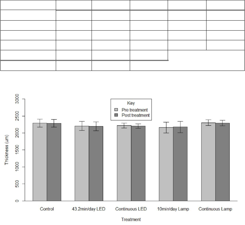
51
significance was not interpreted further in favor of analyzing the main variables
(p<0.0001) (Table IV.4). While the interaction of treatment and time was
significant (p=0.0323), the interaction itself was simple and orderly and warranted
no further analysis (Table IV.4).
Table IV.4. RMANOVA results from testing the fouling release coating’s thickness
measurements.
df
SS
MS
F
p
Treatment
4
102578
25645
0.915
0.481
Time
1
326
326
3.367
0.0864
Slide
15
420440
28029
289.196
<0.0001
Treatment*Time
4
1365
341
3.521
0.0323
Error
15
1454
97
Total
39
526163
Figure IV.8. Thickness of the fouling release slides from each group before and after
treatment, measured in micrometers (mean ± SD). For treatment: F = 0.915, p =
0.481.

52
Treatment did not significantly affect the hardness of the fouling release
slides (p=0.212) (Table IV.5). The experimental unit was significant (p<0.0001)
although this is not important to the analysis (Table IV.5). The mean hardness of
the slides was measured at 0.011 GPa across all treatment groups (Figure IV.9).
The standard deviation was greatest in the intermittent UVC groups (Figure IV.9).
Table IV.5. ANOVA results from the fouling release slides’ scratch hardness test.
df
SS
MS
F
p
Treatment
4
0.0002592
6.480E-05
1.659
0.212
Slide
15
0.0005858
3.906E-05
33.20
<0.0001
Error
40
0.0000471
1.180E-06
Total
59
0.0008921
Figure IV.9. Hardness number (in Gigapascals) by treatment group of the fouling release-
coated slides (mean ± SD). F = 1.659, p = 0.212.

53
As stated previously, the initial adhesion results were used to form the five
groups from the fouling release-coated slides (
= 0.114 ± .0005 MPa; range of
group averages: 0.114 – 0.115). After treatment, the average adhesion was
measured at 0.105 ± 0.01 MPa (range of group averages: 0.096 – 0.123). The
influence of time on adhesion was statistically significant (p=0.00218), but
treatment was not (p=0.613) (Table IV.6, Figure IV.10). The significance of the
experimental units (p=0.00142) was not interpreted further in favor of interpreting
the main factors. The interaction between treatment and time was also significant
(p=0.03618) as well as disorderly, warranting further interpretation (Table IV.6).
Table IV.6. RMANOVA results from the adhesion test on the fouling release slides.
df
SS
MS
F
p
Treatment
4
0.000927
0.0002316
0.685
0.613
Time
1
0.000887
0.0008875
13.623
0.00218
Slide
15
0.005070
0.0003380
5.188
0.00142
Treatment*Time
4
0.000885
0.0002213
3.398
0.03618
Error
15
0.000977
0.0000651
Total
39
0.008746

54
Figure IV.10. Adhesion test results before and after treatment from the fouling release-coated
slides (mean ± SD). For treatment: F = 0.685, p = 0.613.
ANTIFOULING COATING
The Pettit ECO HRT antifouling coating dried as a thick, black, matte paint.
Compared to the control group’s antifouling coating slides, the continuous LED
and continuous lamp slides grew darker in color after treatment (Figure IV.11). The
continuous UVC slides also became slightly smoother and, when touched, some of
the coating lifted as a black dust (personal observation).

55
Figure IV.11. A representative antifouling coating slide from each treatment group. The
darker spot on the control slide is residual Sharpie from the scratch hardness test.
The initial average thickness of the antifouling coated slides’ groups was
2453.85 ± 2.79 µm (range of group averages: 2450.04 – 2457.45). After treatment,
the thickness was measured to be 2382.10 ± 88.68 µm (range of group averages:
2276.48 – 2448.98). This slight change was not significant due to treatment
(p=0.574), time (p=0.123), or the interaction of treatment and time (p=0.527)
(Table IV.7, Figure IV.12). The two groups treated by the lamp had a more
noticeable decrease in thickness when compared to the other treatment groups, but
as mentioned, this was not significant (Figure IV.12).

56
Table IV.7. RMANOVA results from thickness measurements of the antifouling coating
slides.
df
SS
MS
F
p
Treatment
4
62077
15519
0.749
0.574
Time
1
51487
51487
2.674
0.123
Slide
15
310938
20729
1.077
0.444
Treatment*Time
4
63864
15966
0.829
0.527
Error
15
288799
19253
Total
39
777165
Figure IV.12. Thickness of the antifouling coating slides from each group before and after
treatment, measured in micrometers (mean ± SD). For treatment: F = 0.749, p =
0.574.
During hardness testing, the use of Sharpie on the antifouling slides did not
help scratch width determination, so it was not applied to all slides. The calculated
hardness number differed significantly with treatment group (p=0.00398) (Table
IV.8). Slide was considered an experimental unit, so its significant result

57
(p<0.0001) was not interpreted further (Table IV.8). The 43.2min/day LED and
continuous lamp groups were statistically similar to the control (Figure IV.13). The
continuous LED and 10min/day lamp groups were statistically similar to each other
and different from the other three treatment groups (Figure IV.13).
Table IV.8. ANOVA results from the scratch hardness test on the antifouling coating slides.
df
SS
MS
F
p
Treatment
4
8.327
2.0816
6.12
0.00398
Slide
15
5.102
0.3401
31.71
<0.0001
Error
40
0.429
0.0107
Total
59
13.858
Figure IV.13. Hardness number (in Gigapascals) by treatment group of the antifouling
coating slides (mean ± SD). Different letters indicate significant differences between
groups. F = 6.12, p = 0.00398.

58
DISCUSSION
EPOXY
The photodegradation of UV-treated epoxy (observed as yellowing) has
been well documented (Andrady et al. 1998, Braga et al. 2020a, Kowalski 2009,
Prak et al. 2022, Ryan et al. 2020). Excessive UV exposure has also led to the
formation of cracks in the epoxy (Nikafshar et al. 2017, Prak et al. 2022). Nikafshar
et al. (2017) found that the addition of an organic UV absorber to the epoxy resin
helped reduce the degree of the coloration but could not prevent it altogether. The
darkening of the epoxy in the 43.2 min/day LED and 10 min/day lamp groups has
also been previously observed when the epoxy-coated surfaces are subjected to
atmospheric coastal conditions (Zhang et al. 2018).
Although there were differences in coloration among the groups, the results
indicated that there was no difference in thickness of the epoxy due to treatment.
Prak et al. (2022) conducted an experiment where concrete cubes were coated with
a two-component polyaminated epoxy resin (similar to the type used here) and
subjected to solar UV radiation. The researchers indicated that the epoxy had
decreased in thickness; however, the UV dosage was much greater (higher
irradiance over a longer time period), and the experiment utilized light at the 350-
380 nm range, which could explain the different results (Prak et al. 2022).
The hardness number results indicated that all experimental groups’ epoxy
coatings were more resistant to damage than the 43.2 min/day LED treatment
group. The 43.2 min/day LED treated slides had an average hardness number of
59
0.068 GPa (compared to the largest value of 0.096 GPa from the continuous lamp
group). This is nearly a similar range of results as observed in literature (Bull et al.
2002). The researchers calculated a hardness number of 0.162 ± 0.023 GPa for a
dry, polyamine epoxy with added extender pigmentation, which is mica or talc
added to enhance barrier protection (Bull et al. 2002). That same type of epoxy in
this experiment yielded an overall average hardness number of 0.0825 ± 0.011 GPa
after treatment. The difference could be attributed to a larger percentage of
extender in the epoxy used here or absorption of water during immersion
contributing to a softer coating.
Duration of UVC exposure appeared to influence the hardness of the
coating. The intermittent LED group had a significantly lower hardness number
than the continuous LED, and the two lamp groups exhibited the same pattern. A
possible explanation is that the intermittent UVC was enough of a dose to
chemically change the epoxy’s properties, but the continuous UVC exposure
continued to degrade the epoxy until hardness increased. Nikafshar et al. (2017)
demonstrated that tensile strength of epoxy resin (measured in MPa) decreases with
increased UV (290-320 nm) exposure. Hardness and tensile strength have a known
positive correlation, suggesting that the additional UV light should decrease the
hardness of the epoxy coating. However, this was not the case with the data.
Overall, UVC treatment produced a definitive change in the epoxy coating,
both through photodegradation and hardness. The results did not indicate a visible
difference between the use of the LED strip and the lamp, yielding similar colors

60
and hardness numbers based on dosage of UVC. Epoxy resins are known to be
susceptible to UV light around 300 nm due to their chemical structure (Gesner and
Kelleher 1969); further materials research should be conducted to determine if
there is a measurable difference from the effects of 254, 270, and 300 nm light
exposure.
FOULING RELEASE COATING
The difference in post-treatment appearance by the continuous lamp group
as compared to the other four groups is not supported by any literature. Hunsucker
et al. (2019) subjected panels coated with Intersleek 1100SR to four months of
continuous UVC exposure from a lamp, eight times the duration of this experiment,
and did not report any damage. It is possible that the lighter color produced could
have something to do with residual epoxy adhesive left on the surface from
preliminary pseudobarnacle use, but that is not supported by the lack of color
change on the continuous LED slides.
The thickness of the fouling release-coated slides did not significantly
change due to treatment. This is to be expected as fouling release coatings are
specifically designed to be superhydrophobic and do not rely on leaching biocides
to perform as a biofouling preventative (Lejars et al. 2012). It also follows that the
fouling release coating is thicker than the epoxy-coated slides previously
mentioned, as epoxy resin serves as the primer for the fouling release top coat.
61
Treatment did not lead to a significant effect on the hardness number for the
fouling release slides, although the group data was more variable than in the epoxy
groups. The fouling release coating is much softer than the epoxy, with a mean
value 0.011 ± 0.004 GPa as compared to 0.081 ± 0.013 GPa for the epoxy. Softness
is an implicit characteristic of fouling release coatings and enhances their
performance as a biofouling preventative (Lejars et al. 2012). Fouling release
coatings are designed to be smooth and hydrophobic with a very low surface
energy and low elastic modulus (Lejars et al. 2012, Qiu et al. 2022). These
properties prevent marine organisms from adhering strongly to the fouling release
surface, allowing shear forces from substrate movement through water to detach the
organisms. However, these characteristics also make a surface that is extremely
susceptible to mechanical damage, thus the low hardness number. This was
observed during scratch hardness testing as the coating sometimes would tear off
like a strip.
The pseudobarnacle testing indicated that the decrease in mean adhesion
measurements from before and after treatment was significant. However, while the
interaction of treatment and time was significant, no treatment group was
statistically different from the other. Thus, the increase in adhesion observed only
in the continuous lamp group should be analyzed cautiously. The decrease in
adhesion strength is most likely from the immersion in water enhancing the
properties of the fouling release coating on the slides, therefore allowing for the
removal of pseudobarnacles with less force. Kim et al. (2007) demonstrated that
62
pseudobarnacle adhesion strength is inversely proportional to coating thickness,
which is inconclusive to these results given that all group slides had a similar
preliminary thickness. It is possible, given the discoloration observed on only this
group, that the continuous lamp treatment did lead to damage of the fouling release
coating and the resulting increase in adhesion measurement. Fouling release
coatings are known to slowly lose their properties over time, including
hydrophobicity, when immersed in water due to polymer chain rearrangement
(Lejars et al. 2012, Qiu et al. 2022). Another potential explanation is that the
continuous lamp treatment sped up that process, but this cannot be further
supported given this limited data.
Overall, the fouling release coating tested showed strong resistance to UVC
damage from either light source. Thickness, hardness, and adhesion tests all
returned statistically similar results when comparing the control group to the
experimental groups. Fouling release coatings have already shown superior results
as a biofouling preventative when used in tandem with a UVC lamp (Hunsucker et
al. 2019b). These results support further work exploring their synergistic effects on
fouling. Additionally, future testing should focus on the effects of UVC LEDs on
fouling release coatings over longer exposure periods to ensure the coating’s
durability.

63
ANTIFOULING COATING
Pettit ECO HRT is a relatively new antifouling paint and has not been tested
before by CCBC, including in any studies analyzing its biofouling performance.
Analysis and pertinent literature are based on the assumption from the
manufacturer that the coating contains 6% tralopyril (brand name ECONEA) and
4.8% zinc pyrithione (or zinc omadine), both known biocides (Pettit Technical
Bulletin 2020).
Information is scarce on potential photoreactions with tralopyril, but zinc
pyrithione is known to photodegrade when exposed to UV light (Soon et al. 2019).
This could be a possible explanation for the darkening of the antifouling coating
exposed to continuous UVC. The greater dose of UVC also probably contributed to
the change in smoothness. While a longer time spent immersed could have led to a
greater degree of leaching from the surface, potentially smoothing out the coating,
the control group was in water for as long as the continuous lamp group and this
effect was not observed. Additionally, one month of continuous UVC exposure has
demonstrated a color change on an antifouling coating when copper is used as the
biocide (Hunsucker et al. 2019b).
A significant decrease in coating thickness was not observed in any of the
groups, most likely due to the limited amount of time the slides spent immersed in
water. Downs et al. (2017) calculated an average tralopyril leach rate of 4.3 ± 0.6
µg/cm
2
*day for a commercial coating in seawater but this cannot be directly
applied to a small coated area, such as a microscope slide. While the decrease in
64
antifouling coating thickness observed in the two groups treated by the lamp is not
significant, it does suggest that the 254 nm wavelength impacted the coating in a
way not seen by the LED groups.
The hardness test yielded results without a clear pattern of treatment effect.
The control group, 43.2 min/day LED, and continuous lamp groups were all
statistically similar to each other and had relatively small variances. The continuous
LED and 10 min/day lamp groups were similar to each other, with the 10 min/day
lamp group having the greatest hardness number, as well as the greatest variance.
All the slides were subjected to the stylus scratch and subsequent digital measuring
in the same way, so while researcher error is unlikely, it cannot be ruled out. It is
possible that continuous exposure from the LED at 270 nm interacted with the
antifouling coating in a way that changed its chemical properties; this is supported
by the aforementioned qualitative differences observed in the continuous LED
group. However, there does not appear to be an explanation from the available data
or literature for the hardness numbers observed from the LED and lamp groups as
the intermittent and continuous doses did not follow similar trends across sources.
Because of its dual use of biocides, the tested antifouling coating suggests
enhanced performance as a biofouling preventative which should be tested in future
studies. A conclusion about the effects of the UVC LED strip vs. the UVC lamp on
the Pettit antifouling coating cannot be made. Additional work should be conducted
with this new marine coating to determine its susceptibility to both natural solar
radiation and artificially produced UVC.

65
Through the duration of this experiment, the tanks were checked almost
every weekday to ensure proper operation. While all four of the LED strips ran
successfully on their duty cycles for all eight weeks, the glass sheaths remained
warm to the touch, even submerged in ~22ºC tap water (personal observation).
After the completion of the experiment, the glass sheaths had developed a brown
condensation on the inside (Figure IV.14). The tubes were thoroughly
waterproofed, so it was hypothesized that the liquid is melted thermal paste used to
attach the strips to the aluminum heat sink. Even though the strips were operated on
a 1:4 duty cycle per tube, they had never been tested for eight weeks of continuous
operation and heat generation is still a barrier for LED performance.
Figure IV.14. Close up of the LED strip after 8 weeks of operation with visible brown
condensation inside its glass sheath.
The analysis of the data collected in this experiment for all coatings is
limited by available literature from manufacturers and scientific studies, as well as
66
the completed testing. The qualitative color comparison was a subjective test and
cannot be translated to quantitative results. Additionally, the scratch hardness test
was limited in its power because the test was never calibrated, and all coatings were
tested when dry. This may have led to skewed results as the performance of marine
coatings is associated with submersion in water, and the hardness number of a dry
coating may not directly correlate with its immersed properties. Lastly, all coatings
were tested using freshwater instead of saltwater. Many water parameters will
affect the efficacy of marine coatings (i.e. salinity, temperature, pH) (Swain et al.
2007). These were not directly measured as part of the study, and may have
potentially impacted results. Future research may want to consider incorporating
the parameters into the experimental design and analysis.
67
CHAPTER V
SUMMARY / FUTURE WORK
The experiments conducted throughout this thesis offer a comprehensive
evaluation of the efficacy of UVC LEDs as a biofouling preventative. The results
indicate a promising technology that provides several technical advantages over the
classical mercury-based UVC lamp but requires further development to be truly
comparable, mainly with thermal management. The LEDs demonstrated that they
can prevent the formation of biofouling on test panels, although their affected area
is less than the traditional lamp. This limitation of individual LED size could be
overcome by further investigating the cumulative effects of LEDs arranged in a
grid-like fashion in a silicone matrix, like by Salters and Piola (2017). In addition,
research currently underway at CCBC is focused on determining if intermittent
UVC doses have a more efficacious effect as a biofouling preventative than
constant exposure due to repeated surface disturbance. If this is the case, then a
truly comparative experiment would need to also operate the lamp on a duty cycle.
Future research should more thoroughly investigate the effects of LEDs on
marine coatings, especially how continuous lamp exposure negatively affected the
adhesive properties of the tested fouling release coating while continuous LED
exposure did not. If the synergistic effect of UVC and marine coatings can be
established using LEDs without degradation, then niche areas of ships could be
kept clean more easily, possibly without the use of manual groomings (Georgiades
68
et al. 2021, Piola et al. 2016). Additionally, some developers are working on
producing marine coatings that purposely absorb light in the UV spectrum to
enhance their performance, circumventing the possibility of degradation. This
cooperative approach could be key for future work in this field.
While the lower voltage of the LEDs translates to lower energy
consumption and safer operation, it likely also leads to the shorter transmission of
UVC light compared to the lamp. However, this can be easily overcome by
increasing the time of operation so that the surface receives the proper dose, albeit
over a longer period of time. This approach can also offset the loss of transmitted
light due to higher turbidities. By compensating for light lost due to scattering and
absorption, the performance of the LEDs as a biofouling preventative would not be
compromised and surfaces could be treated as originally prescribed.
While the lack of mercury is a definitive advantage, the Klaran LED strips
do not offer a realistic replacement for the classic lamps. Their design was useful
for simple assembly in a laboratory, but the waterproofing method employed is not
robust enough for long-term field testing, as both the wiring and glass sheath beget
fragility. However, the LED strips did produce valuable data for not only
biofouling prevention, but also the LED industry. With the implementation of the
Minamata Convention, the expanding UVC LED market should respond to
researcher concerns in order to adequately meet the demands for the numerous uses
of this technology.
69
LITERATURE CITED
Adhikari A, Estrada KJP, Chhetri VS, Janes M, Fontenot K, Beaulieu JC. 2020.
Evaluation of ultraviolet (UV-C) light treatment for microbial inactivation
in agricultural waters with different levels of turbidity. Food Science and
Nutrition. 8:1237-1243. DOI:10.1002/fsn3.1412.
Anderson CW. 2005. Turbidity. In: US Geological Survey (pub). National Field
Manual for the Collection of Water-Quality Data. US Geological Survey
Techniques of Water-Resources Investigations. USGS Numbered Series,
Book 9, Version 2.1. Reston, VA, USA: US Geological Survey. pTBY1-
TBY55. DOI:10.3133/twri09A6.7.
Andrady AL, Hamid SH, Hu X, Torikai A. 1998. Effects of increased solar
ultraviolet radiation on materials. Journal of Photochemistry and
Photobiology. 46:96-103.
ASTM International. 2020. D5618-20 Standard Test Method for Measurement of
Barnacle Adhesion Strength in Shear. ASTM International: West
Conshohocken, PA, USA.
ASTM International. 2017. G171-03 Standard Test Method for Scratch Hardness of
Materials Using a Diamond Stylus. ASTM International: West
Conshohocken, PA, USA.
ASTM International. 2005. D6990-05 Standard Practice for Evaluating Biofouling
Resistance and Physical Performance of Marine Coating Systems; Paint-
Tests for Formulated Products and Applied Coatings. ASTM International:
West Conshohocken, PA, USA.
ASTM International. 2003. D1889–00 Standard Test Method for Turbidity of
Water. ASTM International: West Conshohocken, PA, USA.
70
Baldasso V, Lubarsky H, Pichel N, Turolla A, Antonelli M, Hincapie M, Botero L,
Reygadas F, Galdos-Balzategui A, Byrne JA, Fernandez-Ibañez P. 2021.
UVC inactivation of MS2-phage in drinking water – Modelling and field
testing. Water Research. 203:117496. DOI:10.1016/j.watres.2021.117496.
Bax N, Williamson A, Aguero M, Gonzalez E, Geeves W. 2003. Marine Invasive
Alien Species: A Threat to Global Biodiversity. Marine Policy. 27:313–323.
Bixler GD and B Bhushan. 2012. Biofouling: lessons from nature. Philosophical
Transactions of the Royal Society. 370:2381-2417.
DOI:10.1098/rsta.2011.0502.
Braga C, Hunsucker K, Gardner H, Swain G. 2020. A Novel Design to Investigate
the Impacts of UV Exposure on Marine Biofouling. Applied Ocean
Research. 101:102226. DOI:10.1016/j.apor.2020.102226.
Braga C, Hunsucker K, Erdogan C, Gardner H, Swain G. 2020. The Use of a UVC
Lamp Incorporated With an ROV to Prevent Biofouling: A Proof-of-
Concept Study. Marine Technology Society Journal. 54(5):76-83.
DOI:10.4031/MTSJ.54.5.9.
Bull SJ, Davidson RI, Harvathova K, Mitchell D, White JR. 2002. Preliminary
investigation into the application of scratch testing to marine coatings.
Journal of Materials Science. 37:4937-4943.
Callow M and JA Callow. 2002. Marine biofouling: A sticky problem. Biologist.
49(1):1-5.
Carnell PE and MJ Keough. 2020. More severe disturbance regimes drive the shift
of a kelp forest to a sea urchin barren in south-eastern Australia. Scientific
Reports. 10(11272). DOI:10.1038/s41598-020-67962-y.
71
Carré E, Pérot J, Jauzein V, Lopez-Ferber M. 2018. Impact of suspended particles
on UV disinfection of activated-sludge effluent with the aim of reclamation.
Journal of Water Process Engineering. 22:87-93.
DOI:10.1016/j.jwpe.2018.01.016.
CWT. 2004. Turbidity Fact Sheet 3.1.5.0. In: The Clean Water Team Guidance
Compendium for Watershed Monitoring and Assessment, Version 2.0.
California State Water Resources Control Board, Division of Water Quality.
www.waterboards.ca.gov/water_issues/programs/swamp/docs/cwt/guidance
/3150en.pdf.
Davies-Colley RJ and DG Smith. 2001. Turbidity, Suspended Sediment, and Water
Clarity: A Review. Journal of the American Water Resources Association.
37(5):1085-1101.
Downs RA, Dean JR, Downer A, Perry JJ. 2017. Determination of the Biocide
Econea® in Artificial Seawater by Solid Phase Extraction and High
Performance Liquid Chromatography Mass Spectrometry. Separations.
4(4):34. DOI:10.3390/separations4040034.
Elasri MO and RV Miller. 1999. Study of the Response of a Biofilm Bacterial
Community to UV Radiation. Applied and Environmental Microbiology.
65(5):2025-2031.
EPA. 2021. Minamata Convention on Mercury. United States Environmental
Protection Agency. www.epa.gov/international-cooperation/minamata-
convention-mercury.
Evans SM, Birchenough AC, Brancato MS. 2000. The TBT Ban: Out of the Frying
Pan into the Fire? Marine Pollution Bulletin. 40(3):204-211.
Fuller KM, Fox AL, Jacoby CA, Trefry JH. 2021. Biological Abundance and
Diversity in Organic-Rich Sediments From a Florida Barrier Island Lagoon.
Frontiers in Marine Science. 8:768083. DOI:10.3389/fmars.2021.768083.
72
Georgiades E, Scianni C, Davidson I, Tamburri MN, First MR, Ruiz G, Ellard K,
Deveney M, Kluza D. 2021. The Role of Vessel Biofouling in the
Translocation of Marine Pathogens: Management Considerations and
Challenges. Frontiers in Marine Science. 8:660125.
DOI:10.3389/fmars.2021.660125.
Gesner BD and PG Kelleher. 1969. Oxidation of bisphenol a polymers. Journal of
Applied Polymer Science. 13(10):2183–2191.
Gora SL, Rauch KD, Ontiveros CC, Stoddart AK, Gagnon GA. 2019. Inactivation
of biofilm-bound Pseudomonas aeruginosa bacteria using UVC light
emitting diodes (UVC LEDs). Water Research. 151:193-202.
DOI:10.1016/j.watres.2018.12.021.
Gregg M, Rigby G, Hallegraeff GM. 2009. Review of two decades of progress in
the development of management options for reducing or eradicating
phytoplankton, zooplankton and bacteria in ship's ballast water. Aquatic
Invasions. 4(3):521-565. DOI:10.3391/ai.2009.4.3.14.
Gullian M, Espinosa-Faller FJ, Núñez A, López-Barahona N. 2012. Effect of
turbidity on the ultraviolet disinfection performance in recirculating
aquaculture systems with low water exchange. Aquaculture Research.
43:593-606. DOI:10.1111/j.1365-2109.2011.02866.x.
Hess-Erga O-K, Attramadal KJK, Vadstein O. 2008. Biotic and abiotic particles
protect marine heterotrophic bacteria during UV and ozone disinfection.
Aquatic Biology. 4:147-154. DOI:10.3354/ab00105.
Hsu T-C, Teng Y-T, Yeh Y-W, Fan X, Chu K-H, Lin S-H, Yeh K-K, Lee P-T, Lin
Y, Chen Z, Wu T, Kuo H-C. 2021. Perspectives on UVC LED: Its Progress
and Application. Photonics. 8(6):196. DOI:10.3390/photonics8060196.
73
Hung OS, Gosselin LA, Thiyagarajan V, Wu RSS, Qian PY. 2005. Do effects of
ultraviolet radiation on microbial films have indirect effects on larval
attachment of the barnacle Balanus amphitrite? Journal of Experimental
Marine Biology and Ecology. 323:16-26.
DOI:10.1016/j.jembe.2005.02.016.
Hunsucker KZ, Ralston E, Gardner H, Swain G. 2019. Specialized Grooming as a
Mechanical Method to Prevent Marine Invasive Species Recruitment and
Transport on Ship Hulls. In: Makowski C, Finkl CW (eds). Impacts of
Invasive Species on Coastal Environments. Coastal Research Library, vol
29. Cham, Switzerland: Springer. p247-265. DOI:10.1007/978-3-319-
91382-7_7.
Hunsucker KZ, Braga C, Gardner H, Jongerius M, Hietbrink R, Salters B, Swain G.
2019. Using ultraviolet light for improved antifouling performance on ship
hull coatings. Biofouling. 35(6): 658-668.
DOI:10.1080/08927014.2019.1642334.
Kavanagh CJ, Schultz MP, Swain GW, Stein J, Truby K, Darkangelo-Wood C.
2001. Variation in Adhesion Strength of Balanus eburneus, Crassostrea
virginica and Hydroides dianthus to Fouling-release Coatings. Biofouling.
17(2):155-167.
Kavanagh C, Quinn R, Swain G. 2005. Observations of barnacle detachment from
silicones using high-speed video. The Journal of Adhesion. 81:843-868.
DOI:10.1080/00218460500189331.
Kessler R. 2013. The Minamata Convention on Mercury: A First Step toward
Protecting Future Generations. Environmental Health Perspectives.
121(10):A305-A309. DOI:10.1289/ehp.121-A304.
Kim D-K and D-H Kang. 2020. Effect of surface characteristics on the bactericidal
efficacy of UVC LEDs. Food Control. 108:106869.
DOI:10.1016/j.foodcont.2019.106869.
74
Kim J, Chisholm BJ, Bahr J. 2007. Adhesion study of silicone coatings: the
interaction of thickness, modulus and shear rate on adhesion force.
Biofouling. 23(2):113-120. DOI:10.1080/08927010701189708.
Kim S-J, Kim D-K, Kang D-H. 2016. Using UVC light-emitting diodes at
wavelengths of 266 to 279 nanometers to inactivate foodborne pathogens
and pasteurize sliced cheese. Applied and Environmental Microbiology.
82(1):11–17. DOI:10.1128/AEM.02092-15.
Klein SA and D Jenkins. 1981. Environmental Quality Research Fish and
Aufwuchs Bioassay: Fifth Annual Report. US Air Force Aerospace Medical
Research Laboratory, Aerospace Medical Division. Report number
AFAMRL-TR-80-102.
Kooshan AS, Jalali A, Chini SF. 2022. Performance evaluation of point-of-use
UVC-LED water disinfection photoreactors using CFD and response
surface methodology. Journal of Water Process Engineering. 46:102545.
DOI:10.1016/j.jwpe.2021.102545.
Kowalski, W. 2009. Ultraviolet Germicidal Irradiation Handbook: UVGI for Air
and Surface Disinfection. Berlin, Germany: Springer. 501p.
https://doi.org/10.1007/978-3-642-01999-9.
Lejars M, Margaillan A, Bressy C. 2012. Fouling Release Coatings: A Nontoxic
Alternative to Biocidal Antifouling Coatings. Chemical Reviews. 112:4347-
4390. DOI:10.1021/cr200350v.
Lewis D and GE Whitby. 1995. Potential use of ultraviolet radiation for the control
of zebra mussels. Ontario Ministry of Environment and Energy,
Environmental Research Program. Project number 598C.
DOI:10.5962/bhl.title.36328.
Li G-Q, Wang W-L, Huo Z-Y, Lu Y, Hu H-Y. 2017. Comparison of UV-LED and
low pressure UV for water disinfection: Photoreactivation and dark repair
of Escherichia coli. Water Research. 126:134-143.
DOI:10.1016/j.watres.2017.09.030.18
75
MacKenzie AF, Maltby EA, Harper N, Bueley C, Olender D, Wyeth RC. 2019.
Periodic ultraviolet-C illumination for marine sensor antifouling.
Biofouling. 35(5):483-493. DOI:10.1080/08927014.2019.1616698.
Murthy PS, Venugopalan VP, Nair KVK, Subramoniam T. 2009. Larval Settlement
and Surfaces: Implications in Development of Antifouling Strategies. In:
Flemming H-C, Murthy PS, Venkatesan R, Cooksey KE (eds). Marine and
Industrial Biofouling. Springer Series on Biofilms, vol 4. Berlin, Germany:
Springer. p233-263. DOI:10.1007/7142_2008_17.
Naik A, Smithers M, Moisander PH. 2022. Impacts of UV-C Irradiation on Marine
Biofilm Community Succession. Applied and Environmental Microbiology.
88(4). DOI:10.1128/aem.02298-21.
Nguyen TMH, Suwan P, Koottatep T, Beck SE. 2019. Application of a novel,
continuous-feeding ultraviolet light emitting diode (UV-LED) system to
disinfect domestic wastewater for discharge or agricultural reuse. Water
Research. 153:53-62. DOI:10.1016/j.watres.2019.01.006.
Nikafshar S, Zabihi O, Ahmadi M, Mirmohseni A, Taseidifar M, Naebe M. 2017.
The Effects of UV Light on the Chemical and Mechanical Properties of a
Transparent Epoxy-Diamine System in the Presence of an Organic UV
Absorber. Materials. 10(2). DOI:10.3390/ma10020180.
Pettit Technical Bulletin. 2020. ECONEA® Copper Free Biocide.
https://pettitpaint.com/media/4774/pettit-paint-econea-copper-free-
biocide_technical-bulletin.pdf.
Piola R, Salters B, Grandison C, Ciacic M, Hietbrink R. 2016. Assessing the use of
Low Voltage UV-light Emitting Miniature LEDs for Marine Biofouling
Control. Australian Government Department of Defense, Defence Science
and Technology Group. Publication number DST-Group-TR-3266.
www.dst.defence.gov.au/publication/assessing-use-low-voltage-uv-light-
emitting-miniature-leds-marine-biofouling-control.
76
Prak L, Sumranwanich T, Tangtermsirikul S. 2022. Experimental investigation on
the degradation of coating on concrete surfaces exposed to accelerated and
natural UV in chloride environment. Journal of Adhesion Science and
Technology. DOI:10.1080/01694243.2022.2026707.
Qiu H, Feng K, Gapeeva A, Meurisch K, Kaps S, Li X, Yu L, Mishra YK, Adelung
R, Baum M. 2022. Functional polymer materials for modern marine
biofouling control. Progress in Polymer Science. 127:101516.
DOI:10.1016/j.progpolymsci.2022.101516.
Rajagopal S, Jenner HA, Venugopalan VP, Khalanski M. 2012. Biofouling
Control: Alternatives to Chlorine. In Rajagopal S, Jenner HA, Venugopalan
VP (eds). Operational and Environmental Consequences of Large Industrial
Cooling Water Systems. Boston, MA, USA: Springer. p227-271.
DOI:10.1007/978-1-4614-1698-2_10.
Richard KN, Hunsucker KZ, Gardner H, Hickman K, Swain G. 2021. The
Application of UVC Used in Synergy with Surface Material to Prevent
Marine Biofouling. Journal of Marine Science and Engineering. 9:662.
DOI:10.3390/jmse9060662.
Ryan E, Turkmen S, Benson S. 2020. An Investigation into the application and
practical use of (UV) ultraviolet light technology for marine antifouling.
Ocean Engineering. 216:107690. DOI:10.1016/j.oceaneng.2020.107690.
Salters B and R. Piola. 2017. UVC Light for Antifouling. Marine Technology
Society Journal. 51(2):59–70.
Sassi J, Viitasalo S, Rytkönen J, Leppäkoski E. 2005. Experiments with ultraviolet
light, ultrasound and ozone technologies for onboard ballast water
treatment. VTT Research Notes. 2313:1-86.
Schultz MP, Bendick JA, Holm ER, Hertel WM. 2011. Economic impact of
biofouling on a naval surface ship. Biofouling. 27(1):87-98.
DOI:10.1080/08927014.2010.542809.
77
Shi W and M Wang. 2010. Characterization of global ocean turbidity from
Moderate Resolution Imaging Spectroradiometer ocean color observations.
Journal of Geophysical Research. 115:C11022.
DOI:10.1029/2010JC006160.
Shur M. 2021. Emerging applications of deep ultraviolet light emitting diodes. In C
Y-H, Lérondel G, Taguchi A (eds). UV and Higher Energy Photonics: From
Materials to Applications. Proceedings of SPIE. 11801:1180105.
DOI:10.1117/12.2592244.
Soon ZY, Jung J-H, Jang M, Kang J-H, Jang M-C, Lee J-S, Kim M. 2019. Zinc
Pyrithione (ZnPT) as an Antifouling Biocide in the Marine Environment—a
Literature Review of Its Toxicity, Environmental Fates, and Analytical
Methods. Water, Air, and Soil Pollution. 230:310. DOI:10.1007/s11270-
019-4361-0.
Sperle P, Wurzbacher C, Drewes JE, Skibinski B. 2020. Reducing the Impacts of
Biofouling in RO Membrane Systems through In Situ Low Fluence
Irradiation Employing UVC-LEDs. Membranes. 10(415).
DOI:10.3390/membranes10120415.
Swain GW. 1998. Biofouling Control: a Critical Component of Drag Reduction.
International Symposium on Seawater Drag Reduction. Newport, RI, USA.
22-24 July 1998.
Swain G. 1999. Redefining antifouling coatings. Journal of Protective Coatings and
Linings. 16(9):26-35.
Swain GW, Kovach B, Touzot A, Casse F, Kavanagh CJ. 2007. Measuring the
performance of today’s antifouling coatings. Journal of Ship Production.
23(3):164-170.
Swain G. 2010. The importance of ship hull coatings and maintenance as drivers
for environmental sustainability. Proceedings of RINA Conference Ship
Design Operation for Environmental Sustainability. Royal Institute of Naval
Architects, London. 10-11 March 2010.
78
Swain G and G Lund. 2016. Dry-dock inspection methods for improved fouling
control coating performance. Journal of Ship Production and Design.
32(3):1-8. DOI:10.5957/JSPD.32.3.150038.
Swain G. 2017. A guide to developing a biofouling management plan. Marine
Technology Society Journal. 51(2):105-110.
Swain G, Erdogan C, Foy L, Gardner H, Harper M, Hearin J, Hunsucker KZ,
Hunsucker JT, Lieberman K, Nanney M, Ralston E, Stephens A, Tribou M,
Walker B, Wassick A. 2022. Proactive in-water ship hull grooming as a
method to reduce the environmental footprint of ships. Fronteirs in Marine
Science. 8:808549. DOI:10.3389/fmars.2021.808549.
Torkzadeh H and EL Cates. 2021. Biofilm growth under continuous UVC
irradiation: Quantitative effects of growth conditions and growth time on
intensity response parameters. Water Research. 206:117747.
DOI:10.1016/j.watres.2021.117747.
Tribou M and G Swain. 2010. The use of proactive in-water grooming to improve
the performance of ship hull antifouling coatings. Biofouling. 26(1):47-56.
DOI:10.1080/08927010903290973.
Wood JP, Archer J, Calfee MW, Serre S, Mickelsen L, Mikelonis A, Oudejans L,
Hu M, Hurst S, Rastogi VK. 2020. Inactivation of Bacillus anthracis and
Bacillus atrophaeus spores on different surfaces with ultraviolet light
produced with a low-pressure mercury vapor lamp or light emitting diodes.
Journal of Applied Microbiology. 131:2257-2269. DOI:10.1111/jam.14791.
Würtele MA, Kolbe T, Lipsz M, Külberg A, Weyers M, Kneissl M, Jekel M. 2011.
Application of GaN-based ultraviolet-C light emitting diodes – UV LEDs –
for water disinfection. Water Research. 45:1481-1489.
DOI:10.1016/j.watres.2010.11.015.
Zar, JH. 2010. Biostatistical Analysis, 5
th
ed. Upper Saddle River: Prentice Hall,
Inc. 944p.
79
Zhang S, He Y, Zhang T, Wang G, Du X. 2018. Long-term atmospheric corrosion
behavior of epoxy prime coated aluminum alloy 7075-T6 in coastal
environment. Materials. 11(6):965. DOI:10.3390/ma11060965.
