
Owner’s Manual
13’, 16’, and 19’ Scamp Traveling Trailers
Enjoying America’s Favorite
Fiberglass Travel Trailer.

Table of Contents
Customer Appreciation....................1
New Trailer Break In..........................2
Trailer Hitch Hook up.................3 & 4
Setting Up Your Campsite................5
Outside Diagram.................................6
Battery care..........................................7
Fuses.......................................................8
Plug-in Connector/ Ball sizes.......9
LP System............................................10
Plumbing System..............................11
Water System ....................................12
Equipment Operation......................13
Range & Water Heater....................14
Air Conditioner...................................15
Refrigerator..................................16-17
Tank Level Monitors & Antenna..17
Backup Camera, Roof Fan, Awning,
Bumper Receiver, Toilet.................18
Making Dinette Into bed................19
Making Side Dinette Into bed.....20
Making Sofa to Bunk Beds...........21
Making Front Dinette to Bed.......22
Maintenance and Cleaning.........23
Filters and Cleaning Info..............24
Storage & Winterization.........25-26
De-Winterization.......................27-28
Specifications & Safety Precautions.
..29
Troubleshooting.........................30-31
Warranty..............................................32
Electrical System............................33
Wiring Diagram................................34
W
e appreciate your decision to own a Scamp. We believe you will enjoy many years of
camping in your Scamp as so many of our customers have for over 50 years.
In writing this guide, we have done our best to include everything you need to
get started on your next camping adventure. Further information and helpful videos
can be found at scamptrailers.com.
This manual is written to cover all features and equipment available in the Scamp line-up.
Some of these items may not pertain to your specific layout or selected options.
1

New Trailer Break In
Re-torque your lug nuts after the first 50 to 100 miles.
Torque to 90 ft lbs.
Check bearings at 200 miles.
Trailer bearings can be slightly warm or very hot depending on speed and ambient temperatures.
A temperature exceeding 200°F can indicate high friction and a potential failure. This is most easily
tested with an infrared thermometer. If a thermometer is not available, pour water droplets on the
dust cover. If the droplets evaporate or roll off, the temperature is likely fine. If they boil and sizzle,
the temperature is likely too high.
Sanitize your plumbing
Before using the freshwater system, it is recommended that you sanitize the tank and
lines. DO NOT DRINK FROM THE PLUMBING UNTIL THE SYSTEM HAS BEEN SANITIZED.
See sanitizing instructions on page 27 for this procedure.
2

Preparing for Travel
Packing Your Trailer
When packing the trailer, weight distribution should always be kept in mind.
Improper distribution may cause the trailer to sway or bounce.
Pack items so that they will not migrate or slide around while on the road. Breakable items should
be packed securely where they cannot fall or shift. Heavy items should be placed on the floor, over
the axle or slightly forward of the axle. It can sometimes be helpful to move the weight further
forward and/or drain the rear water tanks.
An old rule of thumb is 40% behind the axle and 60% in front. IF MOVING WEIGHT FURTHER
FORWARD, BE AWARE THAT THIS MAY INCREASE THE OVERALL TONGUE WEIGHT OF THE TRAILER.
Pre-chill refrigerator
We recommend starting the refrigerator Three hours or more before you pack your food. This will
ensure that your food will not get warm before the refrigerator reaches temperature.
Before You Tow:
• Close and lock all windows
• Close all interior doors
• Lock the refrigerator door
• Close glass cook top cover
• Check that all caps and vent covers are closed and secure
• Lower tables into the bed positions
• Close the entry door and lock the dead bolt
• Lift the entry door step into the travel position
• Raise the rear stabilizers until completely retracted
• Check Tire Pressure (Set 6 ply tires to 50 psi., 8 ply tires to 68 psi.)
3
2” Ball - Recommended
Ball Height
(top of ball to ground)
13’ = 18”
16’ = 21”
19’ = 43”
ideal for level height
(varies by configuration)

4
Trailer Hitch Hook Up
1. Lift the latch lever and lower the coupler onto the ball. While closing
the latch, check that the locking under-jaw clamps securely beneath
the ball. If the under-jaw is sliding over the ball, raise the coupler
and try again. Once secure, raise the tongue jack or landing gear
until completely retracted.
2. Attach the tow chains to the hitch eyelets. Ensure the chains will not drag on the ground.
3. Attach the break away switch cable to the tow vehicle. Verify that the plunger is securely
installed in the trailer side receptacle. Ensure the cable will not drag on the ground.
4. Plug the 7-Way electrical connector into the tow vehicle receptacle.
5. The trailer should ideally be level once hooked up. If it is not level you
may need to install a drop hitch.
NOTE:
When unhooking, sometimes the trailer is too far forward or backward for
the coupler to release. If this happens, move the vehicle slightly forward or back.
Anti-Sway Control Bar
An Anti-Sway Bar will help alleviate trailer sway.
If installed: Attach the arm coupler to the 1-1/4” ball on your tow vehicle
and insert the pin. Adjust by turning the tension lever clockwise.
Start with low tension and increase as needed.
Check Your Trailer Lights
Verify all driving lights are functioning.
Check right signal, left signal, brake and
side markers.
Set Your Brake Controller
If installed: The trailer mounted controller has been pre-calibrated for
your trailer and will automatically brake when needed. The brake power
can be adjusted using the remote fob. When you come to a stop, with your
foot on the brake, press the up or down buttons to increase or decrease
the braking power. During travel you can press any button on the fob to
temporarily engage the trailer brakes.
If your tow vehicle has a dash mounted controller, follow the instructions
for that controller. We recommend starting at level 2
and increase or decrease as needed.
NOTE:
If there is a conflict with your
dash mount controller you can disable the
trailer mount by removing the fuse.
Coupler
Latch lever
Under-jaw
Ball
Setting Up Your Campsite
Assess the Site
Before you pull in and unhook, you may want to walk around and plot out your
campsite. Ideally the trailer should be set up on level ground. Locate any hookups
(electrical, water, sewer, etc.) and determine the best place to position the trailer and
your camping gear. Look for any posts, trees or other objects that might obstruct the
trailer entry door, windows or awning. Planning ahead will save time and make your
camping experience more enjoyable.
Level the Trailer
Once the trailer is in position, check that it is level. You can level side to side by
placing blocks under one tire. In the case of the 19’, you may also need to adjust or
block one of the landing gear legs.
After you unhook the trailer and pull the tow vehicle forward, adjust the front jack
until the trailer is level front to back. Lower the rear stabilizers until they make firm
contact with the ground and chock the tires.
Utility Hookups
Hook up any available utilities. These will vary depending on the campsite.
Additional Gear to Consider
• Potable/Fresh Water Hose
• Water Pressure Regulator
• City Water Filter
• Bubble Levels
• Jack Pads
• Wheel Chocks
• Spare Fuses (ATO/ATC)
• 30 amp Surge Protector
• 30 amp to 50 amp adapter (use in conjunction with 30 amp fuse or
30 amp surge protector)
• Entry Door Boot Mat or Patio Mat
• Toilet Tank Treatment
5
(Outside diagram - 16’ shown)

6
(Outside diagram - 16’ shown)
ROOF FAN
FRESH WATER
FILLER
UTILITY
LIGHT
TONGUE
JACK
LP
TANK
BATTERY
BLACK WATER
TANK VENT
BLACK WATER
DRAIN
FURNACE
EXHAUST
SPARE
TIRE
2”
RECEIVER
REAR
STABILIZER
OUTSIDE
OUTLETS
OUTSIDE
SHOWER
FRESH
WATER
PETCOCK
DRAIN
DUST CAP
AWNING
BATH FAN
TV ANTENNA
CORD PORT
(SHORE POWER)
SEWER
HOSE STORAGE
MARKER
LIGHTS
MARKER
LIGHTS
GREY WATER
DRAIN
WATER HEATER
CITY
WATER
DRAIN
OUTLET
REFRIGERATOR ROOF VENT
AIR CONDITIONER
REFRIGERATOR
SIDE VENT
DOOR STEP
PORCH LIGHT
DOOR
HOLD BACK

Battery Charging
Your trailer has an onboard volt meter to aid in determining the battery state of charge.
A fully charged battery will have a resting voltage of 12.6V to 12.8V. If there is a load on the
battery, it is normal that the volt meter may display a lower voltage. The battery is generally
considered discharged when it reaches 10.5V. Fully discharging may reduce the service life of
the battery. For maximum service life, keep the battery topped up as often as possible. If the
voltage drops below 10.8V, some onboard equipment such as the furnace, roof fan or
refrigerator may cease to function properly. When charging the battery via Shore Power, the
onboard charger will deliver between 13.6V and 14.4V. Once the battery is fully charged,
the charger will dial down to a 13.2V float voltage.
When charging from your tow vehicle or other external sources, the voltage should be at least
13.6V to provide a sufficient charge to the battery.
Battery Disconnect
The battery disconnect switch can be used to isolate the battery from the rest
of the electrical system. This is convenient if you are storing the trailer for a
few weeks as it will prevent the onboard utilities from drawing down your battery.
The disconnect must be in the ON position when charging the battery with your
onboard charger. The disconnect does not interrupt power coming from
the tow vehicle or solar charger.
7
Shore Power
Your trailer is equipped with a 30 amp RV plug called the “Shore Power” hook-up.
This can be plugged into a 120V AC, 30 amp service (available at most campsites) or an
appropriately sized generator.
You can also plug the shore power into a household 15 amp outlet, using the included adapter,
but be aware that the roof air conditioner requires a full 30 amp service.
Running the air conditioner through the 15 amp adapter is NOT recommended.
The 12V DC system and House Battery
Most electrical utilities on your trailer are designed to run on 12V DC. The 12V
system is versatile but can only provide power to smaller fixtures and appliances. It will not
power the roof air conditioner, microwave or electric water heater and it will not provide power
to the interior household style outlets.
The benefit of this system is that each of the 12V fixtures and appliances can be powered by the
onboard house battery as well as a number of different sources including:
• Your Shore Power hook-up
• Solar array*
• Tow vehicle**
• 12V generator/charger
• 120V generator via shore power hook up
When any of the of these sources are connected, they will also begin charging your house battery.
*Dependent on power consumption, size of solar array and available sunlight.
**Dependent on the tow vehicle wiring and how much power the specific tow vehicle is able to produce.
Electrical System
ON
ON
OFF
OFF
* Please Note: The switch needs to be “ON” to charge or use battery.

Fuse & Breaker Panel
Your fuse and breaker panel is mounted on the
face of the driver-side rear bench.
Breakers in Panel (120V)
1. 30a – 120V Main
2. 15a – Outlets/Converter
3. 15a – Refrigerator/Microwave
4. 15a – Water Heater
5. 15a – Air Conditioner
Fuses in Panel (12V)
1. 20a – Battery
2. 15a - Front of Trailer
3. 15a – Rear of Trailer
4. 10a – LP/CO2 Detector
5. 10a – 12 Volt Outlet
6. 15a - Refrigerator
7. 10a – Furnace
20 amp Battery Fuse
This is a separate battery fuse from the one in your panel, it is located inline at the positive
battery terminal.
Open your battery box cover to access this fuse.
30 amp Converter Fuses
These two fuses are located on the side of the converter housing. The converter is
mounted inside the driver side rear bench.
All 12V fuses are standard ATO/ATC fuses.
Fuses can blow for a variety of reasons including wiring faults, load spikes (generally
from connecting or disconnecting a power source) or defective fuses. Always have spare
fuses available.
To see if a fuse is good or bad, look at the filament between the contacts. If this filament is burnt
or broken, the fuse has blown and needs to be replaced. A fuse can sometimes appear good and
still be faulty. If there is any question, try swapping the fuse out to verify that it is
indeed working.
Since fuses are considered regular maintenance items, the trailer warranty does not cover
fuses or service charges that determine a bad or blown fuse to be source of a failure.
8
2020
2020
2020
1010
1010
1515
1515
1515
30
15
15
15
15
20
Fuse & breaker box is located on
the driver’s side of the
rear dinette.

TRAILER END
As viewed from front face of 7-way
connector with molded on cable.
Electrical Connectors
• Green Wire-Tail Lights/Marker Lights • Brown Wire- Right Wire-Brake Light • White Wire-Ground
• Blue Wire- Electric Brakes • Red Wire-Left Turn and Brake Light • (MUST HAVE) BLACK WIRE
-
POSITIVE (CHARGE/
HOT LINE) Minimum gauge run from battery to the rear of the vehicle • Yellow Wire- Auxiliary (Back Up Lights)
* Please Note:
If you are having a 7-Way installed on your vehicle, you can let your technician know that the blue, brake wiring
(needed for a dash controller) is not necessary for the Autobrake system.
VEHICLE END
As viewed from front face of 7-way
connector with sealed cable.
9
side view of
7-way
disconnected
side view of
7-way
connected

LP System
Your trailer may be equipped with either single or dual propane tanks. These tanks
are 20lb liquid propane cylinders. We selected this tank style because it is the most
readily available and most easily exchanged or refilled.
To use the propane system, the gas must first be turned on at the tank. Initially, the
lines may still be filled with air. Lighting the cook-top can help get the gas moving
through the lines and push out the air.
Propane Tank Gauge
The optional single tank gauge can help you in determining how full your cylinder is.
The gauge is based on a pressure differential which can fluctuate with the climate.
There are markings to assist when reading in different temperature conditions.
Dual Tanks
If you purchased the dual tank system there will be an switchover regulator.
This regulator draws from one tank at a time. There is a green indicator on this regulator that
will turn red as the last tank begins to run empty. You will then know to switch over to the
other tank.
All Scamp models have a CO2/PROPANE GAS DETECTOR to alert you of a dangerous situation.
It is normal to briefly smell the propane when you first light an appliance. Apart from this
exception, you should never be able to smell propane gas inside the trailer.
10
IF YOU SMALL PROPANE:IF YOU SMALL PROPANE:
1. Extinguish any open ames and all 1. Extinguish any open ames and all
smoking materials. smoking materials.
2. Shut o the propane supply at the container 2. Shut o the propane supply at the container
valve(s) or propane supply connection. valve(s) or propane supply connection.
3. Do not touch electrical switches. 3. Do not touch electrical switches.
4. Open doors and other ventilating openings.4. Open doors and other ventilating openings.
5. Leave the area until the odor clears. 5. Leave the area until the odor clears.
6. Have the propane system checked and 6. Have the propane system checked and
leakage source corrected before using again. leakage source corrected before using again.
Ignition of ammable vapors could lead to a re Ignition of ammable vapors could lead to a re
or explosion and result in death or serious injury.or explosion and result in death or serious injury.
DANGER
!
Plumbing System
Water System Terminology
• FRESH WATER – This is the water that comes out of your faucets, shower etc. This water
is clean and potable (safe to drink).
• GREY WATER – This is the dirty wash water from your sink or shower drains. This water
is not clean but it is not considered to be hazardous either.
• BLACK WATER – This is the waste water from your toilet. This is considered hazardous
and must be disposed of properly.
The Fresh Water System
Your fresh water fixtures can be supplied by either the Fresh Water Holding Tank or
the City Water Connection.
Using the Fresh Water Holding Tank and Pump
Fill the fresh water holding tank. The port is located at the back corner of the trailer
and labeled: FRESH WATER TANK FILL.
When using water from the holding tank you will need to use the pump.
If you have the manual pump:
Pump the faucet handle back and
forth to pull water through the line.
Using the City Water Connection
To use the city water you will need to have a water spigot available at the campsite.
Run a clean, fresh water hose from the spigot to the water inlet port. This port is
located on the side of the trailer and is labeled: CITY WATER CONNECTION.
IMPORTANT NOTE ON CITY WATER USE: Campground water pressure can vary and in some cases
exceed the rated pressure of the trailer. Water from campgrounds or garden spigots can also
contain silt or other particulates. Either of these issues can damage your pumps, valves and
faucets. It is recommend that a water pressure regulator be used inline with the city water
connection to keep incoming water under 60 psi and protect the trailer plumbing.
11
If you have the electric demand pump:
Turn the pump on by activating the rocker switch
labeled: FRESH WATER PUMP located on the side
of the sink counter. The pump has a pressure
switch and will automatically turn on and off
when the faucet is opened and closed. Turn off
the pump switch if you do not plan to use the
water. Do not turn the pump on if you are
connected to city water.

If you have the manual pump:
The city water is a separate system
with a separate faucet. Use the
separate faucet when on city water.
The Grey Water System
Depending on the options ordered with your trailer, you may have either a Drain
Outlet or Grey Water Tank system.
If you have the drain outlet:
The drain outlet is located on the side of the trailer and is labeled as such. This fitting
has a standard male garden hose connection. Hook up a hose to direct drain water
into a separate storage container for later disposal.
If you have the grey water tank:
The grey water holding tank is drained by use of a dump valve. To empty the grey
water tank, drive to the RV dump station. Attach one end of the sewer hose to the
tank fitting and place the other end in the dump station tank. Pull the termination
valve lever to let the water exit the holding tank.
If you have a shower, you will need to use the drain
pump to move the drain water into this tank.
The drain pump rocker switch is located on the side
of the shower wall (labeled: DRAIN PUMP).
This pump does not have an auto shut-off feature.
Turn the pump on when using the shower or
bathroom sink. Turn off the pump once all water
has drained. Do not run dry.
The Black Water System
The black water sewage holding tank is drained by use of a dump valve. The valve is
located on the side of the trailer under the toilet (if applicable). To empty the black
water tank, drive to the RV dump station. Attach one end of the sewer hose to the
tank fitting and place the other end in the dump station tank. Pull the termination
valve lever to let the water exit the holding tank.
If you have the electric demand pump:
The city water is integrated into the system.
Use the same faucet and fixtures.
Both the city water connection and the fresh
water pump have built in check valves to
prevent water from exiting out the trailer or
back-filling into the holding tank.
12
WASTEWATER
HOLDING TANK
SEWER
HOSE
GREY WATER
DRAIN
TERMINATION
VALVE LEVER

Equipment Operation and Use.
Entry Door Lock
The door has two lock cylinders. One for the paddle handle and one for
the deadbolt.
To lock the paddle handle: Insert the key. Turn counterclockwise 1/4 turn
until key is horizontal, remove key.
To unlock the paddle handle: Insert the key. Turn clockwise 1/4 turn
until key is vertical, remove key.
To lock the deadbolt: Insert the key, turn counterclockwise 1/4 turn until
the key is horizontal, then turn back until the key is vertical, remove the key.
To unlock the deadbolt: Insert the key, turn clockwise 1/4 turn until the key is horizontal, then
turn back until the key is vertical, remove the key.
Furnace
Set the thermostat switch to HEAT.
Set the desired temperature.
If the selected temperature is greater than the ambient temperature, the
furnace will start. If the trailer is very cold, the furnace may overshoot the
first cycles. Once the trailer interior begins to warm the temperature will
balance out.
2 Burner Cook-top (standard option)
Hold the flame of a long handle grill lighter to the selected burner.
Turn the burner knob to “LIGHT” to ignite.
Set desired flame height.
2 Burner Cook-top (upgrade option with glass cover)
Turn the selected burner knob to the light position (indicated by a
picture of a lightening bolt). Push the knob downward and press
the auto light button to ignite the flame.
Set desired flame height.
NOTE: To use any propane appliance you must first let gas into the lines by turning the tank
valve handle counter clockwise.
SYSTEM
OFF HEAT
68
o
LIGHT
HIGH
OFF
13
Do not use gas cooking appliances for comfort Do not use gas cooking appliances for comfort
heating. Can lead to carbon monoxide poisoning, heating. Can lead to carbon monoxide poisoning,
which can lead to death or serious injury.which can lead to death or serious injury.
DANGER
!

Range
Cook-top
Set the selected burner to “Lite” Rotate the spark ignition
control until the flame ignites.
Turn the knob to the desired temperature.
Oven
Set the oven control knob to “Pilot”.
Use a long handle lighter to ignite the pilot flame.
Turn the knob to the desired temperature.
Water Heater (standard option) with tank
Make sure there is water in the tank before you start
the heater unit. You can do this by cracking the hot
water side of any faucet to see if water comes out.
Propane Operation
Locate the switch labeled “WATER HEATER GAS”.
This will be a small rocker switch mounted alongside
an amber light. The light will illuminate indicating
that ignition is underway. Once the burner ignites
and the heater is running, this light will go out.
The built in thermostat will heat to and hold at
about 130° F. If the light stays on continuously,
the burner is unable to ignite. (see troubleshooting)
Electric Operation
With the trailer Shore Power hooked up, locate the switch labeled “WATER
HEATER ELECTRIC”. Turn the switch to the ON position. Water should be warm in
15 minutes. The built in thermostat will hold at about 130° F.
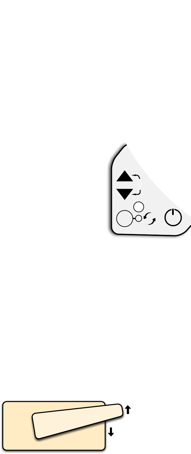
Water Heater (upgrade option “On Demand”)
Press the power button on the control panel. The heater automatically
begin heating. When the water is ran hot water will be available within
a few seconds you can adjust the temperature setting using the
up/down buttons. Range: 95° – 124° F.
Very cold, high pressure water may need to be throttled to prevent it
from passing through the system before it reaches temperature.
There is a flow control valve mounted to the water heater under the
rear dinette bench. If necessary, adjust this control to maintain heat.
14
LIGHT
PILOT HERE
OVEN
BURNER
120V
WATER
HEATER
WATER HEATER
ON RESET
Gas cooking appliances need fresh air for safe Gas cooking appliances need fresh air for safe
operation. Before operating: Open vents or operation. Before operating: Open vents or
windows slightly or turn on exhaust fan prior to windows slightly or turn on exhaust fan prior to
using cooking appliance. Gas ames consume using cooking appliance. Gas ames consume
oxygen, which should be replaced to ensure oxygen, which should be replaced to ensure
proper combustion. Improper use can result in proper combustion. Improper use can result in
death or serious injury.death or serious injury.
WARNING
!
c
WATER HEATER
ON/OFF
C/F
UP
DOWN

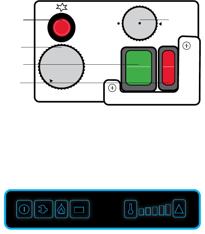
Air Conditioner
The roof air can be run in air conditioning mode or fan only mode as indicated by the
control knob. Turn this knob slowly. If you change a setting too quickly it may trigger
the overload protection and you will need to wait several minutes for it to auto reset.
There is a built in thermostat which can be adjusted by turning the knob toward red
for less cold or blue for more cold.
Optional Heat Mode
Your air conditioner may include a heat position on the control knob. This setting
will only be active if you purchased the optional heater unit.
Vent switch
(4) Directional vents
Fan/Heat* Selector
* if so equipped with heat
Temperature
OPTIONAL
HEAT
15
(drawing)
TT
16
1.9 Cubic Foot Refrigerator:
DOMETIC
RM2193
Propane Operation
Turn the LOW
-
MED
-
HI knob to MED.
Depress the knob while activating the
piezo ignition at the same time.
Slowly release the knob.
You can visually check the flame by
opening the small window cover on
the burner housing.
If there is air in the line, this process
may need to be repeated until the gas
reaches the burner.
Allow the refrigerator to cool, then use the LOW
-
MED
-
HI knob to adjust the temperature.
120 Volt Operation
With the Shore Power hooked up, turn on the green 120V switch. Allow the refrigerator to cool,
then use the 1 - 7 knob to adjust the temperature, 1 is least cold and 7 is most cold. DO NOT turn
on the 12V and 120V at the same time.
I
O
I
O
120V
1
0
7
3
5
-
-
-
on
off
•
low
•
med
•
high
•
off
12V
Refrigerator controller (outside the trailer, behind the refrig vent cover)
Propane
ignition
button
120V
temperature
knob
120V
on/off
switch
12V
on/off
switch
Propane
temperature
knob
3.7 Cubic Foot Refrigerator:
DOMETIC RM850
Propane Operation
Press the ON/OFF button until the control panel illuminates. Double press the propane button
(indicated by a picture of a flame) until it illuminates. If there is air in the lines, this process may
need to be repeated until the gas reaches the burner.
120 Volt Operation
Double press the ON/OFF button until the control panel illuminates. Double press the 120V button
(indicated by a picture of a household plug) until it illuminates.
12v Operation
The 12V setting is meant to aid in cooling while on the road and may not always reach ideal
refrigeration temperatures. It is not meant for continuous use.
Double press the ON/OFF button until the control panel illuminates.
Double press the 12V button (indicated by a picture of a battery) until it illuminates.
Do NOT use the 12V setting for regular use. The 12V setting is meant only to aid in
cooling while on the road and may not always reach ideal refrigeration temperatures.
- +
!

2.0 Cubic Foot Refrigerator:
Switch the refrigerator on by pressing the On/Off button.
Adjust Temperature
Press the temperature selection button repeatedly until the
desired temperature level is set.
The more LEDs light up above the button the lower is
the temperature level.
To switch from the last level to the first level press the
Temperature selection button again.
Setting the fast cooling function (CRX50, CRX65, CRX80 only)
The option of operating the refrigerator using a fast-cooling
function allows
temperatures suitable for freezing foods to be reached.
• Press the temperature button for longer than 3 seconds.
• The LED above the temperature button lights up.
• Press the temperature button again for longer than 3 seconds
to operate the refrigerator in normal mode.
6.0 Cubic Foot Refrigerator:
Propane Operation
Press and hold the control knob until the screen illuminates
(about one second)
Turn the knob to highlight the Flame icon.
Press the knob.
The screen will change to display available power settings.
Select the Flame icon.
120 Volt Operation
Press and hold the control knob until the screen illuminates (about one second)
Turn the knob to highlight the Electrical Plug icon.
Press the knob.
The screen will change to display available power settings.
Select the Electrical Plug icon.
12V Operation
Press and hold the control knob until the screen illuminates
(about one second)
Turn the knob to highlight the Battery icon.
Press the knob.
The screen will change to display available power settings.
Select the Battery icon.
Adjust Temperature
Press and hold the control knob until the screen illuminates
(about one second).Turn the knob to highlight the Temp gauge icon.
Press the knob. Turn the knob to change the temperature.
17
NOTE: To use any propane appliance you must first let gas into the lines by turning the tank
valve handle counter clockwise.
Propane Control Knob
Adjusting Temperature
120 Volt
12v
LEDs:
Temperature
levels
LED Blue: Compressor is running
LED Orange: Compressor is off
On/off button
Interior Light
IR sensor for
switching the
interior light
LED Service
display
Temperature
Selection Button
LED: Fast cooling
function on (CRX50,
CRX65, CRX80)
LED: Winter mode
on (CRX140ACDC)
18
+
-
OPEN
CLOSE
AUTO IN/OUT ON/OFF
HOLD
TO SET
78 F
Tank Level Monitors
Press the button to see the level of the associated tank.
The level will display as a percentage for several seconds and then turn off.
TV Antenna
Locate the cable plate near your TV and press the black button to send power to the antenna.
Go to the antenna control and turn on the slide switch mounted on the side of the panel.
Depress the directional control and rotate the antenna. As you rotate, the LEDs will
illuminate. The more LEDs, the better the signal strength. There is a small knob next
to the LEDs. You can use this to adjust the LED sensitivity to better dial in the signal.
Backup Camera
Turn on your tow vehicle. The camera will only have power when the marker lights
are on. In some vehicles you will have to turn these on at the dash. Pair the
monitor with the camera by following the included instructions. Check the
camera angle and adjust if needed.
Roof Fan
The roof fan can be operated by either the face panel or the included
remote control. The fan features: 10 speeds, reversible airflow and an auto
setting which will turn the fan on and off to maintain specified temperature.
Awning
Hook the awning crank wand into the eyelet. Turn until the awning extends 2ft to 3ft.
Unfold and extend the legs until they meet the ground.
Continue opening the awning, you may need to stop and move the legs further out.
To close the awning, follow the directions in reverse order. On either end of the
shroud there is a red guide “flag” This will retract when the awning reaches the
closed position.
An optional tension rafter is available for this awning. This helps keep the fabric tight
and prevents sag. It is available with or without LED lights.
Do not use the awning in windy conditions or in heavy rain.
Bumper Receiver
The 2” bumper receiver is rated for 250 lbs and is intended for use only with bicycle
or utility racks.
Do NOT use the receiver to pull a second trailer.
Toilet
Press down on the pedal to flush.
If there is not enough water in the bowl,
you can add more by lifting up on the pedal.
PRESS
DOWN TO
FLUSH
LIFT
UP TO
ADD
WATER

Making dinette and sofa into bed:
19
1. While supporting the front of the table with one
hand, press the latch release on top of leg.
*
Note: Always depress button before folding
or unfolding the leg.
3. Using both hands, lift front of table to let back
drop down to disengage the catches.
4. Swing out from wall and lower into recess
between benches.
5. Place backrest cushions over table to form
the bed.
*
Note: To avoid damage to the tabletop,
when pulling trailer, always travel
with this in the bed position.
2. Fold leg back under the table.
Side dinette table to bed:
1. While lifting up on the table, make a twisting
motion to disengage table from the leg.
3. Fit table top in recess between benches.
4. Place backrest cushions over table to form
the bed.
2. Lift and make a twisting motion to disengage the
leg from the floor.
20

Sofa to Bunk Beds:
1. Remove the lower seat cushion.
3. While holding the backrest in position,
install the bunk posts.
3A Insert the base into the lower bracket.
4. Hook the tab under the bunk into the bunk
post loop.
5. Place the lower seat cushion back down to
form the lower bed.
*
Note: To avoid damage to the bunks,
when pulling trailer, always travel
with this in the sofa position.
2. Lift the sofa backrest up.
21

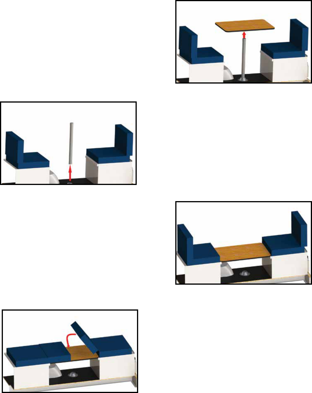
1. While lifting up on the table, make a twisting
motion to disengage table from the leg.
3. Fit table top in recess between benches.
4. Place backrest cushions over table to form
the bed.
2. Lift and make a twisting motion to disengage
the leg from the floor.
Front Dinette to Bed:
22

23
Maintenance and Cleaning
Battery Upkeep
The house battery is a wet cell and the water level will need to be maintained periodically. How often
will depend on battery use and ambient temperatures. Proper safety precautions must be taken
when working with the battery. It is recommended that this service be performed by a qualified
service technician.
Terminals and Connectors
Regularly inspect all electrical contacts, eyelets, terminals and connectors for corrosion or wear
which may degrade the electrical connection and lead to electrical malfunctions.
Axle Bearings
Bearings should be lubed every 5000 miles and visually inspected every 10,000 miles.
Lubrication:
Remove the rubber cap from the middle of the grease cover on the end of the spindle. Attach your
grease gun fitting to the zerk and add grease. Two or three pumps is generally sufficient. It is
recommended that the grease be added slowly while rotating the tire. This will reduce the risk of
pushing through the grease seal.
Visual Inspection:
Remove dust cap, cotter key, and castle nut. Slowly slide the hub from the spindle. Clean the interior
cavity of the hub. Remove bearings from spindle clean and remove old grease from bearings.
Visually inspect hub cavity and bearings for discoloration, damage, pitting, or flat spots, and check
rolling functionality. Replace parts if needed. Hand pack new grease into the bearings and
re-assemble. Add 5 extra pumps (for manual grease gun) or about a thimble sized amount of
grease into the chamber.
Water Heater Anode (for the Suburban model only)
The water heater tank contains an anode
which protects the tank from corrosion.
While in use, the anode should be
inspected every 3 months and
replaced if necessary. Always drain
the water heater tank when the
trailer is not in use.
Tank-less, On-demand water heaters
do not have an anode.
WATER
HEATER
DRAIN
RESET
BUTTONS
Water Filters
The fresh water and gray water pumps are equipped with stainless steel re-usable
debris filters. The fresh water pump filter is located in the passenger side rear bench.
The gray water filter is located beneath the trailer under the shower pan. Remove the
filter by turning the clear cover counter clockwise. Clean and re-install.
Air Conditioner Filter
The roof air conditioner has a re-usable fine mesh filter. To remove, gently pry the
tabs from the air cover and pop the filter from the housing.
Window Drain Openings
Most RV windows have drainage openings or “weep holes” in the bottom frame.
Check these openings monthly and clean if necessary. If they clog with pollen, leaves
or other debris, water may build up in the track and seep into the trailer cabin.
Cabinet Door Catch
The cabinet door roller catches may occasionally shift due to use or vibration.
To adjust: Loosen the screws, reposition the catch and tighten screws.
General Cleaning Information
Windows Window and glass cleaners.
Fiberglass Window cleaners or multi purpose cleaners.
Auto or marine polish and body wax.
Wood Cabinetry Furniture cleaners or furniture polish.
Cushions Upholstery cleaners/fresheners.
Cushion covers can be removed and machine
washed. Wash on cold/delicate. Dry on low heat.
Headliner Fabric and upholstery cleaners.
24

Storage and Winterization
Suspension
When storing for prolonged periods, it is a good practice to block up the trailer and relieve
stress on the suspension.
To do this jack up the trailer slightly and slide blocks or jack stands under the frame directly
behind the axle. The idea is not to lift the trailer completely off the ground but to take the
majority of weight off the axle torsion arms. When finished, lower the rear stabilizers to keep
the trailer steady. Use blocks under the stabilizer pads if needed.
Moisture Levels
Humidity can be an important factor depending on your climate. Left unchecked, humid air
inside the trailer can condense resulting in water damage and mold. In humid areas, the use
of either an absorbent or powered dehumidifier is recommended.
Battery Storage
The trailer battery should not be left outside in freezing weather for a prolonged period.
Doing so may freeze the electrolyte and destroy the battery. Store the battery in a heated space
or use a battery maintainer/trickle charger to keep the battery charged and prevent freezing.
Winterizing the Water System
To prepare for freezing conditions you will need to drain all water from the trailer and run
antifreeze through the water system.
Empty all Tanks
1. First you will need to go to the RV dump station and empty the black water and gray water
tanks. Rinse the tanks with clean water.
2. On the outside, passenger-side of the trailer, there is
the fresh water tank petcock valve on the bottom.
Turn the valve to let water drain from the tank
(this water will drain out the bottom of the trailer).
3. Open your hot water faucet taps (leave the pump off).
If you have a tankless water heater, skip step 3.
Lift the access cover on your rear dinette driver
side bench. At the back of the water heater, locate the
bypass valves, turn valve to the bypass configuration with
all handles aligned vertically (see image).
25
WATER HEATER (side view)
Shown in Bypass Configuration
(levers vertical)
Shown in Hot Water Configuration
(levers horizontal)
4. Outside the trailer: open the water heater maintenance panel and remove the anode plug to
let any water drain from the heater tank.
5. Close hot water taps.
Run Anti-freeze Through the Water Lines and Fixtures
1. Add RV anti-freeze to the fresh water holding tank. Most trailer layouts use 2-3 gallons.
2. Turn on your fresh water pump switch.
3. Go to each fixture and run the cold water side until you see only antifreeze (the anti-freeze is
typically colored pink or red)
• Kitchen sink
• Bathroom sink
• Bath shower head
• Toilet
• Outside shower head
• If you have a tankless water heater, run anti-freeze through the hot side
4. Turn off the fresh water pump
5. Go to the city water connection fitting and gently remove the mesh screen. Push the small
button-like protrusion to let water flow out the fitting until you see anti-freeze.
NOTE: If there is pressure in the line, water and anti-freeze may spray out with force.
Add Anti-freeze to the Drains
Pump or directly pour anti-freeze down the sink and shower drains.
1. Turn on the shower drain pump.
2. Look under the trailer to visually verify that the anti-freeze has passed the pump and is
traveling down the clear line leading back to the gray water tank.
3. Turn off the shower drain pump.
4. Open the dump valves and drain any excess water and antifreeze.
Re-install water heater anode.
Close all covers and caps.
26
De-winterization
Remove Anti-freeze from Lines and Fixtures
1. On the outside rear, passenger-side of the trailer, there is the fresh water tank petcock valve
on the bottom. Turn the valve to let anti-freeze drain from the tank (this will drain out the
bottom of the trailer, place a bucket underneath to catch the old anti-freeze).
2. Add water to the fresh water holding tank.
3. Turn on your fresh water pump switch.
4. Go to each fixture and run water through until you see only clear water and no color
(the antifreeze is typically colored pink or red).
• Kitchen sink
• Bathroom sink
• Bath shower head
• Outside shower head
5. Turn off the fresh water pump.
6. Go to the city water connection fitting and gently remove the mesh screen. Push the small
button-like protrusion to let water flow out the fitting until you see clear water.
NOTE: If there is pressure in the line, water and anti-freeze may spray out with force.
7. Drain any remaining water from the tank (this water will drain out the bottom of the trailer).
Sanitize Lines and Fixtures
1. Fill the fresh water holding tank with bleach sanitizing solution.
2. Turn on your fresh water pump switch.
3. Go to each fixture and run water through until you smell bleach.
• Kitchen sink
• Bathroom sink
• Bath shower head
• Outside shower head
4. Turn off the fresh water pump
5. Let sanitizer sit in the tank and lines for 4 hours then drain.
6. Remove fresh water filter and rinse.
27
Rinse Lines and Fixtures
(skip this step if you have a tankless waterheater)
1. Lift the access cover on your rear dinette driver-side bench. Go to the back of the water
heater and locate the bypass valves, turn to hot water configuration.
Outside the trailer: Open the water heater maintenance panel and verify the anode plug
is installed and snug.
2. Fill the fresh water holding tank with clean water.
3. Turn on your fresh water pump switch.
4. Go to each fixture and run water through until you no longer smell bleach.
• Kitchen sink
• Bathroom sink
• Bath Shower Head
• Outside Shower Head
5. Turn off the fresh water pump.
Spring checklist:
1. Battery: Charge your battery, then hook back up to your trailer.
2. Water System: See De-winterization on page 27.
3. Plumbing: Check the plumbing for any leaks.
4. Appliances: Check the gas supply, check the operation of all LP fired appliances. Do a leak
test and LP gas operation pressure test annually.
5. Tires: Check your air pressure. Inspect tires for any cracks, foreign objects.
6. Seams and sealants: Inspect seams and sealants for any cracking or separation, reseal
if needed.
7. Replace any batteries in smoke/CO2 detectors, thermostat, and check fire extinguishers that
they are fully charged.
Fall checklist:
1. Battery: If storing in a freezing climate, pull all batteries and store in room temperature area.
2. Water System: See De-Winterization on page 27.
3. Tires: Check tire pressure, fill to manufacturers specs.
4. Seams and sealants: Inspect seams and sealants for any cracking or separation, reseal
if needed.
28

Specifications
120v outlets Rated for 15 amp service
12v sockets Rated for 10 amp service
Group 24 Battery 52AH 88 ca/475 cca 125 min Reserve Capacity
Group 27 Battery 66AH 955 ca/650 cca 160 min Reserve Capacity
Wheel Lug Nut Torque 90 ft lbs.
Wheel Lug Nut Wrench Size 13/16”
Tire Pressure 6 ply, Load C 50 psi. Max.
Tire Pressure 8 ply, Load D 68 psi. Max.
Rear Stabilizer Nut Size: 3/4”
Anode Plug Size: 1-1/16”
Safety Precautions
At Scamp Trailers, nothing to us is more important than your safety. This
includes driving/towing safety, occupant safety, operational safety, and more. When you are dealing
with carbon monoxide producing appliances, propane gas, electricity, it is critical that safety become
your number one priority in and around your Scamp Travel Trailer.
Ball Height
(average height to top of ball)
13” 18 in.
16” 21 in.
19” 42 in.
The 2” bumper receiver is rated for 250 lbs and is
intended for use only with bicycle or utility racks.
Do NOT use the receiver to pull a second trailer.
Weight limit on front bunk bed (top bed) 150 lbs
Cargo Weight:
13 standard - 1100 lbs
13 deluxe - 900 lbs
16 standard - 1600 lbs
19 deluxe - 1000 lbs
* NOTE: Never exceed your tow vehicle’s maximum towing capacity!
29
The Safety Alert Symbol is used to warn of a The Safety Alert Symbol is used to warn of a
potential personal injury hazard. This symbol potential personal injury hazard. This symbol
is used in conjunction with the signal word or is used in conjunction with the signal word or
can be used alone. This symbol should be can be used alone. This symbol should be
used on both product safety labels and in used on both product safety labels and in
literature which can describe the potential literature which can describe the potential
hazard in greater detail.hazard in greater detail.
!

Troubleshooting
Problem Possible Cause Solution
Loss of 12v power
from Battery
Loss of 12v power
or charge from
Shore Power hookup
Loss of 12v power
or charge from tow
vehicle
Battery looses
charge quickly
Battery fuse or
Main fuse blows
when connected
to TV
Battery does
not charge
Water Heater is not
working on propane
Disconnect switch is turned OFF
Low Battery
Blown 12v fuse
(see Breakers and
Fuses page 8
)
Loose or corroded wiring
connection.
Blown 12v fuse (see Breakers and
Fuses page 8)
Converter power cable has
come
unplugged
Blown 12v fuse (see Breakers and
Fuses page 8)
7 Way connector is loose, dirty
or faulty
Inadequate wiring/power output
from Tow vehicle
Loose or corroded wiring
connection to battery
Tow vehicle wiring is not properly
isolated and intermittently draws
power from battery
Battery is not reaching a complete
charge before each use. (12.6V
to 12.8V)
High power consumption or
power drain
Battery has reached end of service
life or has been drained too far and
is damaged
High power consumption or
power drain
Battery was let drain too far before
charging which creates high load
Tow vehicle wiring is not properly
isolated and intermittently draws
power from battery
Disconnect switch is turned OFF
Blown 12V fuse (see Breakers and
Fuses page 8)
Charge source is not
operating correctly
Propane tank is empty
Battery power is too low to fire ignition
Air in the lines
Over-temp safety has been triggered
Turn switch ON
Charge battery
Replace fuse
Secure wiring. Clean or replace
any corroded terminals
Replace fuse
Plug into adjacent outlet
Replace fuse
Re-seat, clean, or replace connector
Have vehicle tested
Secure terminals, clean or replace
any corroded connectors
Service tow vehicle
Check charge source:
Charge voltage should be 13.6V to 14.4V.
The lower voltage takes more time to charge
Unplug any high consumption 12V aftermarket
accessories. Check for other power drain:
Refrigerator on 12V, breakaway switch engaged.
Replace battery
Unplug any high consumption 12V aftermarket
accessories. Check for other power drain:
Refrigerator on 12V, breakaway switch engaged.
Use separate charger to begin charging
or use shore power
Service tow vehicle
Turn switch ON
Replace fuse
Check charge source:
Charge voltage should be 13.6V to 14.4V.
The lower voltage takes more time to charge
Refill tank
Re-charge battery or use shore power
Run cook-top to help bleed lines
Press to reset (located in outside heater panel)
30

Troubleshooting
(continued)
Problem Possible Cause Solution
Water Heater is not
working on electric
Refrigerator alarm
is beeping
Refrigerator does
not run on propane
Roof Fan beeps
Roof Fan
spontaneously
turns on or off
Water Pump is
not working
Water tank is filling
from city water
Co2/LP Detector
beep (not alarm)
Brakes are locking
Shore Power hookup is not receiving power
Breaker is in the off position
Maintenance switch is in the OFF position
Low battery power alarm
Open door alarm
Propane tank is empty
Battery power is too low to fire ignition
Air in the lines
Low battery
Auto-temp feature is activated
Low battery
Remote control error
Clogged filter
Air is being pulled into line
Blown fuse
Pump check valve is stuck.
Pump check valve is damaged
Low battery
“End of service life” indicator
Brake control is set too high
Brake control is out of calibration
Breakaway switch plunger has been pulled loose
Brake mechanism is out of adjustment
Check 30a power source and plug
Turn on
Turn to ON (located in outside heater panel)
Charge or use shore power
Close door tightly. If alarm persists,
adjust catch forward.
Refill tank
Re-charge battery or use shore power
Run cook-top to help bleed lines
Charge battery
or use shore power
Disable auto-temp
Charge battery
or use shore power
Turn both fan and remote off and back on. Pull fuse
Clean filter
Tighten fittings
Change fuse (see Breakers and Fuses page 8)
Rap lightly on pump to loosen valve
Replace pump
Charge battery
or use shore power
Replace detector
Lower setting*
Re-calibrate controller*
Re-seat plunger
Have brakes serviced
31
* If you are having any Autowbrake system issues please call 319-521-2310.
For FAQs and more info: https://getautowbrake.com
* Note: To disable brakes, follow
the 7-way wire into the interior of the trailer, pull the fuse in the brake box (see page 4). This will disable the braking system, while maintaining the trailer lights connection.
IMPORTANT LINKS TO HAVE: (for specific manufacturer’s operation information and manuals)
DOMETIC PRODUCTS: www.dometic.com • FIAMMA AWNINGS : www.fiamma.it • MAXXAIR fans: www.airxcel.com/rv/maxxair • Contoure microwaves: www.contoureusa.com
Suburban Furnace, cooktop and water heaters: www.airxcel.com • ASA Jensen: www.jensen-electronics.com • Emerson Thermostat: www.climate.emerson.com
King Connect Antenna: www.kingconnect.com • Progressive Dynamics converters/fuses: www.progressivedyn.com • Lippert Windows: www.lci1.com
Lippert Axle: www.lci1.com/manufacturing/axles • Stromberg Carlson 19’ landing gear: www.strombergcarlson.com • Furrion Backup Cameras: www.
flowaterpump.com

32

33
ELECTRICAL SYSTEM PLUMBING SYSTEM

34
ELECTRICAL SYSTEM PLUMBING SYSTEM

507 State Hwy. 371 NW P.O. BOX 2 Backus, MN 56435 scamptrailers.com I MN Res.: 218-947-4932 Toll Free 800-346-4962
Notes:
05.2022
