
installation instructions
Smart Slide Door
Contents
Page No.
Introduction……………………………………………………………….1
Important Instructions…………………………………………………….1
Materials and Tools Required…………………………………………....2
Rough Openings………………………………………………………….. 2
Terminology……………………………………………………………….3
Sealant Joint Placement………………………………………………….. 4
Smart-Slide Door Install- Fixed Sash Jamb - Outside …...........….….. 7
Smart-Slide Door Install - Fixed Sash Sill - Outside ………..………... 8
Protective Film Handling………………………….…………………….. 5

EUROLINE
Windows
1
© EuroLine Windows Inc
Instructions Rev. 3 2022
Important
Leaving tightly spaced
windows/doors in the sun can result
in overheating of the sealed units and
extrusions, which may result in
damage. Ensure that product is
secured to a wall to prevent any
damage
Important
Improper installation may void all
warranties expressed or implied.
Installation Instructions are also
available on our website.
Contact Information
EuroLine Windows Inc.
7620 MacDonald Road,
Delta BC V4G 1N2
Telephone: 604-940-8485
Fax: 604-940-8486
Toll-Free: 1-800-337-8604
Web Site: 1-800-337-8604
Introduction
Important Instructions
Please read before you start installation
RECEIVING:
Carefully inspect all windows and doors at the time you receive them and
again at the time you install them. Any visible defects with the product must
be reported to EuroLine before installation begins.
HANDLING:
Window and door units are to be handled carefully to avoid damage. They
must be moved in the vertical position. If the product is supplied with a
flange it must rest on shipping blocks that are temporarily attached.
COLD WEATHER CAUTION: Use special care when handling or
installing below 5° C (40°F). Avoid any impact to frames, sash, or glazing
beads.
STORAGE:
Store the units at a slight lean against a wall on a flat, level area, undercover.
Allow adequate spacing between the products for ventilation.
BUILDING CODES:
It is the responsibility of the owner, architect, or builder to select and install
products in compliance with applicable laws, regulations, and building
codes.
BUILDING ENVELOPE:
To minimize the danger of leakage at window openings, various other items,
such as properly configured head flashings, perimeter penetration flashings,
sealant joints, building wraps, and similar components, are of critical
importance. Typically, some of these components need to be installed prior
to the window installation, while others must follow the window installation.
The specific configurations of such flashings and similar components are
dependent on the specific wall construction and assembly and should be
determined by the project architect, a building envelope specialist, or a
similar design professional. This manual does not address such items, and
EuroLine is not responsible for the proper design or installation of these.
INSTALLATION:
Proper installation is necessary for this window or door to perform as
designed and rated for water and air resistance. EuroLine products must be
installed plumb, level, and square.
SHOP DRAWINGS:
If you have EuroLine shop drawings, refer to these for specific installation
instructions.

EUROLINE
Windows
2
© EuroLine Windows Inc
Instructions Rev. 3 2022
CARE AND MAINTENANCE:
Protect windows/doors from welding splatter, grinding sparks, concrete,
mortar, stucco, paint, and other harmful construction materials. To clean
vinyl, use a mild soap and water solution. To clean the glass, use a soft, grit-
free cloth and glass cleaner. On all operable windows and doors, keep the
channel at sill free of debris and protect sills from traffic damage. Keep all
weep holes open for proper drainage. The protective film must be removed
on completion of installation. Clean and lubricate all hardware after
construction. Ongoing maintenance and adjustments are described in our
maintenance manual, available by contacting our sales office or visiting our
website.
PERFORMANCE DATA:
Our products are tested to ASTM test standards, CSA A440 Standards, and
are NFRC certified for thermal performance. Data is available upon request.
Materials and tools
Tools Materials
- Spirit level - Shims: use non-deteriorating,
- Framing hammer non-swelling, hard plastic (4"x1 ½ ")
- Screwdriver/screw gun of several thicknesses to suit. Shims
- Tape measure may be purchased from Euro-Line
- 11 mm wrench Windows in thickness of 2,3,4,5, and
- 4 mm Allen key 6 mm.
- 2” Gal
vanized Roofing Nails (10 ½
ga.)
-1 ½” #
10 Pan Head Tapping Screws
(cad plate
d)
Rough Openings
Make sure that the rough openings are square, and that they have a level sill
and plumb (vertical) jambs. Make sure that the outside face of the wall is
straight and plumb. If a rough opening is out-of-square, adjust the thickness of
the shim blocks as necessary to make sure that you install the window or door
frame in a square, level and plumb way.
If you see any rough openings that are not acceptable for frame installation,
tell the general contractor or the party responsible for the construction. Get
written authorization from the general contractor or from the responsible
party before you install frames in unacceptable openings.
EUROLINE
Windows
3
© EuroLine Windows Inc
Instructions Rev. 3 2022
Make sure that the general contractor corrects the rough opening if you find the
rough opening does not allow you to install the frame perfectly level, square,
straight in every direction and plumb, and does not provide a minimum of 3/8"
(10 mm) and no larger than 1/2" (12 mm) clearance between the top of the
frame and the top of the rough opening.
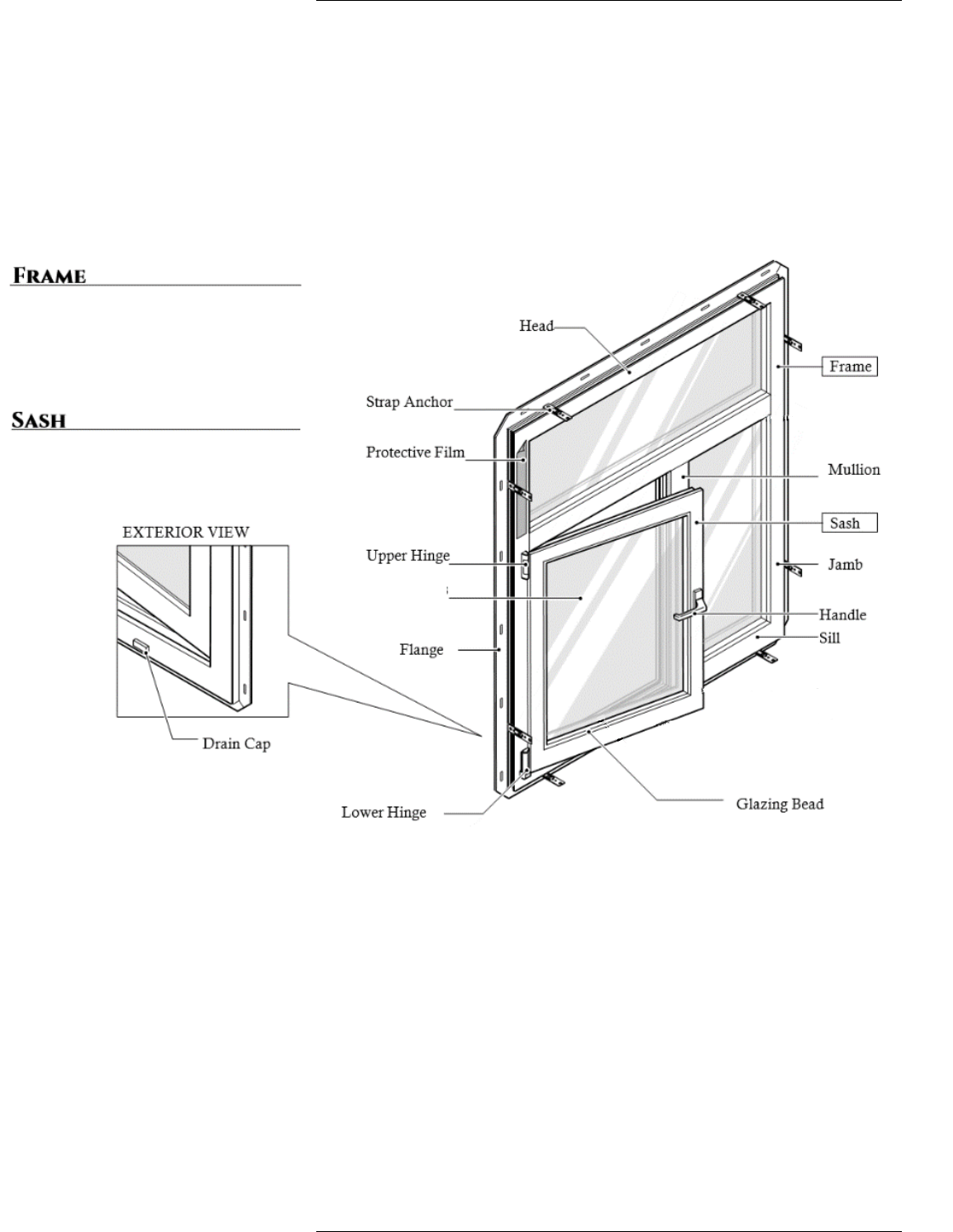
turn window
The fixed parts of the window or door.
The frame includes the head, jambs, sill,
and mullions. The frame does not include
the sash.
The movable part of the window or door.
Sealed Unit
Terminology of tilt & turn window

EUROLINE
Windows
4
© EuroLine Windows Inc Instructions Rev. 3 2022
Sealant Joint Placement
Sealants – Important Notes
Design of sealant joints and the selection of sealants are not the responsibility
of Euroline Windows. Sealants must be compatible with the window
materials to which they adhere. Check with your sealant supplier that the
sealant is compatible with the uPVC, the laminate covering the uPVC, metal
surfaces, caulked surfaces, or any other material of the window system to
which you plan to have a sealant joint.
If you are unsure as to the material composition of the window, contact
EuroLine Windows for more information.
The placement of the sealant joint must be located as shown on the cross-
sections below (location “A”). Care must be taken not to bridge the closeout
strip, or impede water exiting the drains on the face of the frame at the sill.
The same practice applies to other frames that are not included below.
CAUTION:
The close-out strip is not designed for air and water tightness.
To ensure an air and water seal, joint placement is as shown in
one or more of the locations shown “A”.
The sealant joint must be 7/8” (22mm) below drain caps on the
sill.

EUROLINE
Windows
5
© EuroLine Windows Inc Instructions Rev. 3 2022
Considerations
PFG Protective Film has been tested for
resistance to chemicals commonly found in
building and window manufacturing. These
include, but was not limited to:
- Resistance to water and air based
stains
- Paints and varnishes
- Adhesives
- Sealants
- Cement
- Stucco and brick wash solution
(muriatic acid) 20 to 1 dilution
Note
The above list is not an exhaustive. The
chemical makeup of products can be
reformulated over time. If in doubt, test for
exposure compatibility. Exposure to any
chemicals should be kept to a minimum.
Buckling of film may occur if environmental
or situational temperatures exceed 60ºC.
Protective Film Removal
PFG Protective Film protects glass surfaces against damage during shipping,
handling, and damage caused by other trades during construction. This clear
protective film can be applied to the outboard surface #1 or in combination with
surface #4 of dual IGUs, or surface #6 for triple IGUs.
Timeline for Removal
PFG Protective Film applied to the outboard surface #1 should be removed
within 9 months of delivery for best results. The film should be removed at a glass
temperature between 0º and 60ºF (-17 Cº and 15Cº). Typically, as the film is
exposed to UV, humidity and heat, the adhesion of the film to glass will increase.
In addition, as the temperature at removal decreases, the adhesion of the film to
glass will typically increase. Under normal circumstances, removing the film
within 9 months will help ensure easy removal with little to none of the film
adhesive remaining on the glass.
Use of high absorption coatings, tints, or Cardinal i89 Low-E on surfaces #4 or
#6, may affect adhesion. As such, it is advised to remove the film a few months
less than the allotted 9 months.
PFG Protective Film is applied in horizontal lengths overlapping from edge to
edge. To facilitate removal, start from one edge of the overlapping regions and
pull away from each strip of film. A plastic scraper or plastic putty knife can be
used to help where removal requires assistance. Do not use knives, razors, or any
sharp metal blades.
Any remaining adhesive can be removed using a citrus-based cleaner. Any
residual lines left behind that are visible during wet conditions are similar to those
of suction cup marks. They are not classified as defects.
Should you have any questions, please contact your EuroLine Windows Design
Representative.
Removing the film may result in static
discharge. To help reduce the chances of
static discharge, consider wetting the film
and/or reducing the speed of removal. Do
not remove film in the presence of flammable
or explosive chemicals. Including materials
or substances that come in contact with these
chemicals.
Caution

EUROLINE
Windows
6
© EuroLine Windows Inc Instructions Rev. 3 2022
Handling
IGUs with PFG Protective Film can be handled using suction cups. Some air may
become trapped under the film. This air will typically dissipate with time. Center
the cups over the overlapping layers of film for best results.
Location Key
1. Suction cup completely on upper layer --- Recommended Placement
2. Suction cup partially on overlap area, partially on upper layer--- Not
Recommended Suction cup on completely on overlap --- Recommended Placement
3. Suction cup partially on the overlap and partially on lower layer --- Not
Recommended Suction cup completely on lower layer --- Recommended
Placement
4. Suction cup over any edge of protected area --- Not Recommended
DO NOT pressure wash the film as it may
cause the film to lose adhesion.
Note

Fixed Sash Jamb - Outside
Series 3800 Smart-Slide Door Install - OX & XO Configurations
Drawing #:3800-DR-SSD-FS-JAMB-INSTALL-OX-R2
Date: 18 SEPT. 2020
Scale: 1:2
Fastening Through External Perimeter Frame
(Denoted by F )
Applies to all perimeter frame sides (Head, Sill & Jambs)
- Pre-drill 5mm (3/16") diameter hole through both
sides of uPVC frame and galvanized steel tube
- Drill 10mm (13/32") diameter hole though first inner
uPVC frame wall and first layer of galvanized steel tube
wall
- Ensure proper shimming at each fastener location
- Fasten through hole using #10 x 3-1/2" Panhead
corrosion resistant fastener
(Do
not over torque as this may distort the frame)
- Plug hole in uPVC frame using 10mm PVC plug
(black or white color)
F
ELEVATION VIEW
(EXTERIOR SIDE)
31
ACB
42
PLAN VIEW
(EXTERIOR SIDE)
F
F
F
F
F
F F
F
F
F
F
FASTENER LOCATIONS
ELEVATION VIEW
F
B
Left cross section:
Fixed door sash jamb - outside
1-2
Finishing 1/2" (13mm) PVC Plug
for
13/32" (10mm) to 7/16" (11mm) hole
(Black or white color)
7
© EuroLine Windows Inc Instructions Rev. 3 2022

Fixed Sash Sill - Outside
Series 3800 Smart-Slide Door Install - OX & XO Configurations
SILL
2
PLAN VIEW
EXTERIOR SIDE
ELEVATION VIEW
EXTERIOR SIDE
31
ACB
42
Drawing #:3800-DR-SSD-FS-SILL-INSTALL-OX-R2
Date: 18 SEPT. 2020
Scale: 1:2
SHIM LOCATIONS
ELEVATION VIEW
F
S
S
S
S
S
S
S
S
S
S S S S S
X
X
Finishing 1/2" (13mm) PVC Plug
for
13/32" (10mm) to 7/16" (11mm) hole
(Black or white color)
8
©
EuroLine Windows Inc
Instructions Rev. 3 2022

EUROLINE
Windows
© EuroLine Windows Inc Instructions Rev. 3 2022
For more information on these quality products
please contact:
EuroLine Windows Inc.
7620 MacDonald Road
Delta, BC. CanadaV4G1N2
T. 604.940.8485
F. 604.940.8486
E.
service@euroline-windows.com
W. www.euroline-windows.com
Toll Free: 1 800 337.8604
Other publications available from EuroLine Windows Inc. can be
found on our website (www.euroline-windows.com).
Do not reproduce this manual without prior written permission from Euroline Windows Inc.
