
VEMU INSTITUTE OF TECHNOLOGY
(Approved by AICTE, New Delhi & Affiliated to JNTUA, Anantapuramu)
P.KOTHAKOTA, NEAR PAKALA
CHITTOOR-517112, ANDHRA PRADESH
BASIC CIVIL ENGINEERING
LABORATORY MANUAL
DEPARTMENT OF CIVIL ENGINEERING

BASIC CIVIL ENGINEERING LABORATORY
MANUAL
(20A01304)
Department of Civil Engineering
VEMU INSTITUTE OF TECHNOLOGY:: P.KOTHAKOTA
NEAR PAKALA, CHITTOOR- 517112
Approved by AICTE, New Delhi & Affiliated to JNTUA, Anantapuramu
NAME
:
H.T.NO
:
YEAR/ SEMESTER :
JAWAHARLAL NEHRU TECHNOLOGICAL UNIVERSITY - ANANTAPUR
II B.Tech I Sem (Civil Engineering)
Basic Civil Engineering Laboratory – 20A01304
List of Experiments
1) Setting out of a building: The student should set out a building (single room only) as per the
given building plan using tape only.
2) Setting out of a building: The student should set out a building (single room only) as per the
given building plan using tape and cross staff.
3) Construct a wall of height 50 cm and wall thickness 1½ bricks using English bond (No mortar
required) - corner portion – length of side walls 60 cm.
4) Construct a wall of height 50 cm and wall thickness 2 bricks using English bond (No mortar
required) -corner portion – length of side walls 60 cm.
5) Computation of Centre of gravity and Moment of inertia of a given rolled steel section by
actual measurements.
6) Installation of plumbing and fixtures like Tap, T-Joint, Elbow, Bend, Threading etc;
7) Plastering and Finishing of wall
8) Application of wall putty and painting a wall
9) Application of base coat and laying of Tile flooring of one square meter
10) Preparation of soil cement blocks for masonry and testing for compressive strength
11) Casting and testing of Fly ash Blocks
12) Preparation of cover blocks for providing cover to reinforcement

CONTENTS
BASIC CIVIL ENGINEERING
II B.Tech – I Sem (20A01304)
S.NO
EXPERIMENTS
Page No
1
Setting out of a building
2
Setting out of a building
3
Constructing a wall
4
Constructing a wall
5
Computation of Centre of gravity and Moment of inertia
6
Installation of plumbing and fixtures
7
Plastering and Finishing
8
Application of wall putty and painting a wall
9
Application of base coat and laying of Tile
10
Preparation of soil cement blocks for
11
Casting and testing of Fly ash Blocks
12
Preparation of cover blocks

GENERAL INSTRUCTION FOR LABORATORY CLASSES
DO’S
1.
Without Prior permission do not enter into the Laboratory.
2.
While entering into the LAB students should wear their ID cards.
3.
The student should come with proper uniform.
4.
Student should sign.in the LOGIN REGISTER before entering into the laboratory.
5.
Students should come with observation and record to the laboratory.
6.
Student should maintain silence inside the laboratory.
7.
After completing the laboratory exercise, make sure to shut down the system properly.
DON’T’S
1.
Students bringing the bags inside the laboratory.
2.
Student using the computer improperly.
3.
Students scribbling on the desk and mishandling the chairs.
4.
Student using the mobile phone inside the laboratory.
5.
Student making noise inside the laboratory.
SCHEME OF EVALUATION
S.No
Program
Date
Marks Awarded
Total
(30M)
Record
(10M)
Observation
(10M)
Viva
Voice(5M)
Attendance
(5M)
1
Setting out of a
building
2
Setting out of a
building
3
Constructing a wall
4
Constructing a wall
5
Computation of
Centre of gravity and
Moment of inertia
6
Installation of
plumbing and fixtures
7
Plastering and
Finishing
8
Application of wall
putty and painting a
wall
9
Application of base
coat and laying of Tile
10
Preparation of soil
cement blocks for
11
Casting and testing of
Fly ash Blocks
12
Preparation of cover
blocks
Signature of Lab In-charge
VEMU INSTITUTE OF TECHNOLOGY::P.KOTHAKOTA
Chittoor – Tirupathi National Highway, Near Pakala, Chittoor(Dt.), AP – 517112
(Accredited by NAAC & NBA (CSE, ECE, EEE))
(Approved by AICTE, New Delhi & Permanently Affiliated to JNTUA, Anantapuramu)
VISION & MISSION OF THE INSTITUTE
Institute Vision
To be a premier institute for professional education producing dynamic and vibrant force of technocrats
with competent skills, innovative ideas and leadership qualities to serve the society with ethical and
benevolent approach.
Institute Mission
To create a learning environment with state-of-the art infrastructure, well equipped laboratories, research
facilities and qualified senior faculty to impart high quality technical education.
To facilitate the learners to foster innovative ideas, inculcate competent research and consultancy skills
through Industry-Institute Interaction.
To develop hard work, honesty, leadership qualities and sense of direction in rural youth by providing
value based education.
VEMU INSTITUTE OF TECHNOLOGY::P.KOTHAKOTA
Chittoor – Tirupathi National Highway, Near Pakala, Chittoor(Dt.), AP – 517112
(Accredited by NAAC & NBA (CSE, ECE, EEE))
(Approved by AICTE, New Delhi & Permanently Affiliated to JNTUA, Anantapuramu)
Department Vision
To become a premier center of excellence in Civil Engineering producing dynamic and energetic
force of Civil Engineers with competent skills, innovative ideas and leadership qualities to serve the
society with quality education, strong ethical values and research.
Department Mission
To impart high quality technical education in Civil Engineering by providing state – of – the – art
infrastructure, well equipped laboratories, research facilities and the qualified senior faculty.
To foster and inculcate innovative ideas, competent skills and consultancy services in learners through
institute-industry interaction.
To develop necessary leadership qualities, ethical values and communication skills in graduates by
providing the value based education.

VEMU INSTITUTE OF TECHNOLOGY::P.KOTHAKOTA
Chittoor – Tirupathi National Highway, Near Pakala, Chittoor(Dt.), AP – 517112
(Accredited by NAAC & NBA (CSE, ECE, EEE))
(Approved by AICTE, New Delhi & Permanently Affiliated to JNTUA, Anantapuramu)
Ptogramme Educational Objectives (PEO’S)
S.No
After few years of graduation the Civil Engineering student will be
PEO_1
To excel in the field of Civil Engineering by applying the fundamentals of
mathematics, basic sciences and engineering concepts to solve the real world problems.
PEO_2
To compete professionally with design competence and multidisciplinary approach by
applying suitable modern technological, research and consultancy skills in Civil
Engineering and allied areas.
PEO_3
To exhibit strong leadership qualities, ethical, environmental and professional values,
communication skills and also lifelong learning for sustainable development of society
and nation
Ptogramme Specific Outcomes (PSO’S)
After the graduation the Civil Engineering student will be
PSO_1
Higher Education: Qualify in competitive examinations for pursuing higher education
by applying the fundamental concepts of Civil Engineering domains such as Structural
Engineering, Geotechnical Engineering, Water Resources Engineering, Transportation
Engineering etc..
PSO_2
Employment: Get employed in allied industries through their proficiency to find
innovative solutions for challenges and problems in various domains of Civil
Engineering

VEMU INSTITUTE OF TECHNOLOGY::P.KOTHAKOTA
Chittoor – Tirupathi National Highway, Near Pakala, Chittoor(Dt.), AP – 517112
(Accredited by NAAC & NBA (CSE, ECE, EEE))
(Approved by AICTE, New Delhi & Permanently Affiliated to JNTUA, Anantapuramu)
Programme Outcomes (PO’s)
PO_1
Engineering Knowledge: Apply the knowledge of mathematics, science, engineering fundamentals,
and an engineering specialization to the solution of complex engineering problems.
PO_2
Problem analysis: Identify, formulate, review research literature, and analyze complex
engineering problems reaching substantiated conclusions using first principles of mathematics,
natural sciences, and engineering sciences.
PO_3
Design/development of solution: Design solutions for complex engineering problems and
design system components or processes that meet the specified needs with appropriate
consideration for the public health and safety, and the cultural, societal, and environmental
considerations.
PO_4
Conduct investigations of complex problems: Use research-based knowledge and research
methods including design of experiments, analysis and interpretation of data, and synthesis of the
information to provide valid conclusions.
PO_5
Modern tool usage: Create, select, and apply appropriate techniques, resources, and modern
engineering and IT tools including prediction and modeling to complex engineering activities
with an understanding of the limitations.
PO_6
The engineer and society: Apply reasoning informed by the contextual knowledge to assess
societal, health, safety, legal and cultural issues and the consequent responsibilities relevant
to the professional engineering practice.
PO_7
Environment and sustainability: Understand the impact of the professional engineering
solutions in societal and environmental contexts, and demonstrate the knowledge of, and
need for sustainable development.
PO_8
Ethics: Apply ethical principles and commit to professional ethics and responsibilities and
norms of the engineering practice.
PO_9
Individual and team work: Function effectively as an individual, and as a member or leader in
diverse teams, and in multidisciplinary settings.
PO_10
Communication: Communicate effectively on complex engineering activities with the
engineering community and with society at large, such as, being able to comprehend and write
effective reports and design documentation, make effective presentations, and give and receive
clear instructions.
PO_11
Project management and finance: Demonstrate knowledge and understanding of the
engineering and management principles and apply these to one’s own work, as a member and
leader in a team, to manage projects and in multidisciplinary environments.
PO_12
Life – long learning: Recognize the need for, and have the preparation and ability to engage in
independent and life-long learning in the broadest context of technological change.

VEMU INSTITUTE OF TECHNOLOGY::P.KOTHAKOTA
Chittoor – Tirupathi National Highway, Near Pakala, Chittoor(Dt.), AP – 517112
(Accredited by NAAC & NBA (CSE, ECE, EEE))
(Approved by AICTE, New Delhi & Permanently Affiliated to JNTUA, Anantapuramu)
Course Outcomes (CO’S)
CO 1
Identify tools and equipment used and their respective functions.
CO 2
Identify different types of materials and their basic properties.
CO 3
Use and take measurements with the help of basic measuring tools/equipment
CO 4
Select proper tools for a particular operation.
CO 5
Select materials and tools to make a job as per given specification/drawing

EXPERIMENT NO-1
SETTING OUT OF A BUILDING
AIM: The student should set out a building (single room only) as per the given building plan
using tape only.
APPARATUS:
1.
Thread 2. Pin 3.Tap 4.Ranging rods
PROCEDURE
1.
From the plan (fig 1), the centre line of the walls are calculated. Then the centre lines
of the rooms are set out by setting perpendiculars in the ratio 3:4:5. Suppose the corner
points are a, b, c, d, e, f and g which are marked by pegs with nails on top.
2.
The setting of the corner point is checked according to diagonals ac, bd, cf and eg
3.
During excavation, the centre points a, b, c, d, e, f, g may be removed. Therefore the
centre lines are extended and the centre points are marked about 2m away from the
outer edge of excavation.
4.
Thus the points A1, A2, B1, B2 and likewise, are marked outside the trench. Centre
line is shown clearly by stretching thread or rope. The centre points fixed 2m away
from the excavation are marked with sit out pegs.
5.
From the plan details, the width of excavation to be done is also marked by thread with
pegs at appropriate positions.
6.
The excavation width is then marked by lime or by with furrow with spade.
7.
If the plan is much to complicate and follows a zigzag pattern, then the centre pegs are
kept at suitable positions according to site conditions.

SETOUT OF A BUILDING PLAN
RESULT:

EXPERIMENT 2
SETTING OUT OF A BUILDING BY TAPE AND CROSS STAFF
AIM: The student should set out a building (single room only) as per the given building plan using
tape only.
APPARATUS:
1.
Thread 2. Pin 3.Tap 4.Ranging rods 5.Cross staff
PROCEDURE
1.
From the plan (fig 1), the centre line of the walls are calculated. Then the centre lines
of the rooms are set out by setting perpendiculars in the ratio 3:4:5. Suppose the corner
points are a, b, c, d, e, f and g which are marked by pegs with nails on top.
2.
The setting of the corner point is checked according to diagonals ac, bd, cf and eg
3.
During excavation, the centre points a, b, c, d, e, f, g may be removed. Therefore the
centre lines are extended and the centre points are marked about 2m away from the
outer edge of excavation.
4.
Thus the points A1, A2, B1, B2 and likewise, are marked outside the trench. Centre
line is shown clearly by stretching thread or rope. The centre points fixed 2m away
from the excavation are marked with sit out pegs.
5.
From the plan details, the width of excavation to be done is also marked by thread with
pegs at appropriate positions.
6.
The excavation width is then marked by lime or by with furrow with spade.
7.
If the plan is much to complicate and follows a zigzag pattern, then the centre pegs are
kept at suitable positions according to site conditions.

SETOUT OF A BUILDING PLAN
RESULT:

EXPERIMENT 3
CONSTRUCTION OF A WALL
AIM: Construct a wall of height 50 cm and wall thickness 1½ bricks using English bond (No
mortar required) - corner portion – length of side walls 60 cm.
APPARATUS:
1.
Bricks 2. Cement 3.Sand
PROCEDURE:
Bricks
The quality of bricks to be used in masonry construction should be of standard specifications
(good brick earth, thoroughly burnt and deep cherry red or copper in color). Bricks should be
regular in shape and their edges should be sharp. Bricks should emit a clear ringing sound on
being struck and should be free from cracks, chips, flaws and lumps of any kind. Bricks should
not absorb water more than one-sixth of their weight after one-hour soaking by immersing in
water. Standard bricks should have a crushing strength of 105 kg/sq.cm or 1500 lbs/sq.in.
Mortar
Mortar should be of the specified grade and materials used for mortar should be of standard
specifications.For cement mortar, cement should be fresh Portland cement or pozzolana Portland
cement of standard specifications. Sand should be sharp, clean, and free from organic and
foreign matters. Coarse or medium-sized sands should be used for rich mortar, and local fine
sand may be used for weak mortar The proportion of cement-sand for mortar can vary from 1:3
to 1:6 or as specified. Materials of mortar should be measured to have required proportion with
measuring box. Cement and sand should first be dry-mixed to have a uniform color on a clean
masonry platform and then mixed by adding clean water slowly and gradually to have workable
consistency and mixed thoroughly by turning at least three times.
Only freshly mixed mortar should be used for construction; old and stale mortar should not be
used. Mortar for one hour’s work should only be mixed with water so that they can be used
before setting starts.
2.
Soaking of Bricks
Bricks should be fully soaked in clean water by submerging in a tank for a period of 12 hours
immediately before use. Soaking should be continued till the air bubbles have ceased to appear.
3.
Laying of Bricks
Bricks should be laid in English bond unless specified and should be well bonded. Every course
should be truly horizontal, and walls should be truly in plumb. Vertical joints of consecutive

course should not come directly over one another; vertical joints in the alternate course should
come directly over one another.
No damaged or broken bricks should be used. Closers should be of clean-cut bricks and should
be placed near the ends of walls but not at the other edge. Selected best-shaped bricks should be
used for face work.
Mortar joints should not exceed 6 mm (1/4 inch) in thickness and joints should be fully filled
with mortar. Bricks should be laid with frogs upward except in the top course where frogs should
be placed downwards.
Brickwork should be carried out for not more than 1 metre or 3 feet in height at a time. When
one part of the wall has to be delayed, stepping should be left at an angle of 45 degrees.
Corbelling or projections, where made, should not be more than ¼ brick projections in one
course. All joints should be raked and faces of wall are cleaned at the end of each day’s work.
4.
Curing of Brickwork
The brickwork should be kept wet for a period of at least 20 days after laying. At the end of
day’s work, the tops of walls should be flooded with water by making small weak mortar edging
to contain at least 2.5cm or 1 inch deep water.
5.
Protection for Brickwork
The brickwork should be protected from the effect of sun, rain, frost etc. during the construction
since it is green and likely to get damaged.
6.
Scaffolding for Brickwork
Necessary and suitable scaffolding should be provided to facilitate the construction of a brick
wall. Scaffolding should be sound and strong with supports and members sufficiently strong to
withstand all loads likely to come upon them.
7.
Measurement of Brickwork
Brickwork should be measured in cubic meter or cubic feet. Different kinds of brickwork with
different mortar should be taken under separate items. The thickness of the wall should be taken
as the multiple of half brick as 10cm, one brick as 20cm, 1.5 bricks as 30 cm and so on. The rate
should include the cost of complete work including scaffolding and all tools and plants.
Laying of Bricks

Types of Bond
RESULT

EXPERIMENT 4
CONSTRUCTING A WALL
AIM: Construct a wall of height 50 cm and wall thickness 2 bricks using English bond (No
mortar required) -corner portion – length of side walls 60 cm.
APPARATUS:
1.
Bricks 2. Plumb bob
PROCEDURE:
Bricks
The quality of bricks to be used in masonry construction should be of standard specifications
(good brick earth, thoroughly burnt and deep cherry red or copper in color). Bricks should be
regular in shape and their edges should be sharp. Bricks should emit a clear ringing sound on
being struck and should be free from cracks, chips, flaws and lumps of any kind. Bricks should
not absorb water more than one-sixth of their weight after one-hour soaking by immersing in
water. Standard bricks should have a crushing strength of 105 kg/sq.cm or 1500 lbs/sq.in.
Mortar
Mortar should be of the specified grade and materials used for mortar should be of standard
specifications.For cement mortar, cement should be fresh Portland cement or pozzolana Portland
cement of standard specifications. Sand should be sharp, clean, and free from organic and
foreign matters. Coarse or medium-sized sands should be used for rich mortar, and local fine
sand may be used for weak mortar The proportion of cement-sand for mortar can vary from 1:3
to 1:6 or as specified. Materials of mortar should be measured to have required proportion with
measuring box. Cement and sand should first be dry-mixed to have a uniform color on a clean
masonry platform and then mixed by adding clean water slowly and gradually to have workable
consistency and mixed thoroughly by turning at least three times.
Only freshly mixed mortar should be used for construction; old and stale mortar should not be
used. Mortar for one hour’s work should only be mixed with water so that they can be used
before setting starts.
2.
Soaking of Bricks
Bricks should be fully soaked in clean water by submerging in a tank for a period of 12 hours
immediately before use. Soaking should be continued till the air bubbles have ceased to appear.
3.
Laying of Bricks
Bricks should be laid in English bond unless specified and should be well bonded. Every course
should be truly horizontal, and walls should be truly in plumb. Vertical joints of consecutive
course should not come directly over one another; vertical joints in the alternate course should
come directly over one another.
No damaged or broken bricks should be used. Closers should be of clean-cut bricks and should
be placed near the ends of walls but not at the other edge. Selected best-shaped bricks should be
used for face work.
Mortar joints should not exceed 6 mm (1/4 inch) in thickness and joints should be fully filled
with mortar. Bricks should be laid with frogs upward except in the top course where frogs should
be placed downwards.
Brickwork should be carried out for not more than 1 metre or 3 feet in height at a time. When
one part of the wall has to be delayed, stepping should be left at an angle of 45 degrees.
Corbelling or projections, where made, should not be more than ¼ brick projections in one
course. All joints should be raked and faces of wall are cleaned at the end of each day’s work.
4.
Curing of Brickwork
The brickwork should be kept wet for a period of at least 20 days after laying. At the end of
day’s work, the tops of walls should be flooded with water by making small weak mortar edging
to contain at least 2.5cm or 1 inch deep water.
5.
Protection for Brickwork
The brickwork should be protected from the effect of sun, rain, frost etc. during the construction
since it is green and likely to get damaged.
6.
Scaffolding for Brickwork
Necessary and suitable scaffolding should be provided to facilitate the construction of a brick
wall. Scaffolding should be sound and strong with supports and members sufficiently strong to
withstand all loads likely to come upon them.
7.
Measurement of Brickwork
Brickwork should be measured in cubic meter or cubic feet. Different kinds of brickwork with
different mortar should be taken under separate items. The thickness of the wall should be taken
as the multiple of half brick as 10cm, one brick as 20cm, 1.5 bricks as 30 cm and so on. The rate
should include the cost of complete work including scaffolding and all tools and plants.
RESULT :

EXPERIMENT 5
AIM: Computation of Centre of gravity and Moment of inertia of a given rolled steel section by
actual measurements.
APPARATUS: 1.Rolled Section 2.Measuring scale
PROCEDURE:
Step 1: Segment the beam section into parts
When calculating the area moment of inertia, we must calculate the moment of inertia of smaller
segments. Try to break them into simple rectangular sections. For instance, consider the I-beam
section below, which was also featured in our Centroid Tutorial. We have chosen to split this
section into 3 rectangular
Step 2: Calculate the Neutral Axis (NA)
The Neutral Axis (NA) or the horizontal XX axis is located at the centroid or center of
mass. In our Centroid Tutorial, the centroid of this section was previously found to be 216.29
mm from the bottom of the section.
Step 3: Calculate Moment of Inertia
To calculate the total moment of inertia of the section we need to use the “Parallel Axis
Theorem”.The moment of inertia of other shapes are often stated in the front/back of textbooks
or from this guide of moment of inertia shapes. However the rectangular shape is very common
for beam sections, so it is probably worth memorizing.
Now we have all the information we need to use the “Parallel Axis Theorem” and find the total
moment of inertia of the I-beam section. In our moment of inertia example. This result is critical
in structural engineering and is an important factor in the deflection of a beam.
RESULT:

EXPERIMENT 6
INSTALLATION OF PLUMBING AND FIXTURES
AIM: To Install a plumbing and fixtures like Tap, T-Joint, Elbow, Bend, Threading etc;
APPARATUS: 1. Pipes, 2.Bend, 3.Paste 4. Cutting blade.
PROCEDURE:

EXPERIMENT 6
APPLICATION OF WALL PUTTY AND PAINTING A WALL
AIM: To apply the wall putty and painting the wall
APPARTUS: Cement, Fine Aggregate, Wall
PROCEDURE:
1.
Plan your approach
2.
Choose your color
3.
Pick out your tools and materials
4.
Determine how much paint you'll need
5.
Prep the walls and the room
6.
Mix your paint
7.
Pick your painting techniques
8.
Don’t forget ventilation
9.
Clean up
10.
Give yourself enough time
Result:

EXPERIMENT 7
PLASTERING AND FINISHING
AIM: To plaster the wall using the cement mortar and finishing it.
APPARTUS: Cement, Fine Aggregate, Wall
PROCEDURE:
Preparation of Surface for Plastering
1.
Keep all the mortar joints of wall rough, so as to give a good bonding to hold plaster.
2.
Roughen the entire wall to be plastered.
3.
Clean all the joints and surfaces of the wall with a wire brush, there should be no oil or grease
etc. left on wall surface.
4.
If there exist any cavities or holes on the surface, then fill it in advance with appropriate material.
5.
If the surface is smooth or the wall to be plastered is old one, then rake out the mortar joint to a
depth of at least 12 mm to give a better bonding to the plaster.
6.
Wash the mortar joints and entire wall to be plastered, and keep it wet for at least 6 hours before
applying cement plaster.
7.
If the projection on the wall surface is more than 12 mm, then knock it off, so as to obtain a
uniform surface of wall. This will reduce the consumption of plaster.
2. Groundwork for Plaster
1.
In order to get uniform thickness of plastering throughout the wall surface, first fix dots on the
wall. A dot means patch of plaster of size 15 mm * 15 mm and having thickness of about 10 mm.
2.
Dots are fixed on the wall first horizontally and then vertically at a distance of about 2 meters
covering the entire wall surface.
3.
Check the verticality of dots, one over the other, by means of plumb-bob.
4.
After fixing dots, the vertical strips of plaster, known as screeds, are formed in between the dots.
These screeds serve as the gauges for maintaining even thickness of plastering being applied.

Fig 2: Mixing of cement and sand for plastering work.
3. Applying Under Coat or Base Coat
1.
In case of brick masonry the thickness of first coat plaster is in general 12 mm and in case of
concrete masonry this thickness varies from 9 to 15 mm.
2.
The ratio of cement and sand for first coat plaster varies from 1:3 to 1:6.
3.
Apply the first coat of plaster between the spaces formed by the screeds on the wall surface. This
is done by means of trowel.
4.
Level the surface by means of flat wooden floats and wooden straight edges.
5.
After leveling, left the first coat to set but not to dry and then roughen it with a scratching tool to
form a key to the second coat of plaster.
Fig 3: Applying of base coat of plastering for brick masonry
4. Applying Finishing Coat
1.
The thickness of second coat or finishing coat may vary between 2 to 3 mm.
2.
The ratio of cement and sand for second coat plaster varies from 1:4 to 1:6.
3.
Before applying the second coat, damp the first coat evenly.
4.
Apply the finishing coat with wooden floats to a true even surface and using a steel trowel, give
it a finishing touch.
5.
As far as possible, the finishing coat should be applied starting from top towards bottom and
completed in one operation to eliminate joining marks
Curing of plastering works
1. After completion of the plastering work, it is kept wet by sprinkling water for at least 7 days in order to
develop strength and hardness.
2. Use of gunny bags or other materials is used to keep the plastering works wet in external works.
3. Improper curing may lead to cracks formation or efflorescence in plaster work
Result:

EXPERIMENT 8
PREPARATION OF SOIL CEMENT BLOCKS
AIM: To plaster the wall using the cement mortar and finishing it.
APPARTUS: Cement, Fine Aggregate, Wall
PROCEDURE:

EXPERIMENT 9
APPLICATION OF BASE COAT AND LAYING OF TILE
AIM: To plaster the wall using the cement mortar and finishing it.
APPARTUS: Cement, Fine Aggregate, Wall
PROCEDURE:
Step 1: Prepare the Surface
Step 2: Begin Your Layout
Step 3: Apply the Adhesive
Step 4: Cut Tile as Needed
Step 5: Set Your Tile
Step 6: Grouting Joints

EXPERIMENT 10
PREPARATION OF SOIL CEMENT BLOCKS
AIM: To plaster the wall using the cement mortar and finishing it.
APPARTUS: Cement, Fine Aggregate, Wall
PROCEDURE:
EXPERIMENT 11
CASTING AND TESTING OF FLY ASH BLOCKS
AIM: To cast and test the fly ash blocks
APPARTUS: Cement, Fine Aggregate, Wall
PROCEDURE:
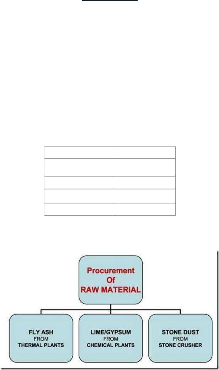
Process of Manufacture:
Fly ash, hydrated lime, Quarry dust and gypsum are manually fed into a pan mixer where water
is added in the required proportion for intimate mixing. The proportion of the raw material is
generally in the ratio depending upon the quality of raw materials. After mixing, the mixture is
shifted to the hydraulic Brick Making machines. The bricks are carried on wooden pellets to the
open area where they are dried and water cured for 14 days. The bricks are tested and sorted
before dispatch
Composition
Ingredient
62%
fly ash
8%
lime
5%
Gypsum
25%
Quarry Dust
Raw Material Procurement

Casting of the Fly ash:

EXPERIMENT 12
PREPARATION OF COVER BLOCKS
AIM: To plaster the wall using the cement mortar and finishing it.
APPARTUS: Cement, Fine Aggregate, Wall
PROCEDURE:
