
Specications are subject to change without notice. © 2019 Mitsubishi Electric Trane HVAC US LLC. All rights reserved.
Job Name:
System Reference: Date:
Main BC Controller: CMB-P108NU-JA1
ACCESSORIES
Branch Joint (Downstream capacity ≤72,000 Btu/h) CMY-Y102SS-G2*
Branch Joint (Downstream capacity 73,000-96,000 Btu/h) CMY-Y102LS-G2*
Branch Joint (Downstream capacity ≤126,000 Btu/h) CMY-R201S-G*
Branch Joint (Downstream capacity 127,000-216,000 Btu/h) CMY-R202S-G*
Branch Joint (Downstream capacity 217,000-234,000 Btu/h) CMY-R203S-G*
Branch Joint (Downstream capacity 235,000-360,000 Btu/h) CMY-R204S-G*
Branch Joint (Downstream capacity ≥316,000 Btu/h CMY-R205S-G*
Condensate Pump (Blue Diamond X87-721
Condensate Pump (Sauermann) SI3100-230
Ball Valve (3/8” SAE Brazed) BV38BBSI
Ball Valve (5/8” SAE Brazed) BV58BBSI
Reducer (Between ODU and BC) CMY-R302S-G1*
Reducer (Between Main and Sub BC) CMY-R303S-G1
*See Data Book or Install Manual for more details
NOTES:
1. Installation/foundation work, electrical connection work, insulation work, power source switch, and other items shall be referred to the Installation Manual.
2. The equipment is for R410A refrigerant.
3. Install this product in a location where noise (refrigerant noise) emitted by the unit will not disturb the neighbors. (For use in quiet environments with low background noise, position the BC CONTROLLER at least
5m away from any indoor units.)
4. Sound pressure/power level differs depending on the connected outdoor/heat source unit capacity or operation condition. The sound pressure/power level at the rated operation is the value of the cooling mode.
5. The sound pressure/power level values were obtained in an anechoic room. Actual sound pressure level is usually greater than that measured in anechoic room due to ambient noise and deection sound.
6. The sound pressure level values were obtained at the location below 1.5m from the unit.
7. The solenoid valve switching sound is 56 dB (sound pressure level) regardless of the unit model.
8. Refrigerant piping diameter for connection of plural indoor units with 1 branch shall be referred to the Installation Manual.
9. This unit is not designed for outside installations.
10. When brazing the pipes, be sure to braze, after covering a wet cloth to the insulation pipes of the units in order to prevent it from burning and shrinking by heat.
11. Indoor unit capacity connectable to 1 branch is changed depending on the indoor unit type and connection method. Please refer to the Installation Manual for more information.
12. For the refrigerant pipe size, refer to Installation Manual of outdoor units/heat source units.
SPECIFICATIONS
Indoor Unit Capacity Connectable to 1 Branch Btu/h 54,000
Number Of Branches 8
Electrical Requirements
Electrical Power Requirements 208 / 230V, 1 phase, 60Hz
Minimum Circuit Ampacity (MCA) A 0.83 / 0.97
Maximum Overcurrent Protection (MOCP) A 15
Power Input (208 / 230V
Cooling
kW
0.137 / 0.176
Heating 0.076 / 0.098
Current Input (208 / 230V)
Cooling
A
0.66 / 0.77
Heating 0.37 / 0.43
External Dimensions In. (mm) 9-7/8 x 35-7/8 x 21-1/2 (250 x 911 x 545)
Net Weight Lbs. (kg) 106 (48)
External nish
Galvanized steel plate (Lower part drain pan:
Pre-coated galvanized sheets + powder coating)
Connectable Outdoor / Heat Source Unit Capacity 72,000 to 336,000
Refrigerant Piping Diameter to Indoor Unit (Brazed)
Liquid Gas
Less than 18,000 Btu/h In. (mm) 1/4 (6.35) 1/2 (12.7)
Greater than 18,000 Btu/h
In. (mm) 3/8 (9.52) 5/8 (15.88)
In. (mm) 3/8 (9.52) 3/4 (19.05)
In. (mm) 3/8 (9.52) 7/8 (22.2)
Refrigerant Piping Diameter to Outdoor Unit (Brazed)
High Pressure Low Pressure
P72 In. (mm) 5/8 (15.88) 3/4 (19.05)
P96 In. (mm) 3/4 (19.05) 7/8 (22.2)
P120 In. (mm) 3/4 (19.05) 7/8 (22.2) or 1-1/8 (28.58)
P144 to P192 In. (mm) 3/4 (19.05) 1-1/8 (28.58)
P216 In. (mm) 7/8 (22.2) or 1-1/8 (28.58) 1-1/8 (28.58)
P240 In. (mm) 7/8 (22.2) or 1-1/8 (28.58) 1-3/8 (34.93)
P264 to P288 In. (mm) 1-1/8 (28.58) 1-3/8 (34.93)
P312 In. (mm) 1-1/8 (28.58) 1-3/8 (34.93) or 1-5/8 (41.28)
P336 In. (mm) 1-1/8 (28.58) 1-5/8 (41.28)
Refrigerant Piping Diameter to other BC Controller (Brazed)
High Pressure Liquid Pipe Low Pressure Pipe
P72 In. (mm) 5/8 (15.88) 3/8 (9.52) 3/4 (19.05)
P73 to P108 In. (mm) 3/4 (19.05) 3/8 (9.52) 7/8 (22.2)
P109 to P126 In. (mm) 3/4 (19.05) 1/2 (12.7) 1-1/8 (28.58)
P127 to P144 In. (mm) 7/8 (22.2) 1/2 (12.7) 1-1/8 (28.58)
P145 to P216 In. (mm) 7/8 (22.2) 5/8 (15.88) 1-1/8 (28.58)
P217 to P234 In. (mm) 1-1/8 (28.58) 5/8 (15.88) 1-1/8 (28.58)
P235 to P288 In. (mm) 1-1/8 (28.58) 3/4 (19.05) 1-3/8 (34.93)
P289 to P360 In. (mm) 1-1/8 (28.58) 3/4 (19.05) 1-5/8 (41.28)
P361 or above In. (mm) 1-3/8 (34.93) 3/4 (19.05) 1-5/8 (41.28)
Field drain pipe size In. (mm) 3/4 NPT
Refrigerant R410A
Sound power level (measured in anechoic room)
Rated operation
dB(A)
68
Defrost 74
Sound pressure level (measured in anechoic room)
Rated operation
dB(A)
50
Defrost 56
□
□
□
□
□
□
□
□
□
□
□
□
□
Model: CMB-P108NU-JA1 - DIMENSIONS
MEES18K054
BC controller
15
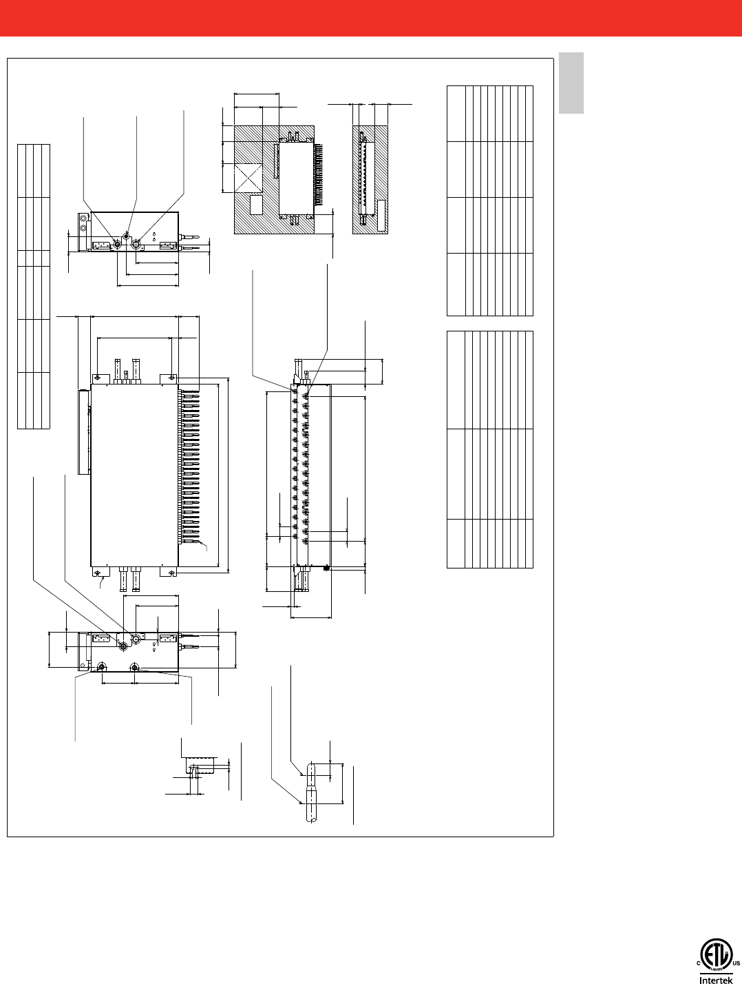
2. EXTERNAL DIMENSIONS
BC controller
CMB-P108, 1012, 1016NU-JA1
Unit: mm(in)
1 2345
6
7 8 9 10 11 12 13 14 15 16
(Lifting bolt pitch)
(Lifting bolt pitch)
ø38.1(1-1/2) (Note 6)
(7-7/16)
(6-1/8)
(15/16) (6-1/4)
(1-7/8)
(3-5/8)
(3-7/8)
(1-7/8)
(1-5/8)
(5-1/8)
(3-1/16)
(6-1/8)
(2-11/16)
(8-13/16)
ø34.93(1-3/8) (Note 6)
Indoor unit model (Note 5)
P18 or less:ø6.35(1/4)<Brazed>
P18 over :ø9.52(3/8)<Brazed>
Indoor unit model (Note 5)
P18 or less:ø12.7(1/2)<Brazed>
P18 over :ø15.88(5/8)<Brazed>
ø28.58(1-1/8) (Note 6)
ø19.05(3/4) (Note 6)
ø38.1(1-1/2) (Note 6)
Control box
(Emergency draining)
Detail of X section
Detail of Y section
(13/16)
(9/16)
(1-3/16)
(1/2)
(Indoor unit Model:P18 over)
(Indoor unit Model:P18 or less)
<Accessories>
•
Square washer (with cushion)
•••••••••
4pcs.
•
Square washer
•••••••••••••••••••••••••••
4pcs.
(10-7/16)
264
(13-1/2)
342
(10-3/4)273
(8-1/16)204
41
(18-1/4)463
(21-1/2)545
77
130
A
B
47
91
47
97
23
155 188
(2-3/8)60
60(2-3/8)×C=D
158
(2-3/8)60
60(2-3/8)×C=D
(9-15/16)
252
(7/8)
22
(3-3/16)80
155
(10-7/16)264
(12-13/16)325
(14-15/16)379
(1)25
68
223
(8-5/8)218
14
12
30
20
(2)50
Y
Connection pipe of outdoor unit
(Low pressure)
Connection pipe of outdoor unit
(High pressure)
Connection pipe of
indoor unit (Liquid)
Connection pipe of
indoor unit (Gas)
Connection pipe of
SUB BC CONTROLLER
(High pressure)
Connection pipe of
SUB BC CONTROLLER
(Liquid)
Connection pipe of
SUB BC CONTROLLER
(Low)
X
3/4 NPT screw
3/4 NPT screw
Cutting point
Cutting point
Note 1. Suspension bolt(ø10) and nut(M10) prepare in the field.
2. Take notice of service space as shown.
(Please give attention not to occupy service
space by letting ducts and pipes through.)
3. Please take service space for connection pipe of SUB BC CONTROLLER.
4. Install this product in a location where noise (refrigerant noise)
emitted by the unit will not disturb the neighbors.
(For use in quiet environments with low background noise, position
the BC CONTROLLER at least 5m away from any indoor units.)
5. Refer to the Installation Manual for refrigerant piping diameter size
when connecting plural indoor units with 1 branch.
6. Refer to the Table-1,2 connection pipe of outdoor unit
or SUB BC CONTROLLER diameter size.
7. Refer to the Installation Manual for insulation of connection pipe and
drain piping.
8. Do not place the BC controller directly on the floor.
Connectable
unit capacity
High press. Pipe Low press. Pipe
P72
ø15.88(5/8)
ø19.05(3/4)
P96
ø19.05(3/4) ø22.2(7/8)
P120
ø19.05(3/4)
ø22.2(7/8) or ø28.58(1-1/8)
P144 to P192
ø22.2(7/8) ø28.58(1-1/8)
P216
ø22.2(7/8) or ø28.58(1-1/8)
ø28.58(1-1/8)
P240
ø22.2(7/8) or ø28.58(1-1/8)
ø34.93(1-3/8)
P264 to P288
ø28.58(1-1/8)
ø34.93(1-3/8)
P312
ø28.58(1-1/8)
ø34.93(1-3/8) or ø41.28(1-5/8)
P336
ø28.58(1-1/8)
ø41.28(1-5/8)
Table-1. To outdoor/heat source unit (Note.6)
Total downstream
Indoor unit capacity
High press. Pipe Liquid Pipe Low press. Pipe
~P72
ø15.88(5/8) ø9.52(3/8) ø19.05(3/4)
P73~108
ø19.05(3/4) ø9.52(3/8) ø22.2(7/8)
P109~126
ø19.05(3/4) ø12.7(1/2) ø28.58(1-1/8)
P127~144
ø22.2(7/8) ø12.7(1/2) ø28.58(1-1/8)
P145~216
ø22.2(7/8) ø15.88(5/8) ø28.58(1-1/8)
P217~234
ø28.58(1-1/8) ø15.88(5/8) ø28.58(1-1/8)
P235~288
ø28.58(1-1/8) ø19.05(3/4) ø34.93(1-3/8)
P289~360
ø28.58(1-1/8) ø19.05(3/4) ø41.28(1-5/8)
P361~
ø34.93(1-3/8) ø19.05(3/4)
ø41.28(1-5/8)
Table-2. To other BC controller (Note.6)
*For the refrigerant pipe size, refer to Installation Manual of outdoor units/heat source units.
*
*
*
*
Access
door
(17-3/4) (9-7/8)
(11-13/16)
(17-3/4)
(9-7/8)
(3-15/16)
(7-7/8)
A BCD E
CMB-P108NU-JA1
911(35-7/8) 983(38-3/4) 7 420(16-9/16) 231(9-1/8)
CMB-P1012NU-JA1
1135(44-11/16) 1207(47-9/16) 11 660(26) 343(13-9/16)
CMB-P1016NU-JA1
1135(44-11/16) 1207(47-9/16) 15 900(35-7/16) 343(13-9/16)
(100)
(200)
250
(27-3/8)(700)
250
(300)
450
E
450
Service space
space
Service
0000005075.BOOK 15 ページ 2018年12月5日 水曜日 午後2時30分
1340 Satellite Boulevard. Suwanee, GA 30024
Toll Free: 800-433-4822 www.mehvac.com
FORM# CMB-P108NU-JA1 Product Data Sheet - 202005
Specications are subject to change without notice.
© 2020 Mitsubishi Electric Trane HVAC US LLC. All rights reserved.
