
CITY MULTI
MEES19K173
2. BC CONTROLLER
GENERAL LINE-UP
BC controller
CMB-M-V-J1(-TR) R32 R410A ...............................................................................................................2 - 1
CMB-M-V-JA1(-TR)
R32 R410A.............................................................................................................2 - 1
CMB-P-V-KA1(-TR)
R410A .......................................................................................................................2 - 1
CMB-M-V-KB1(-TR)
R32 R410A ............................................................................................................2 - 1
MEES19K173
GENERAL LINE-UP
GENERAL LINE-UP
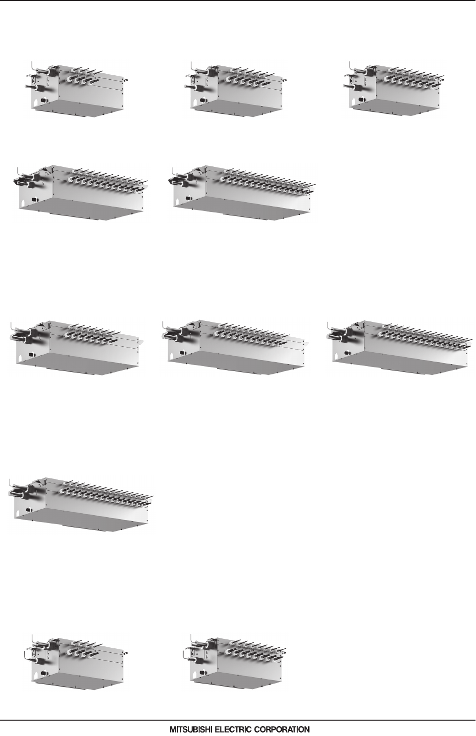
I.GENERAL LINE-UP
Main BC controller (J1 type)
CMB-M104V-J1 (-TR) CMB-M106V-J1 (-TR) CMB-M108V-J1 (-TR)
CMB-M1012V-J1 (-TR)
CMB-M1016V-J1 (-TR)
Main BC controller (JA1 type)
CMB-M108V-JA1 (-TR) CMB-M1012V-JA1 (-TR) CMB-M1016V-JA1 (-TR)
Main BC controller (KA1 type)
CMB-P1016V-KA1 (-TR)
Sub BC controller (KB1 type)
CMB-M104V-KB1 (-TR) CMB-M108V-KB1 (-TR)

CMB-M-V-J1(-TR), CMB-M-V-JA1(-TR), CMB-P-V-KA1(-TR), CMB-M-V-KB1(-TR)
MEES19K085
2 - 1
CONTENTS
BC controller
I.
BC controll er
1. SPECIFICATIONS .................................................................................................................................... 2 - 2
2. EXTERNAL DIMENSIONS ....................................................................................................................... 2 - 13
3. ELECTRICAL WIRING DIAGRAMS ......................................................................................................... 2 - 18
4. SOUND LEVELS ...................................................................................................................................... 2 - 27
4-1. Sound levels in cooling mode .......................................................................................................... 2 - 27
4-2. Sound levels in heating mode.......................................................................................................... 2 - 28
4-3. Sound levels in defrost mode .......................................................................................................... 2 - 29
5. ELECTRICAL CHARACTERISTICS......................................................................................................... 2 - 30
6. OPTIONAL PARTS................................................................................................................................... 2 - 31
6-1. JOINT and REDUCER..................................................................................................................... 2 - 31
6-2. JOINT KIT "CMY-R160-J1" FOR BC CONTROLLER ..................................................................... 2 - 36
7. INSTALLATION ........................................................................................................................................ 2 - 37
7-1. Installing BC controllers ................................................................................................................... 2 - 37
8. SYSTEM DESIGN .................................................................................................................................... 2 - 38
8-1. Compatibility .................................................................................................................................... 2 - 38
8-2. System examples ............................................................................................................................ 2 - 39

MEES19K085
BC controller
2 - 2
1. SPECIFICATIONS
BC controller
I.BC controll er1. SPECIFICATIONS
Model CMB-M104V-J1 (-TR)
Number of branch 4
Power source 1-phase 220-230-240 V
50Hz 60Hz
Power input Cooling kW 0.067/0.076/0.085 0.054/0.061/0.067
Heating kW 0.030/0.034/0.038 0.024/0.027/0.030
Current input Cooling A 0.31/0.34/0.36 0.25/0.27/0.28
Heating A 0.14/0.15/0.16 0.11/0.12/0.13
External finish Galvanized steel plate
(Lower part drain pan: Pre-coated galvanized sheets + powder coating)
Connectable outdoor/heat source unit capacity P200 to P350/M200 to M300
Indoor unit capacity connectable to 1 branch *14
Model P/M80 or smaller
(Use optional joint pipe combining 2 branches when the total unit capacity exceeds P/M81.)
External dimension H x W x D mm 250 x 596 x 476
in. 9-7/8 x 23-1/2 x 18-3/4
Refrigerant To outdoor/heat source unit Connectable unit capacity High press. Pipe Low press. Pipe
piping mm (in.) O.D. P200/M200 15.88 (5/8) Brazed 19.05 (3/4) Brazed
diameter mm (in.) O.D. P250/P300 19.05 (3/4) Brazed 22.2 (7/8) Brazed
*15 mm (in.) O.D. P350
19.05 (3/4) Brazed or 22.2 (7/8)
Brazed
28.58 (1-1/8) Brazed
mm (in.) O.D. M250/M300 15.88 (5/8) Brazed 22.2 (7/8) Brazed
To indoor unit Liquid pipe Gas pipe
mm (in.) O.D.
Indoor unit Model 50 or smaller 6.35 (1/4) Brazed Indoor unit Model 50 or smaller 12.7 (1/2) Brazed
bigger than 50 9.52 (3/8) Brazed bigger than 50 15.88 (5/8) Brazed
(19.05 (3/4), 22.2 (7/8) with optional joint pipe used.)
Field drain pipe size mm (in.) O.D. 32 (1-1/4)
Net weight kg (lbs) 26 (58)
Sound power level
Rated operation dB <A> 59
(measured in anechoic room)
Defrost dB <A> 71
Sound pressure level
Rated operation dB <A> 40
(measured in anechoic room)
*16 Defrost dB <A> 53
Accessories Drain Connection pipe, Washer, Tie band
Remarks
Notes:
1.Installation/foundation work, electrical connection work, insulation work, power source switch, and other items
shall be referred to the Installation Manual.
2.The equipment is for R410A or R32 refrigerant.
3.Install this product in a location where noise (refrigerant noise) emitted by the unit will not disturb the neighbors.
(For use in quiet environments with low background noise, position the BC CONTROLLER at least 5m away
from any indoor units.)
4.Sound pressure/power level differs depending on the connected outdoor/heat source unit capacity or operation condition.
The sound pressure/power level at the rated operation is the value of the cooling mode.
5.The sound pressure/power level values were obtained in an anechoic room. Actual sound pressure level is usually
greater than that measured in anechoic room due to ambient noise and deflection sound.
6.The sound pressure level values were obtained at the location below 1.5m from the unit.
7.The solenoid valve switching sound is 56 dB (sound pressure level) regardless of the unit model.
8.Indoor units P/M100, P/M125, P/M140 can be connected to 1 branch. (In this case, cooling capacity decrease a little.)
9.Refrigerant piping diameter for connection of plural indoor units with 1 branch shall be referred to the
Installation Manual.
10.This unit is not designed for outside installations.
11.When blazing the pipes, be sure to blaze, after covering a wet cloth to the insulation pipes of the units in order to prevent
it from burning and shrinking by heat.
12.The ambient relative humidity of the BC controller needs to be kept below 80%.
13.R32 is flammable, and certain restrictions apply to the installation of units.
When installing new units, moving the existing units, or changing the layout of the room,
ensure that installation restrictions are observed.
For detail, refer to the section in the DATA BOOK on installation restrictions.
14.Indoor unit capacity connectable to 1 branch is changed depending on the indoor unit type and connection
method. Please refer to the Installation Manual for more information.
15.For the refrigerant pipe size, refer to Installation Manual of outdoor units/heat source units.
16.The sound pressure level measured by the conventional method in JIS for reference purpose.

MEES19K085
BC controller
2 - 3
1. SPECIFICATIONS
BC controller
Model CMB-M106V-J1 (-TR)
Number of branch 6
Power source 1-phase 220-230-240 V
50Hz 60Hz
Power input Cooling kW 0.097/0.110/0.123 0.078/0.088/0.097
Heating kW 0.045/0.051/0.057 0.036/0.041/0.045
Current input Cooling A 0.45/0.48/0.52 0.36/0.39/0.41
Heating A 0.21/0.23/0.24 0.17/0.18/0.19
External finish Galvanized steel plate
(Lower part drain pan: Pre-coated galvanized sheets + powder coating)
Connectable outdoor/heat source unit capacity P200 to P350/M200 to M300
Indoor unit capacity connectable to 1 branch *14
Model P/M80 or smaller
(Use optional joint pipe combining 2 branches when the total unit capacity exceeds P/M81.)
External dimension H x W x D mm 250 x 596 x 476
in. 9-7/8 x 23-1/2 x 18-3/4
Refrigerant To outdoor/heat source unit Connectable unit capacity High press. Pipe Low press. Pipe
piping mm (in.) O.D. P200/M200 15.88 (5/8) Brazed 19.05 (3/4) Brazed
diameter mm (in.) O.D. P250/P300 19.05 (3/4) Brazed 22.2 (7/8) Brazed
*15 mm (in.) O.D. P350
19.05 (3/4) Brazed or 22.2 (7/8)
Brazed
28.58 (1-1/8) Brazed
mm (in.) O.D. M250/M300 15.88 (5/8) Brazed 22.2 (7/8) Brazed
To indoor unit Liquid pipe Gas pipe
mm (in.) O.D.
Indoor unit Model 50 or smaller 6.35 (1/4) Brazed Indoor unit Model 50 or smaller 12.7 (1/2) Brazed
bigger than 50 9.52 (3/8) Brazed bigger than 50 15.88 (5/8) Brazed
(19.05 (3/4), 22.2 (7/8) with optional joint pipe used.)
Field drain pipe size mm (in.) O.D. 32 (1-1/4)
Net weight kg (lbs) 29 (64)
Sound power level
Rated operation dB <A> 59
(measured in anechoic room)
Defrost dB <A> 71
Sound pressure level
Rated operation dB <A> 40
(measured in anechoic room)
*16 Defrost dB <A> 53
Accessories Drain Connection pipe, Washer, Tie band
Remarks
Notes:
1.Installation/foundation work, electrical connection work, insulation work, power source switch, and other items
shall be referred to the Installation Manual.
2.The equipment is for R410A or R32 refrigerant.
3.Install this product in a location where noise (refrigerant noise) emitted by the unit will not disturb the neighbors.
(For use in quiet environments with low background noise, position the BC CONTROLLER at least 5m away
from any indoor units.)
4.Sound pressure/power level differs depending on the connected outdoor/heat source unit capacity or operation condition.
The sound pressure/power level at the rated operation is the value of the cooling mode.
5.The sound pressure/power level values were obtained in an anechoic room. Actual sound pressure level is usually
greater than that measured in anechoic room due to ambient noise and deflection sound.
6.The sound pressure level values were obtained at the location below 1.5m from the unit.
7.The solenoid valve switching sound is 56 dB (sound pressure level) regardless of the unit model.
8.Indoor units P/M100, P/M125, P/M140 can be connected to 1 branch. (In this case, cooling capacity decrease a little.)
9.Refrigerant piping diameter for connection of plural indoor units with 1 branch shall be referred to the
Installation Manual.
10.This unit is not designed for outside installations.
11.When blazing the pipes, be sure to blaze, after covering a wet cloth to the insulation pipes of the units in order to prevent
it from burning and shrinking by heat.
12.The ambient relative humidity of the BC controller needs to be kept below 80%.
13.R32 is flammable, and certain restrictions apply to the installation of units.
When installing new units, moving the existing units, or changing the layout of the room,
ensure that installation restrictions are observed.
For detail, refer to the section in the DATA BOOK on installation restrictions.
14.Indoor unit capacity connectable to 1 branch is changed depending on the indoor unit type and connection
method. Please refer to the Installation Manual for more information.
15.For the refrigerant pipe size, refer to Installation Manual of outdoor units/heat source units.
16.The sound pressure level measured by the conventional method in JIS for reference purpose.

MEES19K085
BC controller
2 - 4
1. SPECIFICATIONS
BC controller
Model CMB-M108V-J1 (-TR)
Number of branch 8
Power source 1-phase 220-230-240 V
50Hz 60Hz
Power input Cooling kW 0.127/0.144/0.161 0.102/0.115/0.127
Heating kW 0.060/0.068/0.076 0.048/0.054/0.060
Current input Cooling A 0.58/0.63/0.68 0.47/0.50/0.53
Heating A 0.28/0.30/0.32 0.22/0.24/0.25
External finish Galvanized steel plate
(Lower part drain pan: Pre-coated galvanized sheets + powder coating)
Connectable outdoor/heat source unit capacity P200 to P350/M200 to M300
Indoor unit capacity connectable to 1 branch *14
Model P/M80 or smaller
(Use optional joint pipe combining 2 branches when the total unit capacity exceeds P/M81.)
External dimension H x W x D mm 250 x 596 x 476
in. 9-7/8 x 23-1/2 x 18-3/4
Refrigerant To outdoor/heat source unit Connectable unit capacity High press. Pipe Low press. Pipe
piping mm (in.) O.D. P200/M200 15.88 (5/8) Brazed 19.05 (3/4) Brazed
diameter mm (in.) O.D. P250/P300 19.05 (3/4) Brazed 22.2 (7/8) Brazed
*15 mm (in.) O.D. P350
19.05 (3/4) Brazed or 22.2 (7/8)
Brazed
28.58 (1-1/8) Brazed
mm (in.) O.D. M250/M300 15.88 (5/8) Brazed 22.2 (7/8) Brazed
To indoor unit Liquid pipe Gas pipe
mm (in.) O.D.
Indoor unit Model 50 or smaller 6.35 (1/4) Brazed Indoor unit Model 50 or smaller 12.7 (1/2) Brazed
bigger than 50 9.52 (3/8) Brazed bigger than 50 15.88 (5/8) Brazed
(19.05 (3/4), 22.2 (7/8) with optional joint pipe used.)
Field drain pipe size mm (in.) O.D. 32 (1-1/4)
Net weight kg (lbs) 33 (73)
Sound power level
Rated operation dB <A> 59
(measured in anechoic room)
Defrost dB <A> 71
Sound pressure level
Rated operation dB <A> 40
(measured in anechoic room)
*16 Defrost dB <A> 53
Accessories Drain Connection pipe, Washer, Tie band
Remarks
Notes:
1.Installation/foundation work, electrical connection work, insulation work, power source switch, and other items
shall be referred to the Installation Manual.
2.The equipment is for R410A or R32 refrigerant.
3.Install this product in a location where noise (refrigerant noise) emitted by the unit will not disturb the neighbors.
(For use in quiet environments with low background noise, position the BC CONTROLLER at least 5m away
from any indoor units.)
4.Sound pressure/power level differs depending on the connected outdoor/heat source unit capacity or operation condition.
The sound pressure/power level at the rated operation is the value of the cooling mode.
5.The sound pressure/power level values were obtained in an anechoic room. Actual sound pressure level is usually
greater than that measured in anechoic room due to ambient noise and deflection sound.
6.The sound pressure level values were obtained at the location below 1.5m from the unit.
7.The solenoid valve switching sound is 56 dB (sound pressure level) regardless of the unit model.
8.Indoor units P/M100, P/M125, P/M140 can be connected to 1 branch. (In this case, cooling capacity decrease a little.)
9.Refrigerant piping diameter for connection of plural indoor units with 1 branch shall be referred to the
Installation Manual.
10.This unit is not designed for outside installations.
11.When blazing the pipes, be sure to blaze, after covering a wet cloth to the insulation pipes of the units in order to prevent
it from burning and shrinking by heat.
12.The ambient relative humidity of the BC controller needs to be kept below 80%.
13.R32 is flammable, and certain restrictions apply to the installation of units.
When installing new units, moving the existing units, or changing the layout of the room,
ensure that installation restrictions are observed.
For detail, refer to the section in the DATA BOOK on installation restrictions.
14.Indoor unit capacity connectable to 1 branch is changed depending on the indoor unit type and connection
method. Please refer to the Installation Manual for more information.
15.For the refrigerant pipe size, refer to Installation Manual of outdoor units/heat source units.
16.The sound pressure level measured by the conventional method in JIS for reference purpose.

MEES19K085
BC controller
2 - 5
1. SPECIFICATIONS
BC controller
Model CMB-M1012V-J1 (-TR)
Number of branch 12
Power source 1-phase 220-230-240 V
50Hz 60Hz
Power input Cooling kW 0.186/0.211/0.236 0.150/0.168/0.186
Heating kW 0.090/0.102/0.114 0.072/0.081/0.090
Current input Cooling A 0.85/0.92/0.99 0.69/0.74/0.78
Heating A 0.42/0.44/0.48 0.33/0.36/0.38
External finish Galvanized steel plate
(Lower part drain pan: Pre-coated galvanized sheets + powder coating)
Connectable outdoor/heat source unit capacity P200 to P350/M200 to M300
Indoor unit capacity connectable to 1 branch *14
Model P/M80 or smaller
(Use optional joint pipe combining 2 branches when the total unit capacity exceeds P/M81.)
External dimension H x W x D mm 252 x 911 x 622
in. 9-15/16 x 35-7/8 x 24-1/2
Refrigerant To outdoor/heat source unit Connectable unit capacity High press. Pipe Low press. Pipe
piping mm (in.) O.D. P200/M200 15.88 (5/8) Brazed 19.05 (3/4) Brazed
diameter mm (in.) O.D. P250/P300 19.05 (3/4) Brazed 22.2 (7/8) Brazed
*15 mm (in.) O.D. P350
19.05 (3/4) Brazed or 22.2 (7/8)
Brazed
28.58 (1-1/8) Brazed
mm (in.) O.D. M250/M300 15.88 (5/8) Brazed 22.2 (7/8) Brazed
To indoor unit Liquid pipe Gas pipe
mm (in.) O.D.
Indoor unit Model 50 or smaller 6.35 (1/4) Brazed Indoor unit Model 50 or smaller 12.7 (1/2) Brazed
bigger than 50 9.52 (3/8) Brazed bigger than 50 15.88 (5/8) Brazed
(19.05 (3/4), 22.2 (7/8) with optional joint pipe used.)
Field drain pipe size mm (in.) O.D. 32 (1-1/4)
Net weight kg (lbs) 49 (109)
Sound power level
Rated operation dB <A> 59
(measured in anechoic room)
Defrost dB <A> 71
Sound pressure level
Rated operation dB <A> 40
(measured in anechoic room)
*16 Defrost dB <A> 53
Accessories Drain Connection pipe, Washer, Tie band
Remarks
Notes:
1.Installation/foundation work, electrical connection work, insulation work, power source switch, and other items
shall be referred to the Installation Manual.
2.The equipment is for R410A or R32 refrigerant.
3.Install this product in a location where noise (refrigerant noise) emitted by the unit will not disturb the neighbors.
(For use in quiet environments with low background noise, position the BC CONTROLLER at least 5m away
from any indoor units.)
4.Sound pressure/power level differs depending on the connected outdoor/heat source unit capacity or operation condition.
The sound pressure/power level at the rated operation is the value of the cooling mode.
5.The sound pressure/power level values were obtained in an anechoic room. Actual sound pressure level is usually
greater than that measured in anechoic room due to ambient noise and deflection sound.
6.The sound pressure level values were obtained at the location below 1.5m from the unit.
7.The solenoid valve switching sound is 56 dB (sound pressure level) regardless of the unit model.
8.Indoor units P/M100, P/M125, P/M140 can be connected to 1 branch. (In this case, cooling capacity decrease a little.)
9.Refrigerant piping diameter for connection of plural indoor units with 1 branch shall be referred to the
Installation Manual.
10.This unit is not designed for outside installations.
11.When blazing the pipes, be sure to blaze, after covering a wet cloth to the insulation pipes of the units in order to prevent
it from burning and shrinking by heat.
12.The ambient relative humidity of the BC controller needs to be kept below 80%.
13.R32 is flammable, and certain restrictions apply to the installation of units.
When installing new units, moving the existing units, or changing the layout of the room,
ensure that installation restrictions are observed.
For detail, refer to the section in the DATA BOOK on installation restrictions.
14.Indoor unit capacity connectable to 1 branch is changed depending on the indoor unit type and connection
method. Please refer to the Installation Manual for more information.
15.For the refrigerant pipe size, refer to Installation Manual of outdoor units/heat source units.
16.The sound pressure level measured by the conventional method in JIS for reference purpose.

MEES19K085
BC controller
2 - 6
1. SPECIFICATIONS
BC controller
Model CMB-M1016V-J1 (-TR)
Number of branch 16
Power source 1-phase 220-230-240 V
50Hz 60Hz
Power input Cooling kW 0.246/0.279/0.312 0.198/0.222/0.246
Heating kW 0.119/0.135/0.151 0.096/0.108/0.119
Current input Cooling A 1.12/1.22/1.30 0.90/0.97/1.03
Heating A 0.55/0.59/0.63 0.44/0.47/0.50
External finish Galvanized steel plate
(Lower part drain pan: Pre-coated galvanized sheets + powder coating)
Connectable outdoor/heat source unit capacity P200 to P350/M200 to M300
Indoor unit capacity connectable to 1 branch *14
Model P/M80 or smaller
(Use optional joint pipe combining 2 branches when the total unit capacity exceeds P/M81.)
External dimension H x W x D mm 252 x 1,135 x 622
in. 9-15/16 x 44-11/16 x 24-1/2
Refrigerant To outdoor/heat source unit Connectable unit capacity High press. Pipe Low press. Pipe
piping mm (in.) O.D. P200/M200 15.88 (5/8) Brazed 19.05 (3/4) Brazed
diameter mm (in.) O.D. P250/P300 19.05 (3/4) Brazed 22.2 (7/8) Brazed
*15 mm (in.) O.D. P350
19.05 (3/4) Brazed or 22.2 (7/8)
Brazed
28.58 (1-1/8) Brazed
mm (in.) O.D. M250/M300 15.88 (5/8) Brazed 22.2 (7/8) Brazed
To indoor unit Liquid pipe Gas pipe
mm (in.) O.D.
Indoor unit Model 50 or smaller 6.35 (1/4) Brazed Indoor unit Model 50 or smaller 12.7 (1/2) Brazed
bigger than 50 9.52 (3/8) Brazed bigger than 50 15.88 (5/8) Brazed
(19.05 (3/4), 22.2 (7/8) with optional joint pipe used.)
Field drain pipe size mm (in.) O.D. 32 (1-1/4)
Net weight kg (lbs) 59 (131)
Sound power level
Rated operation dB <A> 59
(measured in anechoic room)
Defrost dB <A> 71
Sound pressure level
Rated operation dB <A> 40
(measured in anechoic room)
*16 Defrost dB <A> 53
Accessories Drain Connection pipe, Washer, Tie band
Remarks
Notes:
1.Installation/foundation work, electrical connection work, insulation work, power source switch, and other items
shall be referred to the Installation Manual.
2.The equipment is for R410A or R32 refrigerant.
3.Install this product in a location where noise (refrigerant noise) emitted by the unit will not disturb the neighbors.
(For use in quiet environments with low background noise, position the BC CONTROLLER at least 5m away
from any indoor units.)
4.Sound pressure/power level differs depending on the connected outdoor/heat source unit capacity or operation condition.
The sound pressure/power level at the rated operation is the value of the cooling mode.
5.The sound pressure/power level values were obtained in an anechoic room. Actual sound pressure level is usually
greater than that measured in anechoic room due to ambient noise and deflection sound.
6.The sound pressure level values were obtained at the location below 1.5m from the unit.
7.The solenoid valve switching sound is 56 dB (sound pressure level) regardless of the unit model.
8.Indoor units P/M100, P/M125, P/M140 can be connected to 1 branch. (In this case, cooling capacity decrease a little.)
9.Refrigerant piping diameter for connection of plural indoor units with 1 branch shall be referred to the
Installation Manual.
10.This unit is not designed for outside installations.
11.When blazing the pipes, be sure to blaze, after covering a wet cloth to the insulation pipes of the units in order to prevent
it from burning and shrinking by heat.
12.The ambient relative humidity of the BC controller needs to be kept below 80%.
13.R32 is flammable, and certain restrictions apply to the installation of units.
When installing new units, moving the existing units, or changing the layout of the room,
ensure that installation restrictions are observed.
For detail, refer to the section in the DATA BOOK on installation restrictions.
14.Indoor unit capacity connectable to 1 branch is changed depending on the indoor unit type and connection
method. Please refer to the Installation Manual for more information.
15.For the refrigerant pipe size, refer to Installation Manual of outdoor units/heat source units.
16.The sound pressure level measured by the conventional method in JIS for reference purpose.

MEES19K085
BC controller
2 - 7
1. SPECIFICATIONS
BC controller
Model CMB-M108V-JA1 (-TR)
Number of branch 8
Power source 1-phase 220-230-240 V
50Hz 60Hz
Power input Cooling kW 0.127/0.144/0.161 0.102/0.115/0.127
Heating kW 0.060/0.068/0.076 0.048/0.054/0.060
Current input Cooling A 0.58/0.63/0.68 0.47/0.50/0.53
Heating A 0.28/0.30/0.32 0.22/0.24/0.25
External finish Galvanized steel plate
(Lower part drain pan: Pre-coated galvanized sheets + powder coating)
Connectable outdoor/heat source unit capacity P200 to P900/M200 to M300
Indoor unit capacity connectable to 1 branch *14
Model P/M80 or smaller
(Use optional joint pipe combining 2 branches when the total unit capacity exceeds P/M81.)
External dimension H x W x D mm 252 x 911 x 622
in. 9-15/16 x 35-7/8 x 24-1/2
Refrigerant To outdoor/heat source unit Connectable unit capacity High press. pipe Low press. pipe
piping mm (in.) O.D. P200/M200 15.88 (5/8) Brazed 19.05 (3/4) Brazed
diameter mm (in.) O.D. P250/P300 19.05 (3/4) Brazed 22.2 (7/8) Brazed
*15 mm (in.) O.D. P350
19.05 (3/4) Brazed or 22.2 (7/8)
Brazed
28.58 (1-1/8) Brazed
mm (in.) O.D. P400 to P500 22.2 (7/8) Brazed 28.58 (1-1/8) Brazed
*15 mm (in.) O.D. P550
22.2 (7/8) Brazed or 28.58 (1-1/8)
Brazed
28.58 (1-1/8) Brazed
*15 mm (in.) O.D. P600
22.2 (7/8) Brazed or 28.58 (1-1/8)
Brazed
28.58 (1-1/8) Brazed or 34.93 (1-3/8)
Brazed
mm (in.) O.D. P650 28.58 (1-1/8) Brazed 28.58 (1-1/8) Brazed
mm (in.) O.D. P700 to P800 28.58 (1-1/8) Brazed 34.93 (1-3/8) Brazed
mm (in.) O.D. P850 to P900 28.58 (1-1/8) Brazed 41.28 (1-5/8) Brazed
mm (in.) O.D. M250/M300 15.88 (5/8) Brazed 22.2 (7/8) Brazed
To indoor unit Liquid pipe Gas pipe
mm (in.) O.D.
Indoor unit Model 50 or smaller 6.35 (1/4) Brazed Indoor unit Model 50 or smaller 12.7 (1/2) Brazed
bigger than 50 9.52 (3/8) Brazed bigger than 50 15.88 (5/8) Brazed
(19.05 (3/4), 22.2 (7/8) with optional joint pipe used.)
To other BC controller
Total down-stream Indoor
unit capacity
High press. pipe Liquid pipe Low press. pipe
mm (in.) O.D. to P200/M200 15.88 (5/8) Brazed 9.52 (3/8) Brazed 19.05 (3/4) Brazed
mm (in.) O.D. P201 to P300 19.05 (3/4) Brazed 9.52 (3/8) Brazed 22.2 (7/8) Brazed
mm (in.) O.D. P301 to P350 19.05 (3/4) Brazed 12.7 (1/2) Brazed 28.58 (1-1/8) Brazed
mm (in.) O.D. P351 to P400 22.2 (7/8) Brazed 12.7 (1/2) Brazed 28.58 (1-1/8) Brazed
mm (in.) O.D. P401 to P600 22.2 (7/8) Brazed 15.88 (5/8) Brazed 28.58 (1-1/8) Brazed
mm (in.) O.D. P601 to P650 28.58 (1-1/8) Brazed 15.88 (5/8) Brazed 28.58 (1-1/8) Brazed
mm (in.) O.D. P651 to P800 28.58 (1-1/8) Brazed 19.05 (3/4) Brazed 34.93 (1-3/8) Brazed
mm (in.) O.D. P801 to P1000 28.58 (1-1/8) Brazed 19.05 (3/4) Brazed 41.28 (1-5/8) Brazed
mm (in.) O.D. P1001 or above 34.93 (1-3/8) Brazed 19.05 (3/4) Brazed 41.28 (1-5/8) Brazed
mm (in.) O.D. M201 to M300 15.88 (5/8) Brazed 9.52 (3/8) Brazed 22.2 (7/8) Brazed
mm (in.) O.D. M301 to M350 15.88 (5/8) Brazed 12.7 (1/2) Brazed 28.58 (1-1/8) Brazed
mm (in.) O.D. M351 to M400 19.05 (3/4) Brazed 12.7 (1/2) Brazed 28.58 (1-1/8) Brazed
mm (in.) O.D. M401 to M450 19.05 (3/4) Brazed 15.88 (5/8) Brazed 28.58 (1-1/8) Brazed
Field drain pipe size mm (in.) O.D. 32 (1-1/4)
Net weight kg (lbs) 48 (106)
Sound power level Rated operation
dB <A> 68
(measured in anechoic room)
Defrost dB <A> 74
Sound pressure level Rated operation
dB <A> 50
(measured in anechoic room)
*16 Defrost dB <A> 56
Accessories Drain Connection pipe, Washer, Tie band
Remarks
Notes:
1.Installation/foundation work, electrical connection work, insulation work, power source switch, and other items
shall be referred to the Installation Manual.
2.The equipment is for R410A or R32 refrigerant.
3.Install this product in a location where noise (refrigerant noise) emitted by the unit will not disturb the neighbors.
(For use in quiet environments with low background noise, position the BC CONTROLLER at least 5m away
from any indoor units.)
4.Sound pressure/power level differs depending on the connected outdoor/heat source unit capacity or operation condition.
The sound pressure/power level at the rated operation is the value of the cooling mode.
5.The sound pressure/power level values were obtained in an anechoic room. Actual sound pressure level is usually
greater than that measured in anechoic room due to ambient noise and deflection sound.
6.The sound pressure level values were obtained at the location below 1.5m from the unit.
7.The solenoid valve switching sound is 56 dB (sound pressure level) regardless of the unit model.
8.Indoor units P/M100, P/M125, P/M140 can be connected to 1 branch. (In this case, cooling capacity decrease a little.)
9.Refrigerant piping diameter for connection of plural indoor units with 1 branch shall be referred to the
Installation Manual.
10.This unit is not designed for outside installations.
11.When blazing the pipes, be sure to blaze, after covering a wet cloth to the insulation pipes of the units in order to prevent
it from burning and shrinking by heat.
12.The ambient relative humidity of the BC controller needs to be kept below 80%.
13.R32 is flammable, and certain restrictions apply to the installation of units.
When installing new units, moving the existing units, or changing the layout of the room,
ensure that installation restrictions are observed.
For detail, refer to the section in the DATA BOOK on installation restrictions.
14.Indoor unit capacity connectable to 1 branch is changed depending on the indoor unit type and connection
method. Please refer to the Installation Manual for more information.
15.For the refrigerant pipe size, refer to Installation Manual of outdoor units/heat source units.
16.The sound pressure level measured by the conventional method in JIS for reference purpose.

MEES19K085
BC controller
2 - 8
1. SPECIFICATIONS
BC controller
Model CMB-M1012V-JA1 (-TR)
Number of branch 12
Power source 1-phase 220-230-240 V
50Hz 60Hz
Power input Cooling kW 0.186/0.211/0.236 0.150/0.168/0.186
Heating kW 0.090/0.102/0.114 0.072/0.081/0.090
Current input Cooling A 0.85/0.92/0.99 0.69/0.74/0.78
Heating A 0.42/0.44/0.48 0.33/0.36/0.38
External finish Galvanized steel plate
(Lower part drain pan: Pre-coated galvanized sheets + powder coating)
Connectable outdoor/heat source unit capacity P200 to P900/M200 to M300
Indoor unit capacity connectable to 1 branch *14
Model P/M80 or smaller
(Use optional joint pipe combining 2 branches when the total unit capacity exceeds P/M81.)
External dimension H x W x D mm 252 x 1,135 x 622
in. 9-15/16 x 44-11/16 x 24-1/2
Refrigerant To outdoor/heat source unit Connectable unit capacity High press. pipe Low press. pipe
piping mm (in.) O.D. P200/M200 15.88 (5/8) Brazed 19.05 (3/4) Brazed
diameter mm (in.) O.D. P250/P300 19.05 (3/4) Brazed 22.2 (7/8) Brazed
*15 mm (in.) O.D. P350
19.05 (3/4) Brazed or 22.2 (7/8)
Brazed
28.58 (1-1/8) Brazed
mm (in.) O.D. P400 to P500 22.2 (7/8) Brazed 28.58 (1-1/8) Brazed
*15 mm (in.) O.D. P550
22.2 (7/8) Brazed or 28.58 (1-1/8)
Brazed
28.58 (1-1/8) Brazed
*15 mm (in.) O.D. P600
22.2 (7/8) Brazed or 28.58 (1-1/8)
Brazed
28.58 (1-1/8) Brazed or 34.93 (1-3/8)
Brazed
mm (in.) O.D. P650 28.58 (1-1/8) Brazed 28.58 (1-1/8) Brazed
mm (in.) O.D. P700 to P800 28.58 (1-1/8) Brazed 34.93 (1-3/8) Brazed
mm (in.) O.D. P850 to P900 28.58 (1-1/8) Brazed 41.28 (1-5/8) Brazed
mm (in.) O.D. M250/M300 15.88 (5/8) Brazed 22.2 (7/8) Brazed
To indoor unit Liquid pipe Gas pipe
mm (in.) O.D.
Indoor unit Model 50 or smaller 6.35 (1/4) Brazed Indoor unit Model 50 or smaller 12.7 (1/2) Brazed
bigger than 50 9.52 (3/8) Brazed bigger than 50 15.88 (5/8) Brazed
(19.05 (3/4), 22.2 (7/8) with optional joint pipe used.)
To other BC controller
Total down-stream Indoor
unit capacity
High press. pipe Liquid pipe Low press. pipe
mm (in.) O.D. to P200/M200 15.88 (5/8) Brazed 9.52 (3/8) Brazed 19.05 (3/4) Brazed
mm (in.) O.D. P201 to P300 19.05 (3/4) Brazed 9.52 (3/8) Brazed 22.2 (7/8) Brazed
mm (in.) O.D. P301 to P350 19.05 (3/4) Brazed 12.7 (1/2) Brazed 28.58 (1-1/8) Brazed
mm (in.) O.D. P351 to P400 22.2 (7/8) Brazed 12.7 (1/2) Brazed 28.58 (1-1/8) Brazed
mm (in.) O.D. P401 to P600 22.2 (7/8) Brazed 15.88 (5/8) Brazed 28.58 (1-1/8) Brazed
mm (in.) O.D. P601 to P650 28.58 (1-1/8) Brazed 15.88 (5/8) Brazed 28.58 (1-1/8) Brazed
mm (in.) O.D. P651 to P800 28.58 (1-1/8) Brazed 19.05 (3/4) Brazed 34.93 (1-3/8) Brazed
mm (in.) O.D. P801 to P1000 28.58 (1-1/8) Brazed 19.05 (3/4) Brazed 41.28 (1-5/8) Brazed
mm (in.) O.D. P1001 or above 34.93 (1-3/8) Brazed 19.05 (3/4) Brazed 41.28 (1-5/8) Brazed
mm (in.) O.D. M201 to M300 15.88 (5/8) Brazed 9.52 (3/8) Brazed 22.2 (7/8) Brazed
mm (in.) O.D. M301 to M350 15.88 (5/8) Brazed 12.7 (1/2) Brazed 28.58 (1-1/8) Brazed
mm (in.) O.D. M351 to M400 19.05 (3/4) Brazed 12.7 (1/2) Brazed 28.58 (1-1/8) Brazed
mm (in.) O.D. M401 to M450 19.05 (3/4) Brazed 15.88 (5/8) Brazed 28.58 (1-1/8) Brazed
Field drain pipe size mm (in.) O.D. 32 (1-1/4)
Net weight kg (lbs) 60 (133)
Sound power level Rated operation
dB <A> 68
(measured in anechoic room)
Defrost dB <A> 74
Sound pressure level Rated operation
dB <A> 50
(measured in anechoic room)
*16 Defrost dB <A> 56
Accessories Drain Connection pipe, Washer, Tie band
Remarks
Notes:
1.Installation/foundation work, electrical connection work, insulation work, power source switch, and other items
shall be referred to the Installation Manual.
2.The equipment is for R410A or R32 refrigerant.
3.Install this product in a location where noise (refrigerant noise) emitted by the unit will not disturb the neighbors.
(For use in quiet environments with low background noise, position the BC CONTROLLER at least 5m away
from any indoor units.)
4.Sound pressure/power level differs depending on the connected outdoor/heat source unit capacity or operation condition.
The sound pressure/power level at the rated operation is the value of the cooling mode.
5.The sound pressure/power level values were obtained in an anechoic room. Actual sound pressure level is usually
greater than that measured in anechoic room due to ambient noise and deflection sound.
6.The sound pressure level values were obtained at the location below 1.5m from the unit.
7.The solenoid valve switching sound is 56 dB (sound pressure level) regardless of the unit model.
8.Indoor units P/M100, P/M125, P/M140 can be connected to 1 branch. (In this case, cooling capacity decrease a little.)
9.Refrigerant piping diameter for connection of plural indoor units with 1 branch shall be referred to the
Installation Manual.
10.This unit is not designed for outside installations.
11.When blazing the pipes, be sure to blaze, after covering a wet cloth to the insulation pipes of the units in order to prevent
it from burning and shrinking by heat.
12.The ambient relative humidity of the BC controller needs to be kept below 80%.
13.R32 is flammable, and certain restrictions apply to the installation of units.
When installing new units, moving the existing units, or changing the layout of the room,
ensure that installation restrictions are observed.
For detail, refer to the section in the DATA BOOK on installation restrictions.
14.Indoor unit capacity connectable to 1 branch is changed depending on the indoor unit type and connection
method. Please refer to the Installation Manual for more information.
15.For the refrigerant pipe size, refer to Installation Manual of outdoor units/heat source units.
16.The sound pressure level measured by the conventional method in JIS for reference purpose.

MEES19K085
BC controller
2 - 9
1. SPECIFICATIONS
BC controller
Model CMB-M1016V-JA1 (-TR)
Number of branch 16
Power source 1-phase 220-230-240 V
50Hz 60Hz
Power input Cooling kW 0.246/0.279/0.312 0.198/0.222/0.246
Heating kW 0.119/0.135/0.151 0.096/0.108/0.119
Current input Cooling A 1.12/1.22/1.30 0.90/0.97/1.03
Heating A 0.55/0.59/0.63 0.44/0.47/0.50
External finish Galvanized steel plate
(Lower part drain pan: Pre-coated galvanized sheets + powder coating)
Connectable outdoor/heat source unit capacity P200 to P900/M200 to M300
Indoor unit capacity connectable to 1 branch *14
Model P/M80 or smaller
(Use optional joint pipe combining 2 branches when the total unit capacity exceeds P/M81.)
External dimension H x W x D mm 252 x 1,135 x 622
in. 9-15/16 x 44-11/16 x 24-1/2
Refrigerant To outdoor/heat source unit Connectable unit capacity High press. pipe Low press. pipe
piping mm (in.) O.D. P200/M200 15.88 (5/8) Brazed 19.05 (3/4) Brazed
diameter mm (in.) O.D. P250/P300 19.05 (3/4) Brazed 22.2 (7/8) Brazed
*15 mm (in.) O.D. P350
19.05 (3/4) Brazed or 22.2 (7/8)
Brazed
28.58 (1-1/8) Brazed
mm (in.) O.D. P400 to P500 22.2 (7/8) Brazed 28.58 (1-1/8) Brazed
*15 mm (in.) O.D. P550
22.2 (7/8) Brazed or 28.58 (1-1/8)
Brazed
28.58 (1-1/8) Brazed
*15 mm (in.) O.D. P600
22.2 (7/8) Brazed or 28.58 (1-1/8)
Brazed
28.58 (1-1/8) Brazed or 34.93 (1-3/8)
Brazed
mm (in.) O.D. P650 28.58 (1-1/8) Brazed 28.58 (1-1/8) Brazed
mm (in.) O.D. P700 to P800 28.58 (1-1/8) Brazed 34.93 (1-3/8) Brazed
mm (in.) O.D. P850 to P900 28.58 (1-1/8) Brazed 41.28 (1-5/8) Brazed
mm (in.) O.D. M250/M300 15.88 (5/8) Brazed 22.2 (7/8) Brazed
To indoor unit Liquid pipe Gas pipe
mm (in.) O.D.
Indoor unit Model 50 or smaller 6.35 (1/4) Brazed Indoor unit Model 50 or smaller 12.7 (1/2) Brazed
bigger than 50 9.52 (3/8) Brazed bigger than 50 15.88 (5/8) Brazed
(19.05 (3/4), 22.2 (7/8) with optional joint pipe used.)
To other BC controller
Total down-stream Indoor
unit capacity
High press. pipe Liquid pipe Low press. pipe
mm (in.) O.D. to P200/M200 15.88 (5/8) Brazed 9.52 (3/8) Brazed 19.05 (3/4) Brazed
mm (in.) O.D. P201 to P300 19.05 (3/4) Brazed 9.52 (3/8) Brazed 22.2 (7/8) Brazed
mm (in.) O.D. P301 to P350 19.05 (3/4) Brazed 12.7 (1/2) Brazed 28.58 (1-1/8) Brazed
mm (in.) O.D. P351 to P400 22.2 (7/8) Brazed 12.7 (1/2) Brazed 28.58 (1-1/8) Brazed
mm (in.) O.D. P401 to P600 22.2 (7/8) Brazed 15.88 (5/8) Brazed 28.58 (1-1/8) Brazed
mm (in.) O.D. P601 to P650 28.58 (1-1/8) Brazed 15.88 (5/8) Brazed 28.58 (1-1/8) Brazed
mm (in.) O.D. P651 to P800 28.58 (1-1/8) Brazed 19.05 (3/4) Brazed 34.93 (1-3/8) Brazed
mm (in.) O.D. P801 to P1000 28.58 (1-1/8) Brazed 19.05 (3/4) Brazed 41.28 (1-5/8) Brazed
mm (in.) O.D. P1001 or above 34.93 (1-3/8) Brazed 19.05 (3/4) Brazed 41.28 (1-5/8) Brazed
mm (in.) O.D. M201 to M300 15.88 (5/8) Brazed 9.52 (3/8) Brazed 22.2 (7/8) Brazed
mm (in.) O.D. M301 to M350 15.88 (5/8) Brazed 12.7 (1/2) Brazed 28.58 (1-1/8) Brazed
mm (in.) O.D. M351 to M400 19.05 (3/4) Brazed 12.7 (1/2) Brazed 28.58 (1-1/8) Brazed
mm (in.) O.D. M401 to M450 19.05 (3/4) Brazed 15.88 (5/8) Brazed 28.58 (1-1/8) Brazed
Field drain pipe size mm (in.) O.D. 32 (1-1/4)
Net weight kg (lbs) 68 (150)
Sound power level Rated operation
dB <A> 68
(measured in anechoic room)
Defrost dB <A> 74
Sound pressure level Rated operation
dB <A> 50
(measured in anechoic room)
*16 Defrost dB <A> 56
Accessories Drain Connection pipe, Washer, Tie band
Remarks
Notes:
1.Installation/foundation work, electrical connection work, insulation work, power source switch, and other items
shall be referred to the Installation Manual.
2.The equipment is for R410A or R32 refrigerant.
3.Install this product in a location where noise (refrigerant noise) emitted by the unit will not disturb the neighbors.
(For use in quiet environments with low background noise, position the BC CONTROLLER at least 5m away
from any indoor units.)
4.Sound pressure/power level differs depending on the connected outdoor/heat source unit capacity or operation condition.
The sound pressure/power level at the rated operation is the value of the cooling mode.
5.The sound pressure/power level values were obtained in an anechoic room. Actual sound pressure level is usually
greater than that measured in anechoic room due to ambient noise and deflection sound.
6.The sound pressure level values were obtained at the location below 1.5m from the unit.
7.The solenoid valve switching sound is 56 dB (sound pressure level) regardless of the unit model.
8.Indoor units P/M100, P/M125, P/M140 can be connected to 1 branch. (In this case, cooling capacity decrease a little.)
9.Refrigerant piping diameter for connection of plural indoor units with 1 branch shall be referred to the
Installation Manual.
10.This unit is not designed for outside installations.
11.When blazing the pipes, be sure to blaze, after covering a wet cloth to the insulation pipes of the units in order to prevent
it from burning and shrinking by heat.
12.The ambient relative humidity of the BC controller needs to be kept below 80%.
13.R32 is flammable, and certain restrictions apply to the installation of units.
When installing new units, moving the existing units, or changing the layout of the room,
ensure that installation restrictions are observed.
For detail, refer to the section in the DATA BOOK on installation restrictions.
14.Indoor unit capacity connectable to 1 branch is changed depending on the indoor unit type and connection
method. Please refer to the Installation Manual for more information.
15.For the refrigerant pipe size, refer to Installation Manual of outdoor units/heat source units.
16.The sound pressure level measured by the conventional method in JIS for reference purpose.

MEES19K085
BC controller
2 - 10
1. SPECIFICATIONS
BC controller
Model CMB-P1016V-KA1 (-TR)
Number of branch 16
Power source 1-phase 220-230-240 V
50Hz 60Hz
Power input Cooling kW 0.246/0.279/0.312 0.198/0.222/0.246
Heating kW 0.119/0.135/0.151 0.096/0.108/0.119
Current input Cooling A 1.12/1.22/1.30 0.90/0.97/1.03
Heating A 0.55/0.59/0.63 0.44/0.47/0.50
External finish Galvanized steel plate
(Lower part drain pan: Pre-coated galvanized sheets + powder coating)
Connectable outdoor/heat source unit capacity P200 to P1100
Indoor unit capacity connectable to 1 branch *13
Model P80 or smaller
(Use optional joint pipe combining 2 branches when the total unit capacity exceeds P81.)
External dimension H x W x D mm 250 x 1,135 x 622
in. 9-7/8 x 44-11/16 x 24-1/2
Refrigerant To outdoor/heat source unit Connectable unit capacity High press. pipe Low press. Pipe
piping mm (in.) O.D. P200 15.88 (5/8) Brazed 19.05 (3/4) Brazed
diameter mm (in.) O.D. P250/P300 19.05 (3/4) Brazed 22.2 (7/8) Brazed
*14 mm (in.) O.D. P350
19.05 (3/4) Brazed or 22.2 (7/8)
Brazed
28.58 (1-1/8) Brazed
mm (in.) O.D. P400 to P500 22.2 (7/8) Brazed 28.58 (1-1/8) Brazed
*14 mm (in.) O.D. P550
22.2 (7/8) Brazed or 28.58 (1-1/8)
Brazed
28.58 (1-1/8) Brazed
*14 mm (in.) O.D. P600
22.2 (7/8) Brazed or 28.58 (1-1/8)
Brazed
28.58 (1-1/8) Brazed or 34.93 (1-3/8)
Brazed
mm (in.) O.D. P650 28.58 (1-1/8) Brazed 28.58 (1-1/8) Brazed
mm (in.) O.D. P700 to P800 28.58 (1-1/8) Brazed 34.93 (1-3/8) Brazed
mm (in.) O.D. P850 to P1000 28.58 (1-1/8) Brazed 41.28 (1-5/8) Brazed
mm (in.) O.D. P1050 to P1100 34.93 (1-3/8) Brazed 41.28 (1-5/8) Brazed
To indoor unit Liquid pipe Gas pipe
mm (in.) O.D.
Indoor unit Model 50 or smaller 6.35 (1/4) Brazed Indoor unit Model 50 or smaller 12.7 (1/2) Brazed
bigger than 50 9.52 (3/8) Brazed bigger than 50 15.88 (5/8) Brazed
(19.05 (3/4), 22.2 (7/8) with optional joint pipe used.)
To other BC controller
Total down-stream Indoor
unit capacity
High press. pipe Liquid pipe Low press. pipe
mm (in.) O.D. to P200 15.88 (5/8) Brazed 9.52 (3/8) Brazed 19.05 (3/4) Brazed
mm (in.) O.D. P201 to P300 19.05 (3/4) Brazed 9.52 (3/8) Brazed 22.2 (7/8) Brazed
mm (in.) O.D. P301 to P350 19.05 (3/4) Brazed 12.7 (1/2) Brazed 28.58 (1-1/8) Brazed
mm (in.) O.D. P351 to P400 22.2 (7/8) Brazed 12.7 (1/2) Brazed 28.58 (1-1/8) Brazed
mm (in.) O.D. P401 to P600 22.2 (7/8) Brazed 15.88 (5/8) Brazed 28.58 (1-1/8) Brazed
mm (in.) O.D. P601 to P650 28.58 (1-1/8) Brazed 15.88 (5/8) Brazed 28.58 (1-1/8) Brazed
mm (in.) O.D. P651 to P800 28.58 (1-1/8) Brazed 19.05 (3/4) Brazed 34.93 (1-3/8) Brazed
mm (in.) O.D. P801 to P1000 28.58 (1-1/8) Brazed 19.05 (3/4) Brazed 41.28 (1-5/8) Brazed
mm (in.) O.D. P1001 or above 34.93 (1-3/8) Brazed 19.05 (3/4) Brazed 41.28 (1-5/8) Brazed
Field drain pipe size mm (in.) O.D. 32 (1-1/4)
Net weight kg (lbs) 69 (153)
Sound power level Rated operation
dB <A> 66 (measured in anechoic room)
Defrost dB <A> 73
Sound pressure level Rated operation
dB <A> 48 (measured in anechoic room)
*15 Defrost dB <A> 55
Accessories Drain Connection pipe, Washer, Tie band
Remarks
Notes:
1.Installation/foundation work, electrical connection work, insulation work, power source switch, and other items
shall be referred to the Installation Manual.
2.The equipment is for R410A refrigerant.
3.Install this product in a location where noise (refrigerant noise) emitted by the unit will not disturb the neighbors.
(For use in quiet environments with low background noise, position the BC CONTROLLER at least 5m away
from any indoor units.)
4.Sound pressure/power level differs depending on the connected outdoor/heat source unit capacity or operation condition.
The sound pressure/power level at the rated operation is the value of the cooling mode.
5.The sound pressure/power level values were obtained in an anechoic room. Actual sound pressure level is usually
greater than that measured in anechoic room due to ambient noise and deflection sound.
6.The sound pressure level values were obtained at the location below 1.5m from the unit.
7.The solenoid valve switching sound is 56 dB (sound pressure level) regardless of the unit model.
8.Indoor units P100, P125, P140 can be connected to 1 branch. (In this case, cooling capacity decrease a little.)
9.Refrigerant piping diameter for connection of plural indoor units with 1 branch shall be referred to the
Installation Manual.
10.This unit is not designed for outside installations.
11.When blazing the pipes, be sure to blaze, after covering a wet cloth to the insulation pipes of the units in order to prevent
it from burning and shrinking by heat.
12.The ambient relative humidity of the BC controller needs to be kept below 80%.
13.Indoor unit capacity connectable to 1 branch is changed depending on the indoor unit type and connection
method. Please refer to the Installation Manual for more information.
14.For the refrigerant pipe size, refer to Installation Manual of outdoor units/heat source units.
15.The sound pressure level measured by the conventional method in JIS for reference purpose.

MEES19K085
BC controller
2 - 11
1. SPECIFICATIONS
BC controller
Model CMB-M104V-KB1 (-TR)
Number of branch 4
Power source 1-phase 220-230-240 V
50Hz 60Hz
Power input Cooling kW 0.060/0.068/0.076 0.048/0.054/0.060
Heating kW 0.030/0.034/0.038 0.024/0.027/0.030
Current input Cooling A 0.28/0.30/0.32 0.22/0.24/0.25
Heating A 0.14/0.15/0.16 0.11/0.12/0.13
External finish Galvanized steel plate
(Lower part drain pan: Pre-coated galvanized sheets + powder coating)
Connectable Main BC controller CMB-M108/1012/1016V-JA1 (-TR), CMB-P1016V-KA1 (-TR)
The maximum number of connectable Sub BC controllers 11
The maximum connectable capacity of indoor units P/M350 for each
External dimension H x W x D mm 250 x 596 x 476
in. 9-7/8 x 23-1/2 x 18-3/4
Refrigerant To outdoor/heat source unit Connectable unit capacity High press. pipe Low press. pipe
piping mm (in.) O.D. - - -
diameter To indoor unit Liquid pipe Gas pipe
mm (in.) O.D.
Indoor unit Model 50 or smaller 6.35 (1/4) Brazed Indoor unit Model 50 or smaller 12.7 (1/2) Brazed
bigger than 50 9.52 (3/8) Brazed bigger than 50 15.88 (5/8) Brazed
(19.05 (3/4), 22.2 (7/8) with optional joint pipe used.)
To other BC controller
Total down-stream Indoor
unit capacity
High press. pipe Liquid pipe Low press. pipe
mm (in.) O.D. to P200/M200 15.88 (5/8) Brazed 9.52 (3/8) Brazed 19.05 (3/4) Brazed
mm (in.) O.D. P201 to P300 19.05 (3/4) Brazed 9.52 (3/8) Brazed 22.2 (7/8) Brazed
mm (in.) O.D. P301 to P350 19.05 (3/4) Brazed 12.7 (1/2) Brazed 28.58 (1-1/8) Brazed
mm (in.) O.D. P351 to P400 22.2 (7/8) Brazed 12.7 (1/2) Brazed 28.58 (1-1/8) Brazed
mm (in.) O.D. P401 to P600 22.2 (7/8) Brazed 15.88 (5/8) Brazed 28.58 (1-1/8) Brazed
mm (in.) O.D. P601 to P650 28.58 (1-1/8) Brazed 15.88 (5/8) Brazed 28.58 (1-1/8) Brazed
mm (in.) O.D. P651 to P800 28.58 (1-1/8) Brazed 19.05 (3/4) Brazed 34.93 (1-3/8) Brazed
mm (in.) O.D. P801 to P1000 28.58 (1-1/8) Brazed 19.05 (3/4) Brazed 41.28 (1-5/8) Brazed
mm (in.) O.D. P1001 or above 34.93 (1-3/8) Brazed 19.05 (3/4) Brazed 41.28 (1-5/8) Brazed
mm (in.) O.D. M201 to M300 15.88 (5/8) Brazed 9.52 (3/8) Brazed 22.2 (7/8) Brazed
mm (in.) O.D. M301 to M350 15.88 (5/8) Brazed 12.7 (1/2) Brazed 28.58 (1-1/8) Brazed
mm (in.) O.D. M351 to M400 19.05 (3/4) Brazed 12.7 (1/2) Brazed 28.58 (1-1/8) Brazed
mm (in.) O.D. M401 to M450 19.05 (3/4) Brazed 15.88 (5/8) Brazed 28.58 (1-1/8) Brazed
Field drain pipe size mm (in.) O.D. 32 (1-1/4)
Net weight kg (lbs) 23 (51)
Sound power level Rated operation
dB <A> 59 (measured in anechoic room)
Defrost dB <A> 71
Sound pressure level Rated operation
dB <A> 40 (measured in anechoic room)
*15 Defrost dB <A> 53
Accessories Drain Connection pipe, Washer, Tie band
Remarks
Notes:
1.Installation/foundation work, electrical connection work, insulation work, power source switch, and other items
shall be referred to the Installation Manual.
2.The equipment is for R410A or R32 refrigerant.
3.Install this product in a location where noise (refrigerant noise) emitted by the unit will not disturb the neighbors.
(For use in quiet environments with low background noise, position the BC CONTROLLER at least 5m away
from any indoor units.)
4.Sound pressure/power level differs depending on the connected outdoor/heat source unit capacity or operation condition.
The sound pressure/power level at the rated operation is the value of the cooling mode.
5.The sound pressure/power level values were obtained in an anechoic room. Actual sound pressure level is usually
greater than that measured in anechoic room due to ambient noise and deflection sound.
6.The sound pressure level values were obtained at the location below 1.5m from the unit.
7.The solenoid valve switching sound is 56 dB (sound pressure level) regardless of the unit model.
8.Indoor units P/M100, P/M125, P/M140 can be connected to 1 branch. (In this case, cooling capacity decrease a little.)
9.Refrigerant piping diameter for connection of plural indoor units with 1 branch shall be referred to the
Installation Manual.
10.This unit is not designed for outside installations.
11.When blazing the pipes, be sure to blaze, after covering a wet cloth to the insulation pipes of the units in order to prevent
it from burning and shrinking by heat.
12.Can't use singleness. (MAIN BC CONTROLLER is necessary)
13.The ambient relative humidity of the BC controller needs to be kept below 80%.
14.R32 is flammable, and certain restrictions apply to the installation of units.
When installing new units, moving the existing units, or changing the layout of the room,
ensure that installation restrictions are observed.
For detail, refer to the section in the DATA BOOK on installation restrictions.
15.The sound pressure level measured by the conventional method in JIS for reference purpose.

MEES19K085
BC controller
2 - 12
1. SPECIFICATIONS
BC controller
Model CMB-M108V-KB1 (-TR)
Number of branch 8
Power source 1-phase 220-230-240 V
50Hz 60Hz
Power input Cooling kW 0.119/0.135/0.151 0.096/0.108/0.119
Heating kW 0.060/0.068/0.076 0.048/0.054/0.060
Current input Cooling A 0.55/0.59/0.63 0.44/0.47/0.50
Heating A 0.28/0.30/0.32 0.22/0.24/0.25
External finish Galvanized steel plate
(Lower part drain pan: Pre-coated galvanized sheets + powder coating)
Connectable Main BC controller CMB-M108/1012/1016V-JA1 (-TR), CMB-P1016V-KA1 (-TR)
The maximum number of connectable Sub BC controllers 11
The maximum connectable capacity of indoor units P/M350 for each
External dimension H x W x D mm 250 x 596 x 476
in. 9-7/8 x 23-1/2 x 18-3/4
Refrigerant To outdoor/heat source unit Connectable unit capacity High press. pipe Low press. pipe
piping mm (in.) O.D. - - -
diameter To indoor unit Liquid pipe Gas pipe
mm (in.) O.D.
Indoor unit Model 50 or smaller 6.35 (1/4) Brazed Indoor unit Model 50 or smaller 12.7 (1/2) Brazed
bigger than 50 9.52 (3/8) Brazed bigger than 50 15.88 (5/8) Brazed
(19.05 (3/4), 22.2 (7/8) with optional joint pipe used.)
To other BC controller
Total down-stream Indoor
unit capacity
High press. pipe Liquid pipe Low press. pipe
mm (in.) O.D. to P200/M200 15.88 (5/8) Brazed 9.52 (3/8) Brazed 19.05 (3/4) Brazed
mm (in.) O.D. P201 to P300 19.05 (3/4) Brazed 9.52 (3/8) Brazed 22.2 (7/8) Brazed
mm (in.) O.D. P301 to P350 19.05 (3/4) Brazed 12.7 (1/2) Brazed 28.58 (1-1/8) Brazed
mm (in.) O.D. P351 to P400 22.2 (7/8) Brazed 12.7 (1/2) Brazed 28.58 (1-1/8) Brazed
mm (in.) O.D. P401 to P600 22.2 (7/8) Brazed 15.88 (5/8) Brazed 28.58 (1-1/8) Brazed
mm (in.) O.D. P601 to P650 28.58 (1-1/8) Brazed 15.88 (5/8) Brazed 28.58 (1-1/8) Brazed
mm (in.) O.D. P651 to P800 28.58 (1-1/8) Brazed 19.05 (3/4) Brazed 34.93 (1-3/8) Brazed
mm (in.) O.D. P801 to P1000 28.58 (1-1/8) Brazed 19.05 (3/4) Brazed 41.28 (1-5/8) Brazed
mm (in.) O.D. P1001 or above 34.93 (1-3/8) Brazed 19.05 (3/4) Brazed 41.28 (1-5/8) Brazed
mm (in.) O.D. M201 to M300 15.88 (5/8) Brazed 9.52 (3/8) Brazed 22.2 (7/8) Brazed
mm (in.) O.D. M301 to M350 15.88 (5/8) Brazed 12.7 (1/2) Brazed 28.58 (1-1/8) Brazed
mm (in.) O.D. M351 to M400 19.05 (3/4) Brazed 12.7 (1/2) Brazed 28.58 (1-1/8) Brazed
mm (in.) O.D. M401 to M450 19.05 (3/4) Brazed 15.88 (5/8) Brazed 28.58 (1-1/8) Brazed
Field drain pipe size mm (in.) O.D. 32 (1-1/4)
Net weight kg (lbs) 31 (69)
Sound power level Rated operation
dB <A> 59 (measured in anechoic room)
Defrost dB <A> 71
Sound pressure level Rated operation
dB <A> 40 (measured in anechoic room)
*15 Defrost dB <A> 53
Accessories Drain Connection pipe, Washer, Tie band
Remarks
Notes:
1.Installation/foundation work, electrical connection work, insulation work, power source switch, and other items
shall be referred to the Installation Manual.
2.The equipment is for R410A or R32 refrigerant.
3.Install this product in a location where noise (refrigerant noise) emitted by the unit will not disturb the neighbors.
(For use in quiet environments with low background noise, position the BC CONTROLLER at least 5m away
from any indoor units.)
4.Sound pressure/power level differs depending on the connected outdoor/heat source unit capacity or operation condition.
The sound pressure/power level at the rated operation is the value of the cooling mode.
5.The sound pressure/power level values were obtained in an anechoic room. Actual sound pressure level is usually
greater than that measured in anechoic room due to ambient noise and deflection sound.
6.The sound pressure level values were obtained at the location below 1.5m from the unit.
7.The solenoid valve switching sound is 56 dB (sound pressure level) regardless of the unit model.
8.Indoor units P/M100, P/M125, P/M140 can be connected to 1 branch. (In this case, cooling capacity decrease a little.)
9.Refrigerant piping diameter for connection of plural indoor units with 1 branch shall be referred to the
Installation Manual.
10.This unit is not designed for outside installations.
11.When blazing the pipes, be sure to blaze, after covering a wet cloth to the insulation pipes of the units in order to prevent
it from burning and shrinking by heat.
12.Can't use singleness. (MAIN BC CONTROLLER is necessary)
13.The ambient relative humidity of the BC controller needs to be kept below 80%.
14.R32 is flammable, and certain restrictions apply to the installation of units.
When installing new units, moving the existing units, or changing the layout of the room,
ensure that installation restrictions are observed.
For detail, refer to the section in the DATA BOOK on installation restrictions.
15.The sound pressure level measured by the conventional method in JIS for reference purpose.

MEES19K085
BC controller
2 - 13
2. EXTERNAL DIMENSIONS
BC controller
2. EXTERNAL DIMENSIONS
CMB-M104, 106, 108V-J1(-TR)
Unit: mm
Service
space
Service
space
Control box
(Lifting bolt pitch)
(Lifting bolt pitch)
8
7
6
5
4
3
2
1
Indoor unit model (Note 4)
P/M50 or less:ø6.35<Brazed>
P/M50 over :ø9.52<Brazed>
Indoor unit model (Note 4)
P/M50 or less:ø12.7<Brazed>
P/M50 over :ø15.88<Brazed>
ø19.05 (Note 5)
ø28.58 (Note 5)
(Note 2)
Access
door
Detail of X section
Detail of Y section
(Indoor unit Model:P/M50 over)
(Indoor unit Model:P/M50 or less)
Drain Piping
Note 1. Suspension bolt(ø10) and nut(M10) prepare in the field.
2. Take notice of service space as shown.
(Please give attention not to occupy service space by letting ducts
and pipes through.)
3. Install this product in a location where noise (refrigerant noise)
emitted by the unit will not disturb the neighbors.
(For use in quiet environments with low background noise,position
the BC CONTROLLER at least 5m away from any indoor units.)
4. Refer to the Installation Manual for refrigerant piping diameter size
when connecting plural indoor units with 1 branch.
5. Refer to the Table-1 for connection pipe of outdoor unit diameter
size.
6. Refer to the Installation Manual for insulation of connection pipe and
drain piping.
7. Do not place the BC controller directly on the floor.
<Accessories>
· Drain hose I.D.32 ···························· 1pc.
· Tie band ········································ 3pcs.
· Square washer (with cushion) ············ 4pcs.
· Square washer ······························· 4pcs.
AB
CMB-M104V-J1(-TR)
3180
CMB-M106V-J1(-TR)
5300
CMB-M108V-J1(-TR)
7420
35
78
130
25
199
121
60×A=B118
60
60×A=B
60
88
120
11
68
38
101
596
648
323
398
267
250
221
20
450
250
(250)
(100)
(200)
450
73
(700)
14
12
30
20
50
20
Y
X
Connection pipe of outdoor unit
(High pressure)
Connection pipe of outdoor unit
(Low pressure)
Connection pipe of
indoor unit (Liquid)
Connection pipe of
indoor unit (Gas)
Drain pipe O.D.32
Cutting point
Cutting point
Drain hose I.D.32
(Accessory)
Connectable
unit capacity
High press. Pipe Low press. Pipe
P200
ø15.88
ø19.05
P250, P300
ø19.05 ø22.2
P350
ø19.05 or ø22.2
ø28.58
M200
ø15.88
ø19.05
M250, M300
ø15.88
ø22.2
Table-1. To outdoor/heat source unit (Note.5)
*For the refrigerant pipe size, refer to Installation Manual of outdoor units/heat
source units.
*

MEES19K085
BC controller
2 - 14
2. EXTERNAL DIMENSIONS
BC controller
CMB-M1012, 1016V-J1(-TR)
Unit: mm
Access
door
12345678 910111213141516
Control box
(Lifting bolt pitch)
(Lifting bolt pitch)
ø28.58 (Note 5)
ø19.05 (Note 5)
Indoor unit model (Note 4)
P/M50 or less:ø6.35<Brazed>
P/M50 over :ø9.52<Brazed>
Indoor unit model (Note 4)
P/M50 or less:ø12.7<Brazed>
P/M50 over :ø15.88<Brazed>
(Note 2)
(Indoor unit Model : P/M50 over)
Detail of Y section
(Indoor unit Model : P/M50 or less)
Detail of X section
Drain Piping
<Accessories>
· Drain hose I.D.32 ···························· 1pc.
· Tie band ········································ 3pcs.
· Square washer (with cushion) ············ 4pcs.
· Square washer ······························· 4pcs.
Note 1. Suspension bolt(ø10) and nut(M10) prepare in the field.
2. Take notice of service space as shown.
(Please give attention not to occupy service space by letting ducts
and pipes through.)
3. Install this product in a location where noise (refrigerant noise)
emitted by the unit will not disturb the neighbors.
(For use in quiet environments with low background noise,position
the BC CONTROLLER at least 5m away from any indoor units.)
4. Refer to the Installation Manual for refrigerant piping diameter size
when connecting plural indoor units with 1 branch.
5. Refer to the Table-1 for connection pipe of outdoor unit
diameter size.
6. Refer to the Installation Manual for insulation of connection pipe and
drain piping.
7. Do not place the BC controller directly on the floor.
ABCDE
CMB-M1012V-J1(-TR)
911
983 11 660 231
CMB-M1016V-J1(-TR)
1135 1207 15 900 343
B
A
130
41
77
47
91
158
60
60×C=D
120
22
188
60
60×C=D
2568
273
264
342
545
252
221
463
20
E
(250)
250 450
(100)
(200)
450
(700)
20
50
14
12
30
20
Connection pipe of outdoor unit
(Low pressure)
Connection pipe of outdoor unit
(High pressure)
Connection pipe of
indoor unit (Liquid)
Connection pipe of
indoor unit (Gas)
Y
X
Drain pipe O.D.32
Service
space
Service
space
Cutting point
Cutting point
Drain hose I.D.32
(Accessory)
Connectable
unit capacity
High press. Pipe Low press. Pipe
P200
ø15.88
ø19.05
P250, P300
ø19.05 ø22.2
P350
ø19.05 or ø22.2 ø28.58
M200 ø15.88 ø19.05
M250, M300
ø15.88 ø22.2
Table-1. To outdoor/heat source unit (Note.5)
*For the refrigerant pipe size, refer to Installation Manual of outdoor
units/heat source units.
*

MEES19K085
BC controller
2 - 15
2. EXTERNAL DIMENSIONS
BC controller
CMB-M108, 1012, 1016V-JA1(-TR)
Unit: mm
123456789101112131415
16
(Lifting bolt pitch)
(Lifting bolt pitch)
ø38.1 (Note 6)
ø34.93 (Note 6)
Indoor unit model (Note 5)
P/M50 or less:ø6.35<Brazed>
P/M50 over :ø9.52<Brazed>
Indoor unit model (Note 5)
P/M50 or less:ø12.7<Brazed>
P/M50 over :ø15.88<Brazed>
ø28.58 (Note 6)
ø19.05 (Note 6)
ø38.1 (Note 6)
Control box
(Indoor unit Model : P/M50 over)
Detail of Y section
(Indoor unit Model : P/M50 or less)
Detail of X section
Drain Piping
Access
door
ABCD
E
CMB-M108V-JA1(-TR)
911
983 7 420 231
CMB-M1012V-JA1(-TR)
1135
1207 11 660 343
CMB-M1016V-JA1(-TR)
1135
1207 15 900 343
<Accessories>
· Drain hose I.D.32 ···························· 1pc.
· Tie band ········································ 3pcs.
· Square washer (with cushion) ············ 4pcs.
· Square washer ······························· 4pcs.
41
77130
A
B
47
91
47
97
155 188
60
60×C=D
158
60
60×C=D
22
80
155
25
273
264
342
252
264
325
379
68
463
545
221
20
20
50
14
12
30
20
(100)
(200)
250
(700)
250
(300)
450 E
450
Y
Connection pipe of outdoor unit
(Low pressure)
Connection pipe of outdoor unit
(High pressure)
Connection pipe of
indoor unit (Liquid)
Connection pipe of
indoor unit (Gas)
Connection pipe of
SUB BC CONTROLLER
(High pressure)
Connection pipe of
SUB BC CONTROLLER
(Liquid)
Connection pipe of
SUB BC CONTROLLER
(Low pressure)
X
Drain pipe O.D.32
Cutting point
Cutting point
Drain hose I.D.32
(Accessory)
Service space
Service
space
Note 1. Suspension bolt(ø10) and nut(M10) prepare in the field.
2. Take notice of service space as shown.
(Please give attention not to occupy service
space by letting ducts and pipes through.)
3. Please take service space for connection pipe of SUB BC CONTROLLER.
4. Install this product in a location where noise (refrigerant noise)
emitted by the unit will not disturb the neighbors.
(For use in quiet environments with low background noise, position
the BC CONTROLLER at least 5m away from any indoor units.)
5. Refer to the Installation Manual for refrigerant piping diameter size
when connecting plural indoor units with 1 branch.
6. Refer to the Table-1,2 connection pipe of outdoor unit
or SUB BC CONTROLLER diameter size.
7. Refer to the Installation Manual for insulation of connection pipe and
drain piping.
8. Do not place the BC controller directly on the floor.
Connectable
unit capacity
High press. Pipe Low press. Pipe
P200
ø15.88
ø19.05
P250, P300
ø19.05 ø22.2
P350
ø19.05 or ø22.2
ø28.58
P400 to P500 ø22.2 ø28.58
P550 ø22.2 or ø28.58 ø28.58
P600
ø22.2 or ø28.58 ø28.58 or ø34.93
P650
ø28.58
ø34.93
P700 to P800
ø28.58 ø34.93
P850, P900
ø28.58
ø41.28
M200 ø15.88
ø19.05
M250, M300
ø15.88
ø22.2
Table-1. To outdoor/heat source unit (Note.6)
Total downstream
Indoor unit capacity
High press. Pipe
Liquid Pipe Low press. Pipe
~P200 ø15.88 ø9.52 ø19.05
P201~300 ø19.05 ø9.52 ø22.2
P301~350 ø19.05 ø12.7 ø28.58
P351~400 ø22.2 ø12.7 ø28.58
P401~600 ø22.2 ø15.88 ø28.58
P601~650 ø28.58 ø15.88 ø28.58
P651~800 ø28.58 ø19.05 ø34.93
P801~1000 ø28.58 ø19.05 ø41.28
P1001~ ø34.93 ø19.05
ø41.28
~M200
ø15.88 ø9.52
ø19.05
M201~300
ø15.88 ø9.52
ø22.2
M301~350
ø15.88 ø12.7
ø28.58
M351~400
ø19.05 ø12.7
ø28.58
M401~450
ø19.05 ø15.88
ø28.58
Table-2. To other BC controller (Note.6)
*For the refrigerant pipe size, refer to Installation Manual of outdoor units/heat
source units.
*
*
*

MEES19K085
BC controller
2 - 16
2. EXTERNAL DIMENSIONS
BC controller
CMB-P1016V-KA1(-TR)
Unit: mm
1 2 3 4 5 6 7 8 9 10111213141516
(Lifting bolt pitch)
(Lifting bolt pitch)
ø38.1 (Note 7)
ø34.93 (Note 7)
Indoor unit model (Note 6)
P50 or less:ø6.35<Brazed>
P50 over :ø9.52<Brazed>
Indoor unit model (Note 6)
P50 or less:ø12.7<Brazed>
P50 over :ø15.88<Brazed>
ø34.93 (Note 7)
ø19.05 (Note 7)
ø38.1 (Note 7)
Control box
(Indoor unit Model : P50 over)
Detail of Y section
(Indoor unit Model : P50 or less)
Detail of X section
Drain Piping
Access
door
<Accessories>
· Drain hose I.D.32 ···························· 1pc.
· Tie band ········································ 3pcs.
· Square washer (with cushion) ············ 4pcs.
· Square washer ······························· 4pcs.
41
77130
47
91
47
97
155 188
60
60×15=900
158
60
60×15=900
22
80
155
25
221
273
264
342
252
379
325
264
545
68
463
1135
1207
20
20
50
14
12
30
20
(100)
(200)
250 450
250343450
(300)
(700)
Y
Connection pipe of outdoor unit
(Low pressure)
Connection pipe of outdoor unit
(High pressure)
Connection pipe of
indoor unit (Liquid)
Connection pipe of
indoor unit (Gas)
Connection pipe of
SUB BC CONTROLLER
(High pressure)
Connection pipe of
SUB BC CONTROLLER
(Liquid)
Connection pipe of
SUB BC CONTROLLER
(Low pressure)
X
Drain pipe O.D.32
Cutting point
Cutting point
Drain hose I.D.32
(Accessory)
Service space
Service
space
Connectable
unit capacity
High press. Pipe Low press. Pipe
P200
ø15.88
ø19.05
P250, P300
ø19.05 ø22.2
P350
ø19.05 or ø22.2
ø28.58
P400 to P500
ø22.2 ø28.58
P550
ø22.2 or ø28.58 ø28.58
P600
ø22.2 or ø28.58 ø28.58 or ø34.93
P650
ø28.58
ø34.93
P700 to P800
ø28.58 ø34.93
P850 to P1000
ø28.58
ø41.28
P1050 to P1100
ø34.93 ø41.28
Table-1. To outdoor/heat source unit (Note.7)
Total downstream
Indoor unit capacity
High press. Pipe Liquid Pipe Low press. Pipe
~P200
ø15.88 ø9.52 ø19.05
P201~300 ø19.05 ø9.52 ø22.2
P301~350 ø19.05 ø12.7 ø28.58
P351~400 ø22.2 ø12.7 ø28.58
P401~600 ø22.2 ø15.88 ø28.58
P601~650 ø28.58 ø15.88 ø28.58
P651~800 ø28.58 ø19.05 ø34.93
P801~1000 ø28.58 ø19.05 ø41.28
P1001~ ø34.93 ø19.05
ø41.28
Table-2. To other BC controller (Note.7)
*For the refrigerant pipe size, refer to Installation Manual of
outdoor units/heat source units.
*
*
*
Note 1. Suspension bolt(ø10) and nut(M10) prepare in the field.
2. Take notice of service space as shown.
(Please give attention not to occupy service
space by letting ducts and pipes through.)
3. Please take service space for connection pipe of SUB BC CONTROLLER.
4. When using an outdoor unit-38HP(P950) or more, use this product.
5. Install this product in a location where noise (refrigerant noise)
emitted by the unit will not disturb the neighbors.
(For use in quiet environments with low background noise, position
the BC CONTROLLER at least 5m away from any indoor units.)
6. Refer to the Installation Manual for refrigerant piping diameter size
when connecting plural indoor units with 1 branch.
7. Refer to the Table-1,2 for connection pipe of outdoor unit or
SUB BC CONTROLLER diameter size.
8. Refer to the Installation Manual for insulation of connection pipe and
drain piping.
9. Do not place the BC controller directly on the floor.

MEES19K085
BC controller
2 - 17
2. EXTERNAL DIMENSIONS
BC controller
CMB-M104, 108V-KB1(-TR)
Unit: mm
11
120
88 60×A=B
118
60
60×A=B
89
60
101
166
121
38
25
130
35
78
199
267
648
596
398
250
68
323
20
221
20
14
12
30
50
20
250
73
(250)
(100)
(200)
450
450
(700)
1
2
34
5
6
78
(Lifting bolt pitch)
Control box
(Lifting bolt pitch)
Indoor unit model (Note 5)
P/M50 or less :ø6.35<Brazed>
P/M50 over :ø9.52<Brazed>
Indoor unit model (Note 5)
P/M50 or less :ø12.7<Brazed>
P/M50 over :ø15.88<Brazed>
ø19.05 (Note 6)
ø15.88 (Note 6)
ø28.58 (Note 6)
(Indoor unit Model : P/M50 over)
Detail of Y section
(Indoor unit Model : P/M50 or less)
Detail of X section
Drain Piping
(Note 2)
Access
door
Note 1. Suspension bolt(ø10) and nut(M10) prepare in the field.
2. Take notice of service space as shown.
(Please give attention not to occupy service space by letting ducts and
pipes through.)
3. Can't use singleness. (MAIN BC CONTROLLER is necessary.)
4. Install this product in a location where noise (refrigerant noise)
emitted by the unit will not disturb the neighbors.
(For use in quiet environments with low background noise, position
the BC CONTROLLER at least 5m away from any indoor units.)
5. Refer to the Installation Manual for refrigerant piping diameter size
when connecting plural indoor units with 1 branch.
6. Refer to the Table-1 for connection pipe of MAIN BC CONTROLLER.
7. Refer to the Installation Manual for insulation of connection pipe and drain piping.
8. Do not place the BC controller directly on the floor.
<Accessories>
· Drain hose I.D.32 ···························· 1pc.
· Tie band ········································ 3pcs.
· Square washer (with cushion) ············ 4pcs.
· Square washer ······························· 4pcs.
AB
CMB-M104V-KB1(-TR)
3180
CMB-M108V-KB1(-TR)
7420
Connection pipe of
indoor unit (Liquid)
Connection pipe of
indoor unit (Gas)
Drain pipe O.D.32
Connection pipe of MAIN BC CONTROLLER
(High pressure)
Connection pipe of MAIN BC CONTROLLER
(Low pressure)
Connection pipe of MAIN BC CONTROLLER
(Liquid)
X
Y
Cutting point
Cutting point
Drain hose I.D.32
(Accessory)
Service
space
Service
space
Total downstream
Indoor unit capacity
High press. Pipe Liquid Pipe Low press. Pipe
~P200 ø15.88 ø9.52 ø19.05
P201~300 ø19.05 ø9.52 ø22.2
P301~350 ø19.05 ø12.7 ø28.58
P351~400 ø22.2 ø12.7 ø28.58
P401~600 ø22.2 ø15.88 ø28.58
P601~650 ø28.58 ø15.88 ø28.58
P651~800 ø28.58 ø19.05 ø34.93
P801~1000 ø28.58 ø19.05 ø41.28
P1001~ ø34.93 ø19.05
ø41.28
~M200 ø15.88 ø9.52
ø19.05
M201~300 ø15.88 ø9.52
ø22.2
M301~350 ø15.88 ø12.7
ø28.58
M351~400
ø19.05 ø12.7
ø28.58
M401~450 ø19.05 ø15.88
ø28.58
Table-1. To other BC controller (Note.6)

MEES19K085
BC controller
2 - 18
3. ELECTRICAL WIRING DIAGRAMS
BC controller
3. ELECTRICAL WIRING DIAGRAMS
CMB-M104V-J1(-TR)
t°
t°
t°
t°
BREAKER(16A)
LD1:CPU in
operation
UU
MM
X06
X08
X04
X03
X05
X07
X31
X32
X33
X21
X30
X01
X02
Indoor/outdoor
Transmission Line
POWER SUPPLY
~220V-240V
50Hz/60Hz
FUSE(16A)
PULL BOX
TO NEXT INDOOR UNIT
DSA
CN36(Green)
3
1
F01
250VAC
6.3A F
CN29(Green)
CN28(Blue)
CN27(Red)
ZNR01
ZNR02
1
3
5
7
1
3
5
7
1
3
5
7
1
3
5
7
1
5
6
7
8
9
10
11
12
13
14
15
16
3
2
4
8
9
10
11
12
13
3
2
4
1
5
6
7
14
15
16
4
3
2
1
4
3
2
1
4
3
2
1
4
3
2
1
SW2 SW1
110
2
2
1
1
3
3
TB01
LEV1LEV3
123456
PS3
PS1
TH16
TH15
TH12
TH11
CN07
(Yellow)
CN11
CN10
CN03
(Yellow)
12321
1
2
3
4
8
7
6
5
4
3
2
1
CNP3
3
2
1
CNP1
(Black)
3
CN02
CNTR
(Red)
2
1
CONT. B
123456
CN05
(Red)
351
CN12
1
3
CN26
TB02
TR
S(SHIELD)
M2
M1
1
2
Z1 TYP1
CN13
(Red)
2
1
T1
T2
T3
T4
4
3
2
1
SV1C
SV1B
SV1A
4
3
2
1
SV2B
SV2A
SV2C
4
3
2
1
SV3B
SV3A
SV3C
4
3
2
1
SV4B
SV4A
SV4C
20V~22V 220V~240V
L
N
SW4
SW5
SW6
18
ON
OFF
18
ON
OFF
18
ON
OFF
Note 1. TB02 is transmission terminal block.
Never connect power line to it.
2. The initial set values of switch on
CONT. B are as follows.
SW1:0
SW2:0
BC controller
Circuit
board
(Symbol explanation)
Terminal block
(for Transmission)
TB02
Terminal block
(for power source)
TB01
Solenoid valve
Function setting connector
Terminal
Fuse AC250V 6.3A F
Expansion valve
Thermister sensor
Transformer
Symbol
SV1~4A,B,C
Z1
T1
~4
F01
CONT. B
TR
TH11,12,15,16
LEV1,3
PS1,3
Pressure sensor
Name
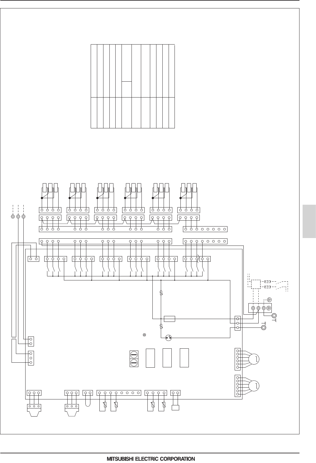
MEES19K085
BC controller
2 - 19
3. ELECTRICAL WIRING DIAGRAMS
BC controller
CMB-M106V-J1(-TR)
t°
t°
t°
t°
LD1:CPU in
operation
MM
UU
X02
X01
X30
X31
X03
X04
X06
X05
X32
X33
X34
X35
X21
X07
X09
X11
X08
X10
X12
ZNR02ZNR01
TH16
TH15
TH12
TH11
LEV3 LEV1
TO NEXT INDOOR UNIT
PULL BOX
FUSE(16A)
BREAKER(16A)
POWER SUPPLY
~220V-240V
50Hz/60Hz
DSA
CN29(Green)
CN28(Blue)
CN27(Red)
CN05
(Red)
CN07
(Yellow)
S(SHIELD)
M1
M2
TB02
Indoor/outdoor
Transmission line
3
1
SW2 SW1
110
F01
250VAC
6.3A F
2
2
3
1
3
1
TR
CN26
3
CNTR
(Red)
1
CN12
153654321
CONT. B
1
2
CN02
3
CNP1
(Black)
1
2
3
CNP3
1
2
3
4
5
6
7
8
4
3
2
1
12321
CN03
(Yellow)
CN10
CN11
PS1
PS3
654321
TB01
10
9
8
4
2
3
10
7
5
6
4
3
2
1
2
3
4
1
2
3
4
2
3
4
9
8
7
6
5
7
5
3
1
7
5
3
1
7
5
3
1
1
1
1
13
12
11
16
15
14
13
12
11
15
16
14
1
2
1
4
2
3
4
3
4
3
2
1
1
2
3
4
1
2
3
4
5
3
1
7
5
3
1
7
5
3
1
CN30(Black)
CN31(Yellow)
CN36(Green)
1
2
Z1
TYP1
5
6
5
8
6
7
8
7
1
2
CN13
(Red)
T5
SV5C
SV5A
SV5B
1
2
3
4
T6
SV1A
SV1B
T4
SV1C
1
SV6C
SV6A
SV6B
1
SV4C
2
SV4A
3
SV4B
4
1
2
3
4
2
3
4
T3
SV3C
SV3A
SV3B
1
2
3
4
T1
T2
SV2C
SV2A
SV2B
1
2
3
4
20V~22V 220V~240V
SW4
SW5
SW6
18
ON
OFF
18
ON
OFF
18
ON
OFF
L
N
Note 1. TB02 is transmission terminal block.
Never connect power line to it.
2. The initial set values of switch on CONT. B are as follows.
SW1:0
SW2:0
BC controller
(Symbol explanation)
Circuit
board
CONT. B
Pressure sensor
TR
TH11,12,15,16
LEV1,3
PS1,3
Symbol
Name
Transformer
Thermister sensor
Expansion valve
SV1~6A,B,C
Solenoid valve
TB01
Terminal block
(for power source)
TB02
Terminal block
(for Transmission)
T1~6
Terminal
F01
Fuse AC250V 6.3A F
Function setting connector
Z1

MEES19K085
BC controller
2 - 20
3. ELECTRICAL WIRING DIAGRAMS
BC controller
CMB-M108V-J1(-TR)
t°
t°
t°
t°
10 1
LD1:CPU in
operation
MM
UU
X30
X01
X02
X04
X03
X31
X32
X05
X06
X08
X07
X33
X10
X09
X34
X35
X21
X11
X12
X20
X18
X16
X14
X19
X17
X15
X13
X39
X38
X37
X36
LEV3 LEV1
ZNR01
ZNR02
DSA
TB01
TO NEXT INDOOR UNIT
PULL BOX
FUSE(16A)
BREAKER(16A)
POWER SUPPLY
~220V-240V
50Hz/60Hz
CN31(Yellow)
CN30(Black)
CN29(Green)
CN28(Blue)
CN27(Red)
CN05
(Red)
CN07
(Yellow)
CNP1
(Black)
M1
M2
TB02
S(SHIELD)
Indoor/outdoor
Transmission line
CN36(Green)
3
1
F01
250VAC
6.3A F
SW1SW2
1
3
2
3
1
2
CN12
333157135715717
5
CN34(Black)
CN33(Red)
CN32
CN35(Blue)
16
16 131415
9
101112 56784
4
5
687
9
12 11 10
15 14 13
43 2 1 43 21
1
3
5
4
3
2
1
3
2
4
1
3
2
4
1
7
1
3
5
7
1
3
5
7
1
3
5
7
1
3
5
7
1
3
5
7
1
1
1
4
3
2
4
3
2
4
3
2
1
4
3
2
11
12
13
8
9
10
5
6
7
14
15
16
8
9
10
11
12
13
5
6
7
14
15
16
1
2
1
2
33
4
3
2
1
7654321
CN39
3
1
CN52
CONT. B
6
54
3
2
1
6
54
3
2
1
1
2
3
1
2
3
CNP3
1
2
3
4
5
6
7
8
4
3
2
1
12321
CN03
(Yellow)
CN02
CN10
CN11
TH11
TH12
TH15
TH16
TR
PS1
PS3
CN50
1234567
135
13
CN38
CN26
3
1
CNTR
(Red)
REL. B
1
2
Z1
TYP1
1
2
CN13
(Red)
T1
T2
T3
T4
T5
T6
4
3
2
1
SV1C
SV1A
SV1B
1
2
3
4
SV2B
SV2A
SV2C
1
2
3
4
SV3B
SV3A
SV3C
1
2
3
4
SV4B
SV4A
SV4C
1
2
3
4
SV5B
SV5A
SV5C
1
2
3
4
SV6B
SV6A
SV6C
T7
1234
SV7B
SV7A
SV7C
T8
1234
SV8B
SV8A
SV8C
20V~22V 220V~240V
SW4
SW5
SW6
18
ON
OFF
18
ON
OFF
18
ON
OFF
L
N
Note 1. TB02 is transmission terminal block.
Never connect power line to it.
2. The initial set values of switch on
CONT. B are as follows.
SW1:0
SW2:0
Relay
REL. B
BC controller
Circuit
board
(Symbol explanation)
F01
Fuse AC250V 6.3A F
Terminal
T1~8
CONT. B
Terminal block
(for Transmission)
TB02
Terminal block
(for power source)
TB01
Solenoid valve
Expansion valve
Symbol
SV1~8A,B,C
TR
TH11,12,15,16
LEV1,3
PS1,3
Pressure sensor
Function setting connector
Z1
Thermister sensor
Transformer
Name

MEES19K085
BC controller
2 - 21
3. ELECTRICAL WIRING DIAGRAMS
BC controller
CMB-M1012, 1016V-J1(-TR)
t°
t°
t°
t°
LD1:CPU in
operation
MM
UU
X02
X41
X44
X47
X50
X53
X56
X01
X40
X43
X46
X49
X52
X55
X30
X42
X45
X48
X51
X54
X57
X31
X03
X04
X06
X05
X32
X33
X07
X08
X12
X11
X35
X34
X09
X10
X21
X20
X19
X39
X18
X17
X38
X37
X15
X16
X36
X13
X14
LEV3 LEV1
ZNR01
ZNR02
DSA
TB01
PULL BOX
FUSE(16A) BREAKER(16A)
POWER SUPPLY
~220V-240V
50Hz/60Hz
TO NEXT
INDOOR UNIT
M1
M2
TB02
S(SHIELD)
Indoor/outdoor
Transmission line
CN33(Red)
CN34(Black)
CN35(Blue)
CN36(Green)
CN31(Yellow)
CN30(Black)
CN29(Green)
CN28(Blue)
CN27(Red)
CN07
(Yellow)
CN05
(Red)
10 1
SW1SW2
CMB-M1016V-J1(-TR) ONLY
F01
250VAC
6.3A F
2
2
1
3
1
3
21
CNVCC1
(Blue)
3
CNVCC2
(Blue)
312
REL. B
CONT. B
CN39
13
1
35
CN12
CNOUT3
CNOUT1
13
1
2
3
8
7
6
5
4
3
2
1
4
CNOUT2
CNOUT4
6
54
3
2
1
6
54
3
2
1
1
2
3
CNP1
(Black)
1
2
3
CNP3
1
2
3
4
5
6
7
8
4
3
2
1
12321
CN03
(Yellow)
CN02
CN10
CN11
TH11
TH12
TH15
TH16
TR
CN38
3
1
CNTR
(Red)
4
1
2
3
4
5
6
7
8
3
2
1
PS1
PS3
4
5
6
8
9
7
10
12
11
13
15
14
16
3
4
2
1
1
3
2
8
9
10
11
12
13
3
2
4
1
5
6
7
14
15
16
4
3
2
1
4
3
2
1
4
3
2
1
4
3
2
1
4
3
2
1
1
2
3
4
3
4
2
1
CN44(Yellow)
CN45(Green)
7
7
5
3
1
7
5
3
1
CN41(Green)
CN43(Red)
CN42
5
7
7
5
3
1
7
5
3
1
5
3
1
3
CN40
(Yellow)
1
5
6
7
8
9
10
11
12
13
14
15
16
3
2
4
8
9
10
11
12
13
3
2
4
5
6
7
14
15
16
4
3
2
4
3
2
1
4
3
2
1
4
3
2
1
4
3
2
1
1
2
3
4
33
2
1
2
1
CN26
5
3
3
1
7
5
3
1
7
5
3
1
7
5
3
1
7
5
3
1
7
5
3
1
11
1
16
16
131415 9101112 56784
45687912 11 1015 14 13
1234123412341234
CN32
7531753175317531
1
1
2
Z1
TYP1
7
8
6
5
7
8
6
5
1
2
CN13
(Red)
T1
T2
T3
T4
T5
T6
SV1B
SV1A
SV1C
4
3
2
1
SV2C
SV2A
SV2B
4
3
2
1
SV3C
SV3A
SV3B
4
3
2
1
SV4C
SV4A
SV4B
4
3
2
1
SV5C
SV5A
SV5B
4
3
2
1
SV6C
SV6A
SV6B
4
3
2
1
T10 T9 T8 T7
SV10B
SV10A
SV10C
1
2
341
2
34
SV9B
SV9A
SV9C
1
2
34
SV8B
SV8A
SV8C
1
2
34
SV7B
SV7A
SV7C
T11
T12
T13
T14
T15
T16
SV11C
SV11A
SV11B
4
3
2
1
SV12C
SV12A
SV12B
4
3
2
1
SV13C
SV13A
SV13B
4
3
2
1
SV14C
SV14A
SV14B
4
3
2
1
SV15C
SV15A
SV15B
4
3
2
1
SV16C
SV16A
SV16B
4
3
2
1
20V~22V 220V~240V
L
N
SW4
SW5
SW6
18
ON
OFF
18
ON
OFF
18
ON
OFF
Relay
REL. B
BC controller
Circuit
board
(Symbol explanation)
CONT. B
Terminal block
(for Transmission)
TB02
Terminal block
(for power source)
TB01
Solenoid valve
Expansion valve
Thermister sensor
Transformer
Name
Symbol
SV1~16A,B,C
TR
TH11,12,15,16
LEV1,3
PS1,3
Pressure sensor
Terminal
T1~16
F01
Fuse AC250V 6.3A F
Z1
Function setting connector
Note 1. TB02 is transmission terminal block.
Never connect power line to it.
2. The initial set values of switch on CONT. B are as follows.
SW1:0
SW2:0

MEES19K085
BC controller
2 - 22
3. ELECTRICAL WIRING DIAGRAMS
BC controller
CMB-M108V-JA1(-TR)
LD1:CPU in
operation
SVM1
MM
X12
X11
X35
X34
X09
X10
X33
X07
X08
X06
X05
X32
X31
X03
X04
X02
X01
X30
X21
X60
X36
X13
X14
X37
X15
X16
X18
X17
X38
X20
X19
X39
U
ZNR02
U
ZNR01
CN03
(Yellow)
3
1
CN33(Red)
CN34(Black)
CN35(Blue)
CN39
POWER SUPPLY
~220V-240V
50Hz/60Hz
BREAKER(16A)
PULL BOX
FUSE(16A)
TO NEXT INDOOR UNIT
TB01
CN36(Green)
CN30(Black)
CN31(Yellow)
CN29(Green)
CN28(Blue)
CN27(Red)
CNTR
(Red)
DSA
M1
M2
TB02
S(SHIELD)
Indoor/outdoor
Transmission line
CN05
(Red)
CN07
(Yellow)
CNP1
(Black)
SW2 SW1
110
F01
250VAC
6.3A F
2
1
3
2
3
1
REL. B
1
3
CN26
CN38
31
CN12
531
7654321
CN50
PS3
PS1
TR
TH16
TH15
TH12
TH11
CN11
CN10
CN02
12321
1
2
3
4
8
7
6
5
4
3
2
1
CNP3
3
2
1
3
2
1
LEV1LEV3
123456123456
CONT. B
CN52
1234567
1
2
3
4
33
2
1
2
1
16
15
14
7
6
5
13
12
11
10
9
8
16
15
14
7
6
5
10
9
8
13
12
11
2
3
4
1
2
3
4
2
3
4
2
3
4
1
1
1
7
5
3
1
7
5
3
1
7
5
3
1
7
5
3
1
7
5
3
1
7
1
4
2
3
1
4
2
3
1
2
3
4
5
3
1
12341234
131415 101112 9 78 654
487 6512 11 10 915 14 1316
16
CN32
571751753175133 3
CN46(Yellow)
3
1
3
1
1234
4123
123
123
1
2
Z1
TYP1
X62
X61
CN47
1
3
5
6
56
65
456
456
SVM1b
78
87
M
LEV4
1
2
3
4
5
6
CN08
(Green)
2
1
CN13
(Red)
T1
T2
T3
T4
T5
T6
SV1B
SV1A
SV1C
1
2
3
4
SV2C
SV2A
SV2B
4
3
2
1
SV3C
SV3A
SV3B
4
3
2
1
SV4C
SV4A
SV4B
4
3
2
1
SV5C
SV5A
SV5B
4
3
2
1
SV6C
SV6A
SV6B
4
3
2
1
T7T8
SV7C
SV7A
SV7B
43 21
SV8C
SV8A
SV8B
43 21
20V~22V
220V~240V
L
N
SW4
SW5
SW6
18
ON
OFF
18
ON
OFF
18
ON
OFF
(Symbol explanation)
Circuit
board
BC controller
REL. B
Relay
Pressure sensor
TR
TH11,12,15,16
LEV1,3,4
PS1,3
SV1~8A,B,C
Name
Transformer
Thermister sensor
Expansion valve
Solenoid valve
TB01
Terminal block
(for power source)
TB02
Terminal block
(for Transmission)
CONT. B
SVM1,SVM1b
Solenoid valve
Terminal
T1~8
Fuse AC250V 6.3A F
F01
Function setting connector
Z1
Symbol
Note 1. TB02 is transmission terminal block.
Never connect power line to it.
2. The initial set values of switch on CONT. B are as follows.
SW1:0
SW2:0
t°
t°
t°
t°
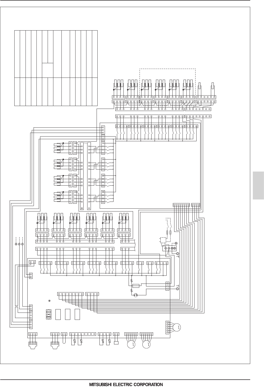
MEES19K085
BC controller
2 - 23
3. ELECTRICAL WIRING DIAGRAMS
BC controller
CMB-M1012, 1016V-JA1(-TR)
t°
t°
t°
t°
LD1:CPU in
operation
SVM1
M
M
X42
X40
X41
X43
X44
X45
X46
X47
X48
X49
X50
X51
X54
X52
X53
X57
X55
X56
UU
X30
X01
X02
X04
X03
X31
X32
X05
X06
X08
X07
X33
X10
X09
X34
X35
X11
X12
X21
X60
X16
X15
X37
X14
X13
X36
X39
X19
X20
X38
X17
X18
ZNR01
ZNR02
F01
250VAC
6.3A F
CNTR
(Red)
CN45(Green)
CN44(Yellow)
CN43(Red)
CN41(Green)
CN40
(Yellow)
CN34(Black)
CN33(Red)
CN35(Blue)
PULL BOX
FUSE(16A)
BREAKER(16A)
TO NEXT
INDOOR UNIT
POWER SUPPLY
~220V-240V
50Hz/60Hz
TB01
DSA
CN05
(Red)
CN07
(Yellow)
CNP1
(Black)
CNVCC1
(Blue)
CN03
(Yellow)
M1
M2
TB02
S(SHIELD)
Indoor/outdoor
Transmission line
10 1
SW1SW2
CMB-M1016V-JA1(-TR) ONLY
2
2
1
3
1
3
213
CNVCC2
(Blue)
312
REL. B
CONT. B
CN39
13
135
CN12
CNOUT3
CNOUT1
13
1
2
3
8
7
6
5
4
3
2
1
4
CNOUT2
CNOUT4
6
6
5
5
4
4
3
3
2
2
1
1
LEV1
LEV3
1
2
3
1
2
3
CNP3
1
2
3
4
5
6
7
8
4
3
2
1
12321
CN02
CN10
CN11
TH11
TH12
TH15
TH16
TR
CN38
3
1
4
1
2
3
4
5
6
7
8
3
2
1
PS1
PS3
4
5
6
8
9
7
10
12
11
13
15
14
16
3
4
2
1
1
3
2
8
9
10
11
12
13
3
2
4
1
5
6
7
14
15
16
4
3
2
1
4
3
2
1
4
3
2
1
4
3
2
1
4
3
2
1
1
3
4
3
4
2
1
7
7
5
3
1
7
5
3
1
CN42
5
7
7
5
3
1
7
5
3
1
5
3
1
3
1
5
6
7
8
9
10
11
12
13
14
15
16
3
2
4
8
9
10
11
12
13
3
2
4
5
6
7
14
15
16
4
3
2
4
3
2
1
4
3
2
1
4
3
2
1
4
3
2
1
1
2
3
4
33
2
1
2
1
CN31(Yellow)
CN30(Black)
CN29(Green)
CN28(Blue)
CN27(Red)
CN26
7
5
3
1
7
5
3
1
7
5
3
1
7
5
3
1
7
5
3
1
7
5
3
1
11
1
16
16
131415 9101112 56784
45687912 11 1015 14 13
1234123412341234
CN32
753133753175317531
3
1
3
1
CN36(Green)
CN46(Yellow)
3
22
3
1
1
2
1
2
Z1
TYP1
X62
X61
CN47
1
3
5
6
55
66
8
7
8
7
4
5
6
4
5
6
SVM1b
M
CN08
(Green)
6
5
4
3
2
1
LEV4
1
2
CN13
(Red)
(Symbol explanation)
Relay
REL. B
BC controller
Circuit
board
CONT. B
Terminal block
(for Transmission)
TB02
Terminal block
(for power source)
TB01
Solenoid valve
Expansion valve
Thermister sensor
Transformer
Name
SV1~16A,B,C
TR
TH11,12,15,16
LEV1,3,4
PS1,3
Pressure sensor
SVM1,SVM1b
T1~16
Terminal
Solenoid valve
F01
Fuse AC250V 6.3A F
Z1
Function setting connector
Symbol
2
2
SV4A
SV4B
2
3
3
4
T5
SV5C
SV5A
SV5B
1
1
T1
1
2
3
4
SV1B
1
SV1A
SV1C
1
2
3
4
T6
SV6C
SV6A
SV6B
4
1
T2
SV2C
SV2A
SV2B
2
3
4
T4
SV4C
3
4
T3
SV3C
SV3A
SV3B
SV11B
SV11A
T11
SV11C
4
3
2
1
T13
1
2
3
4
T15
SV13B
1
2
3
4
SV13A
SV13C
SV15B
SV15A
SV15C
T12
1
2
3
4
SV12B
SV12A
SV12C
T16
1
2
3
4
SV16B
SV16A
SV16C
1
2
3
4
T14
SV14B
SV14A
SV14C
T9
SV9B
SV9A
SV9C
SV10B
SV10A
SV10C
12341234
T7
SV7B
SV7A
SV7C
1234
T8
SV8B
SV8A
SV8C
T10
1234
20V~22V 220V~240V
L
N
SW4
SW5
SW6
18
ON
OFF
18
ON
OFF
18
ON
OFF
Note 1. TB02 is transmission terminal block.
Never connect power line to it.
2. The initial set values of switch on CONT. B are as follows.
SW1:0
SW2:0

MEES19K085
BC controller
2 - 24
3. ELECTRICAL WIRING DIAGRAMS
BC controller
CMB-P1016V-KA1(-TR)
t°
t°
t°
t°
1
10 1
SW1SW2
33
LD1:CPU in
operation
UU
DSA
CNVCC1
(Blue)
CN03
(Yellow)
CN02
22323111
3
2
1
CNP1
(Black)
1
2
3
TR
CN38
13
CNTR(Red)
3
1
CN26
X02
X01
X30
7
5
3
1
CN27(Red)
1
3
5
7
X31
X03
X04
CN28(Blue)
X06
X05
X32
1
3
5
7
CN29(Green)
X08
X07
X33
5
3
1
7
CN30(Black)
X10
1
3
5
7
X34
X09
CN31(Yellow)
X12
1
3
X11
X35
5
7
CN36(Green)
X21
1
3
CN46(Yellow)
X60
1
3
CN47
X62
X61
1
3
6
5
6
53
1
CN12
ZNR02
ZNR01
F01
250VAC
6.3A F
CNOUT3
2
3
4
1
8
7
6
5
4
3
2
1
CNOUT1
8
7
6
5
4
CN10
3
2
CNP3
3
2
1
1
3
2
1
PS3
PS1
TH11
TH12
CN11
4
3
2
1
TH15
TH16
Indoor/outdoor
Transmission line
TB02
S(SHIELD)
16
15
14
7
6
5
4
2
3
13
12
11
10
9
8
4
2
3
16
15
14
13
12
11
10
9
8
7
6
5
11
1
2
1
2
33
POWER SUPPLY
~220V-240V
50Hz/60Hz
BREAKER(16A)
FUSE(16A)
PULL BOX
TO NEXT
INDOOR UNIT
4
3
2
1
1
2
3
4
4
3
2
1
4
3
2
1
4
3
2
1
1
2
3
4
CNOUT4
CNOUT2
4
1
2
3
4
5
6
7
8
3
2
1
12
3
412
3
412
3
4
12
34
131415 101112 9 786
87 612 11 10 915 14 13
16
16
54
45
CN35(Blue)
X20
X19
X39
7531
CN34(Black)
X18
X17
X38
7531
CN33(Red)
X16
X15
X37
7531
CN39
CN32
1357
X36
X13
X14
CNVCC2
(Blue)
32131
CN40
(Yellow)
X41
X40
X42
1
3
5
7
CN41(Green)
X44
X43
X45
CN42
X47
X46
X48
CN43(Red)
X50
X49
X51
CN44(Yellow)
X53
X52
3
5
1
7
5
3
1
7
5
3
1
3
5
7
6
5
4
2
3
2
3
6
5
4
7
12
11
10
9
8
11
12
10
7
9
8
11
1
2
3
4
1
2
X54
CN45(Green)
X56
X55
X57
7
5
3
1
7
15
14
13
1
2
4
3
16
14
15
13
5
6
8
7
16
1
2
3
4
5
8
5
6
7
1
2
4
3
1
2
3
4
4
3
2
1
2
1
3
4
4
3
1
4
3
2
6
CONT. B
REL. B
M2
M1
TB01
M
M
CN05
(Red)
CN07
(Yellow)
6
6
5
5
4
4
3
3
2
2
1
1
LEV1
LEV3
1
2
Z1
TYP1
M
CN08
(Green)
6
5
4
3
2
1
LEV4
2
1
CN13
(Red)
5
4
3
2
1
6
SVM1
SVM1b
(Symbol explanation)
Fuse AC250V 6.3A F
F01
SVM1,1b
Solenoid valve
Solenoid valve
SV1~16A,B,C
TB02
Terminal block
(for Transmission)
Terminal block
(for power source)
TB01
CONT. B
REL. B
TR
TH11,12,15,16
LEV1,3,4
PS1,3
Name
Transformer
Thermister sensor
Expansion valve
Pressure sensor
Circuit
board
Relay
BC controller
T1~16
Terminal
Function setting connector
Z1
Symbol
Note 1. TB02 is transmission terminal block.
Never connect power line to it.
2. The initial set values of switch on CONT. B are as follows.
SW1:0
SW2:0
SV11B
SV11A
T11
SV11C
4
3
2
1
T13
1
2
3
4
T15
SV13B
1
2
3
4
SV13A
SV13C
SV15B
SV15A
SV15C
T12
1
2
3
4
SV12B
SV12A
SV12C
T16
1
2
3
4
SV16B
SV16A
SV16C
1
2
3
4
T14
SV14B
SV14A
SV14C
T9
SV9B
SV9A
SV9C
SV10B
SV10A
SV10C
12
3
412
3
4
T7
SV7B
SV7A
SV7C
12
3
4
T8
SV8B
SV8A
SV8C
T10
12
3
4
2
2
SV4A
SV4B
2
3
3
4
T5
SV5C
SV5A
SV5B
1
1
T1
1
2
3
4
SV1B
1
SV1A
SV1C
1
2
3
4
T6
SV6C
SV6A
SV6B
4
1
T2
SV2C
SV2A
SV2B
2
3
4
T4
SV4C
3
4
T3
SV3C
SV3A
SV3B
20V~22V 220V~240V
L
N
SW4
SW5
SW6
18
ON
OFF
18
ON
OFF
18
ON
OFF

MEES19K085
BC controller
2 - 25
3. ELECTRICAL WIRING DIAGRAMS
BC controller
CMB-M104V-KB1(-TR)
t°
t°
t°
10 1
SW1SW2
7
5
3
1
DSA
UU
LD1:CPU in
operation
TB01
CONT. B
1
2
3
4
1
2
3
4
4
3
2
1
1
2
3
4
TO NEXT
INDOOR UNIT
PULL BOX
FUSE(16A)
BREAKER(16A)
POWER SUPPLY
~220V-240V
50Hz/60Hz
11
5
6
7
8
9
10
11
12
13
14
15
16
3
2
4
8
9
10
11
12
13
3
2
4
5
6
7
14
15
16
S(SHIELD)
M2
M1
TB02
Indoor/outdoor
Transmission line
TH15
1
2
3
4
CN11
TH12
1
2
3
CN10
4
5
6
7
8
F01
250VAC
6.3A F
ZNR01
ZNR02
CN12
1
35
7
1
3
5
X33
X07
X08
CN29(Green)
7
5
3
1
X32
X05
X06
CN28(Blue)
X04
X03
X31
7
5
3
1
CN27(Red)
X30
X01
X02
CN26
CNTR
(Red)
TR
1132 2
CN02CN03
(Yellow)
TH16
M
LEV3
1
2
3
45
6
CN07
(Yellow)
1
2
Z1
TYP1
2
1
3
PS3
CNP3
3
2
1
2
1
CN13
(Red)
T1
T2
T3
T4
SV1A
SV1B
SV1C
1
2
3
4
SV2C
SV2A
SV2B
1
2
3
4
SV3C
SV3A
SV3B
1
2
3
4
SV4C
SV4A
SV4B
1
2
3
4
L
N
20V~22V 220V~240V
SW4
SW5
SW6
18
ON
OFF
18
ON
OFF
18
ON
OFF
3
1
Fuse AC250V 6.3A F
F01
Solenoid valve
SV1~4A,B,C
TB02
Terminal block
(for Transmission)
Terminal block
(for power source)
TB01
CONT. B
TR
TH12,15,16
LEV3
Name
Transformer
Thermister sensor
Expansion valve
Circuit
board
BC controller
Terminal
T1~4
Function setting connector
Z1
Pressure sensor
PS3
(Symbol explanation)
Symbol
Note 1. TB02 is transmission terminal block.
Never connect power line to it.
2. The initial set values of switch on CONT. B are as follows.
SW1:0
SW2:0

MEES19K085
BC controller
2 - 26
3. ELECTRICAL WIRING DIAGRAMS
BC controller
CMB-M108V-KB1(-TR)
10 1
LD1:CPU in
operation
M
LEV3
CN07
(Yellow)
SW1SW2
1
3
2
CONT. B
654321
1
2
3
CNP3
1
2
3
4
5
6
7
8
4
3
2
1
12321
CN03
(Yellow)
CN02
CN10
CN11
TH12
TH15
TH16
TR
PS3
CN50
6543217
1
2
Z1
TYP1
2
1
CN13
(Red)
UU
X30
X01
X02
X04
X03
X31
X32
X05
X06
X08
X07
X33
X10
X09
X34
X35
X21
X11
X12
X20
X18
X16
X14
X19
X17
X15
X13
X39
X38
X37
X36
ZNR01
ZNR02
DSA
TB01
TO NEXT INDOOR UNIT
PULL BOX
FUSE(16A)
BREAKER(16A)
POWER SUPPLY
~220V-240V
50Hz/60Hz
CN31(Yellow)
CN30(Black)
CN29(Green)
CN28(Blue)
CN27(Red)
M1
M2
TB02
S(SHIELD)
Indoor/outdoor
Transmission line
CN36(Green)
3
1
F01
250VAC
6.3A F
CN12
3331571357135713 75
CN34(Black)
CN33(Red)
CN32
CN35(Blue)
16
16 131415 9101112 56784
45687912 11 1015 14 13
43 2 1 43 21
1
3
5
4
3
2
1
3
2
4
1
3
2
4
1
7
1
3
5
7
1
3
5
7
1
3
5
7
1
3
5
7
1
3
5
7
1
1
1
4
3
2
4
3
2
4
3
2
1
4
3
2
11
12
13
8
9
10
5
6
7
14
15
16
8
9
10
11
12
13
5
6
7
14
15
16
1
2
1
2
33
4
3
2
1
7654321
CN39
3
1
CN52
135
13
CN38
CN26
3
1
CNTR
(Red)
REL. B
T1
T2
T3
T4
T5
T6
4
3
2
1
SV1C
SV1A
SV1B
1
2
3
4
SV2B
SV2A
SV2C
1
2
3
4
SV3B
SV3A
SV3C
1
2
3
4
SV4B
SV4A
SV4C
1
2
3
4
SV5B
SV5A
SV5C
1
2
3
4
SV6B
SV6A
SV6C
T7
123
4
SV7B
SV7A
SV7C
T8
123
4
SV8B
SV8A
SV8C
20V~22V 220V~240V
L
N
SW4
SW5
SW6
ON
18234567
ON
18234567
ON
18234567
Relay
REL. B
BC controller
Circuit
board
F01
Fuse AC250V 6.3A F
Terminal
T1~8
CONT. B
Terminal block
(for Transmission)
TB02
Terminal block
(for power source)
TB01
Solenoid valve
Expansion valve
Thermister sensor
Transformer
Name
SV1~8A,B,C
TR
TH12,15,16
LEV3
PS3
Pressure sensor
Z1
Function setting connector
(Symbol explanation)
Symbol
Note 1. TB02 is transmission terminal block.
Never connect power line to it.
2. The initial set values of switch on
CONT. B are as follows.
SW1:0
SW2:0
t°
t°
t°

MEES19K085
BC controller
2 - 27
4. SOUND LEVELS
BC controller
4. SOUND LEVELS
4-1. Sound levels in cooling mode
Depending on the operation conditions, the unit generates noise caused by valve actuation, refrigerant flow, and pressure changes when
operating normally. Please consider to avoid location where quietness is required.
The sound pressure level measured by the conventional method in JIS for reference purpose.
Measurement condition
Measurement location
1.5m
63 125 250 500 1k 2k 4k 8k dB(A)
36.0 42.0 47.0 43.0 41.5 42.5 38.0 29.0 48.0
Standard Cooling 60Hz
10
20
30
40
50
60
70
80
90
125 250 500 1k 2k 4k 8k
NC -40
NC -30
NC -20
NC -60
NC -50
NC -70
Octave band central frequency (Hz)
Octave band sound level (dB)
Sound level of CMB-P1016V-KA1(-TR)
63
Approximate minimum
audible limit on
continuous noise
63 125 250 500 1k 2k 4k 8k dB(A)
31.5 30.0 34.0 32.0 32.0 33.5 35.0 27.5 40.0
Standard Cooling 60Hz
10
20
30
40
50
60
70
80
90
125 250 500 1k 2k 4k 8k
NC -40
NC -30
NC -20
NC -60
NC -50
NC -70
Octave band central frequency (Hz)
Octave band sound level (dB)
Sound level of CMB-M104-1016V-J1(-TR)
63
Approximate minimum
audible limit on
continuous noise
63 125 250 500 1k 2k 4k 8k dB(A)
31.5 30.0 34.0 32.0 32.0 33.5 35.0 27.5 40.0
Standard Cooling 60Hz
10
20
30
40
50
60
70
80
90
125 250 500 1k 2k 4k 8k
NC -40
NC -30
NC -20
NC -60
NC -50
NC -70
Octave band central frequency (Hz)
Octave band sound level (dB)
Sound level of CMB-M104, 108V-KB1(-TR)
63
Approximate minimum
audible limit on
continuous noise
63 125 250 500 1k 2k 4k 8k dB(A)
39.0 43.0 46.0 43.0 43.0 45.5 41.0 34.5 50.0
Standard Cooling 60Hz
10
20
30
40
50
60
70
80
90
125 250 500 1k 2k 4k 8k
NC -40
NC -30
NC -20
NC -60
NC -50
NC -70
Octave band central frequency (Hz)
Octave band sound level (dB)
Sound level of CMB-M108-1016V-JA1(-TR)
63
Approximate minimum
audible limit on
continuous noise
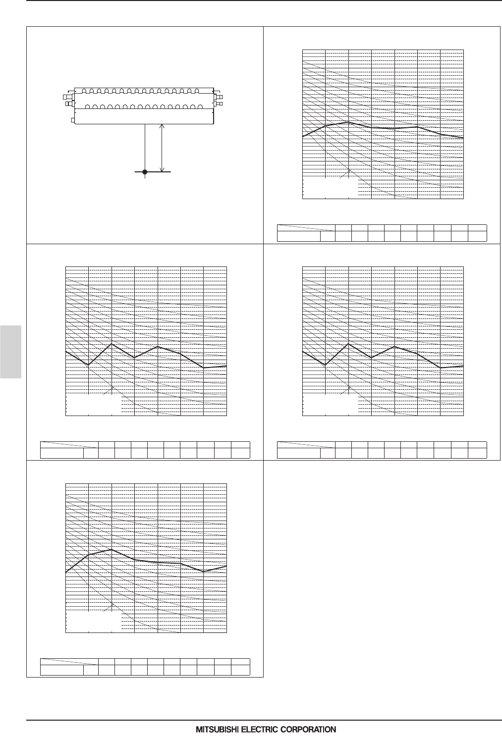
MEES19K085
BC controller
2 - 28
4. SOUND LEVELS
BC controller
4-2. Sound levels in heating mode
Depending on the operation conditions, the unit generates noise caused by valve actuation, refrigerant flow, and pressure changes when
operating normally. Please consider to avoid location where quietness is required.
The sound pressure level measured by the conventional method in JIS for reference purpose.
Measurement condition
Measurement location
1.5m
63 125 250 500 1k 2k 4k 8k dB(A)
43.0 49.0 51.0 48.0 47.5 48.5 44.5 42.5 54.0
60Hz
10
20
30
40
50
60
70
80
90
125 250 500 1k 2k 4k 8k
NC -40
NC -30
NC -20
NC -60
NC -50
NC -70
Octave band central frequency (Hz)
Octave band sound level (dB)
Sound level of CMB-P1016V-KA1(-TR)
63
Approximate minimum
audible limit on
continuous noise
Standard Heating
63 125 250 500 1k 2k 4k 8k dB(A)
44.5 37.0 48.5 41.0 47.0 43.0 35.5 36.5 50.0
Standard Heating 60Hz
10
20
30
40
50
60
70
80
90
125 250 500 1k 2k 4k 8k
NC -40
NC -30
NC -20
NC -60
NC -50
NC -70
Octave band central frequency (Hz)
Octave band sound level (dB)
Sound level of CMB-M104-1016V-J1(-TR)
63
Approximate minimum
audible limit on
continuous noise
63 125 250 500 1k 2k 4k 8k dB(A)
44.5 37.0 48.5 41.0 47.0 43.0 35.5 36.5 50.0
60Hz
10
20
30
40
50
60
70
80
90
125 250 500 1k 2k 4k 8k
NC -40
NC -30
NC -20
NC -60
NC -50
NC -70
Octave band central frequency (Hz)
Octave band sound level (dB)
Sound level of CMB-M104, 108V-KB1(-TR)
63
Approximate minimum
audible limit on
continuous noise
Standard Heating
63 125 250 500 1k 2k 4k 8k dB(A)
42.0 51.5 54.5 49.0 47.5 47.0 42.5 45.5 54.0
Standard Heating 60Hz
10
20
30
40
50
60
70
80
90
125 250 500 1k 2k 4k 8k
NC -40
NC -30
NC -20
NC -60
NC -50
NC -70
Octave band central frequency (Hz)
Octave band sound level (dB)
Sound level of CMB-M108-1016V-JA1(-TR)
63
Approximate minimum
audible limit on
continuous noise

MEES19K085
BC controller
2 - 29
4. SOUND LEVELS
BC controller
4-3. Sound levels in defrost mode
Depending on the operation conditions, the unit generates noise caused by valve actuation, refrigerant flow, and pressure changes when
operating normally. Please consider to avoid location where quietness is required.
The sound pressure level measured by the conventional method in JIS for reference purpose.
Measurement condition
Measurement location
1.5m
63 125 250 500 1k 2k 4k 8k dB(A)
40.0 52.0 54.5 46.5 45.0 47.5 49.5 46.0 55.0
Defrost 60Hz
10
20
30
40
50
60
70
80
90
125 250 500 1k 2k 4k 8k
NC -40
NC -30
NC -20
NC -60
NC -50
NC -70
Octave band central frequency (Hz)
Octave band sound level (dB)
Sound level of CMB-P1016V-KA1(-TR)
63
Approximate minimum
audible limit on
continuous noise
63 125 250 500 1k 2k 4k 8k dB(A)
47.0 47.0 51.0 49.0 48.0 46.5 41.5 30.5 53.0
Defrost 60Hz
10
20
30
40
50
60
70
80
90
125 250 500 1k 2k 4k 8k
NC -40
NC -30
NC -20
NC -60
NC -50
NC -70
Octave band central frequency (Hz)
Octave band sound level (dB)
Sound level of CMB-M104-1016V-J1(-TR)
63
Approximate minimum
audible limit on
continuous noise
63 125 250 500 1k 2k 4k 8k dB(A)
47.0 47.0 51.0 49.0 48.0 46.5 41.5 30.5 53.0
Defrost 60Hz
10
20
30
40
50
60
70
80
90
125 250 500 1k 2k 4k 8k
NC -40
NC -30
NC -20
NC -60
NC -50
NC -70
Octave band central frequency (Hz)
Octave band sound level (dB)
Sound level of CMB-M104, 108V-KB1(-TR)
63
Approximate minimum
audible limit on
continuous noise
63 125 250 500 1k 2k 4k 8k dB(A)
42.0 50.5 55.0 48.0 47.0 46.0 51.5 47.0 56.0
Defrost 60Hz
10
20
30
40
50
60
70
80
90
125 250 500 1k 2k 4k 8k
NC -40
NC -30
NC -20
NC -60
NC -50
NC -70
Octave band central frequency (Hz)
Octave band sound level (dB)
Sound level of CMB-M108-1016V-JA1(-TR)
63
Approximate minimum
audible limit on
continuous noise

MEES19K085
BC controller
2 - 30
5. ELECTRICAL CHARACTERISTICS
BC controller
5. ELECTRICAL CHARACTERISTICS
Symbols: MCA (Max. Circuit Amps), MFA (Max. Fuse Amps), RLA (Rated Load Amps)
BC controller
Power supply
RLA(A)
Hz Volts Range+-10% MCA(A) MFA(A)
CMB-M104V-J1 (-TR)
50/60
220
Max.: 264V
Min.: 198V
0.45
15
0.31
230 0.34
240 0.36
CMB-M106V-J1 (-TR)
220
0.65
0.45
230 0.48
240 0.52
CMB-M108V-J1 (-TR)
220
0.85
0.58
230 0.63
240 0.68
CMB-M1012V-J1 (-TR)
220
1.24
0.85
230 0.92
240 0.99
CMB-M1016V-J1 (-TR)
220
1.63
1.12
230 1.22
240 1.30
CMB-M108V-JA1 (-TR)
220
0.85
0.58
230 0.63
240 0.68
CMB-M1012V-JA1 (-TR)
220
1.24
0.85
230 0.92
240 0.99
CMB-M1016V-JA1 (-TR)
220
1.63
1.12
230 1.22
240 1.30
CMB-P1016V-KA1 (-TR)
220
1.63
1.12
230 1.22
240 1.30
CMB-M104V-KB1 (-TR)
220
0.40
0.28
230 0.30
240 0.32
CMB-M108V-KB1 (-TR)
220
0.79
0.55
230 0.59
240 0.63

MEES19K085
BC controller
2 - 31
6. OPTIONAL PARTS
BC controller
6. OPTIONAL PARTS
6-1. JOINT and REDUCER
CITY MULTI units can be easily connected by using Joint sets and Reducer sets provided by Mitsubishi Electric. Refer to section
"Piping Design" or the Installation Manual that comes with the Joint set or Reducer set for how to install the Joint set or Reducer set.
For Gas pipe:
*Pipe diameter is indicated by inside diameter.
CMY-Y102SS-G2
<Deformed pipe(Accessory)>
ø15.88
ø19.05
ø19.05
30
58
(2 Pcs.)
(Outside diameter)
(Outside diameter)
(Outside diameter)
ø19.05
ø19.05
ø12.7
ø15.88
ø15.88
ø12.7
28
30
37
36
18
ø
9.52
ø
9.52
ø
9.52
(Outside diameter)
ø
9.52
(2 Pcs.)
ø
6.35
20
For Liquid pipe:
mm
<Deformed pipe(Accessory)>
For Gas pipe: For Liquid pipe:
*Pipe diameter is indicated by inside diameter.
mm
CMY-Y102LS-G2
<Deformed pipe(Accessory)>
<Deformed pipe(Accessory)>
ø25.4
ø25.4
ø19.05
76
39
(2 Pcs.)
(2 Pcs.)
(2 Pcs.)
(Outside diameter)
(Outside diameter)
(Outside diameter)
(Outside diameter)
(Outside diameter)
(Outside diameter)
(Outside diameter)
54
41
45
42
54
30
37
ø22.2
ø25.4
ø25.4
ø28.58
ø19.05
ø25.4
ø15.88
ø25.4
ø19.05
ø19.05
ø12.7
ø19.05
ø15.88
ø22.2
ø9.52
ø12.7
ø12.7
40
20
(2 Pcs.)
(Outside diameter)
(Outside diameter)
ø12.7
ø9.52
23
20
ø9.52
ø6.35
CMY-R201S-G
mm
58
20
30
26
66
41
42
54
16
42
23
(Outside diameter)
(Outside diameter)
(Outside diameter)
(Outside diameter)
(Outside diameter)
For High pressure For Low pressure For Liquid line
(2 Pcs.)
(2 Pcs.)
(2 Pcs.)
(2 Pcs.)
(2 Pcs.)
ø19.05
ø15.88
ø19.05
ø19.05
ø25.4
ø19.05
ø25.4
ø19.05
ø25.4
ø22.2
ø25.4
ø25.4
ø28.6
ø12.7
ø12.7
ø9.52
ø12.7
ø9.52
ø15.88
<Accessory>
Note. Pipe diameter is indicated by inside diameter.
• Cover
·················
3 Pcs.
CMY-R202S-G
mm
<Accessory>
Note. Pipe diameter is indicated by inside diameter.
26
66
42
41
45
30
26
66
54
41
42
54
49
18
28
28
23
(2 Pcs.)
(2 Pcs.)
(2 Pcs.)
ø25.4
ø19.05
ø25.4
ø22.2
ø25.4
ø19.05
ø25.4
ø25.4
ø15.88
ø19.05
ø25.4
ø19.05
ø25.4
ø25.4
ø28.6
ø19.05
ø25.4
ø22.2
ø25.4
ø22.2
ø19.05
ø15.88
ø12.7
ø15.88
ø12.7
ø9.52
ø15.88
ø15.88
ø9.52
ø12.7
ø15.88
For High pressure For Low pressure For Liquid line
(Outside diameter)
(Outside diameter)
(Outside diameter)
(Outside diameter)
(Outside diameter)
(Outside diameter)
(Outside diameter)
(Outside diameter)
(Outside diameter)
(Outside diameter)
(Outside diameter)
• Cover
·················
3 Pcs.

MEES19K085
BC controller
2 - 32
6. OPTIONAL PARTS
BC controller
CMY-R203S-G
mm
For High pressure For Low pressure For Liquid line
(Outside diameter)
(Outside diameter)
(Outside diameter)
(Outside diameter)
(Outside diameter)
(Outside diameter)
(Outside diameter)
(Outside diameter)
(Outside diameter)
(Outside diameter)
26
66
54
41
42
30
30
90
46
41
28
49
18
42
54
23
(2 Pcs.)
(2 Pcs.)
ø25.4
ø19.05
ø25.4
ø25.4
ø28.6
ø19.05
ø25.4
ø22.2
ø25.4
ø15.88
ø19.05
ø31.75
ø25.4
ø31.75
ø31.75
ø28.6
ø19.05
ø25.4
ø12.7
ø15.88
ø15.88
ø12.7
ø15.88
ø22.2
ø25.4
ø25.4
ø28.6
ø9.52
ø12.7
<Accessory>
Note. Pipe diameter is indicated by inside diameter.
• Cover
·················
3 Pcs.
CMY-R204S-G
mm
For High pressure For Low pressure For Liquid line
(Outside diameter)
(Outside diameter)
(Outside diameter)
(Outside diameter)
(Outside diameter)
(Outside diameter)
(Outside diameter)
(Outside diameter)
(Outside diameter)
(Outside diameter)
(Outside diameter)
(Outside diameter)
(Outside diameter)
(Outside diameter)
(Outside diameter)
26
66
54
42
30
30
90
46
41
42
58
20
30
54
69
54
37
28
28
41
69
(2 Pcs.)
(2 Pcs.)
(2 Pcs.)
ø25.4
ø19.05
ø25.4
ø25.4
ø28.6
ø22.2
ø25.4
ø19.05
ø31.75
ø25.4
ø31.75
ø31.75
ø28.6
ø19.05
ø25.4
ø22.2
ø25.4
ø19.05
ø15.88
ø19.05
ø19.05
ø22.2
ø19.05
ø34.93
ø31.75
ø25.4
ø28.6
ø19.05
ø12.7
ø15.88
ø9.52
ø15.88
ø15.88
ø12.7
ø15.88
ø19.05
ø25.4
ø31.75
ø41.28
<Accessory>
Note. Pipe diameter is indicated by inside diameter.
• Cover
·················
3 Pcs.
CMY-R205S-G
mm
For High pressure For Low pressure For Liquid line
(Outside diameter)
(Outside diameter)
(Outside diameter)
(Outside diameter)
(Outside diameter)
(Outside diameter)
(Outside diameter)
(Outside diameter)
(Outside diameter)
(Outside diameter)
(Outside diameter)
(Outside diameter)
(Outside diameter)
(Outside diameter)
(Outside diameter)
(Outside diameter)
(Outside diameter)
(Outside diameter)
(Outside diameter)
26
66
30
90
46
41
42
30
69
54
37
69
30
90
69
46
55
45
41
42
54
54
41
45
23
(3 Pcs.)
(2 Pcs.)
(2 Pcs.)
(2 Pcs.)
(2 Pcs.)
(2 Pcs.)
ø25.4
ø19.05
ø25.4
ø31.75
ø25.4
ø31.75
ø31.75
ø28.6
ø19.05
ø25.4
ø22.2
ø25.4
ø19.05
ø34.93
ø31.75
ø25.4
ø28.6
ø19.05
ø15.88
ø12.7
ø31.75
ø41.28
ø31.75
ø25.4
ø31.75
ø34.93
ø31.75
ø31.75
ø28.6
ø31.75
ø25.4
ø25.4
ø15.88
ø19.05
ø25.4
ø22.2
ø25.4
ø25.4
ø28.6
ø25.4
ø31.75
ø19.05
ø25.4
ø25.4
ø15.88
ø9.52
ø12.7
<Accessory>
Note. Pipe diameter is indicated by inside diameter.
• Cover
·················
3 Pcs.

MEES19K085
BC controller
2 - 33
6. OPTIONAL PARTS
BC controller
CMY-R301S-G
mm
(Outside diameter)
(Outside diameter)
(Outside diameter)
Note. Pipe diameter is indicated by inside diameter.
80
80
80
ø28.6
ø22.2
ø22.2
ø19.05
ø15.88
ø19.05
CMY-R302S-G
mm
(Outside diameter)
(Outside diameter)
(Outside diameter)
(Outside diameter)
(Outside diameter)
Note. Pipe diameter is indicated by inside diameter.
92
50
80
80
80
(2 Pcs.)
(2 Pcs.)
(2 Pcs.)
ø34.93
ø41.28
ø28.6
ø34.93
ø28.6
ø22.2
ø22.2
ø19.05
ø15.88
ø19.05
CMY-R303S-G
mm
(Outside diameter)
(Outside diameter)
(Outside diameter)
(Outside diameter)
(Outside diameter)
Note. Pipe diameter is indicated by inside diameter.
(2 Pcs.)
80
80
80
80
80
ø28.6
ø22.2
ø22.2
ø19.05
ø12.7
ø19.05
ø9.52
ø12.7
ø15.88
ø19.05
CMY-R304S-G
mm
(Outside diameter)
(Outside diameter)
(Outside diameter)
(Outside diameter)
(Outside diameter)
Note. Pipe diameter is indicated by inside diameter.
92
50
80
80
80
(2 Pcs.)
(2 Pcs.)
(2 Pcs.)
ø34.93
ø41.28
ø28.6
ø34.93
ø28.6
ø22.2
ø22.2
ø19.05
ø15.88
ø19.05

MEES19K085
BC controller
2 - 34
6. OPTIONAL PARTS
BC controller
CMY-R305S-G
mm
(Outside diameter)
(Outside diameter)
(Outside diameter)
(Outside diameter)
(Outside diameter)
(Outside diameter)
Note. Pipe diameter is indicated by inside diameter.
(2 Pcs.)
80
80
80
80
80
50
ø28.6
ø22.2
ø22.2
ø19.05
ø12.7
ø19.05
ø9.52
ø12.7
ø15.88
ø19.05
ø28.6
ø34.93
CMY-R306S-G
mm
(Outside diameter)
(Outside diameter)
(Outside diameter)
(Outside diameter)
(Outside diameter)
Note. Pipe diameter is indicated by inside diameter.
80
80
80
80
80
ø15.88
ø19.05
ø28.6
ø22.2
ø22.2
ø19.05
ø12.7
ø16
ø9.52
ø15.88

MEES19K085
BC controller
2 - 35
6. OPTIONAL PARTS
BC controller
How to select Joint and Reducer
Items “B” is not necessary when J1-type BC controller is used.
AA
CCC
CC
BB
IUIU IU
BC controller
(Sub)
BC controller
(Sub)
BC controller
(Sub)
Outdoor/Heat source unit
IU: Indoor unit
BC controller
(Main)
A Branch joint
Between BC and
indoor units
CMY-Y102SS-G2 Total down-stream indoor unit capacity: -P200/-M200
CMY-Y102LS-G2 Total down-stream indoor unit capacity: P201-P250/-M201-M250
B Branch joint
Between Main BC
and Sub BC
CMY-R201S-G Total down-stream indoor unit capacity: -P350/-M350
CMY-R202S-G Total down-stream indoor unit capacity: P351-P600/-M351-M450
CMY-R203S-G Total down-stream indoor unit capacity: P601-P650
CMY-R204S-G Total down-stream indoor unit capacity: P651-P1000
CMY-R205S-G Total down-stream indoor unit capacity: P1001-
C Reducer
Between outdoor/
heat source
units and BC
CMY-R301S-G
For J1 type
(Outdoor/Heat source unit capacity: P200-P300/M200-M300)
CMY-R302S-G
For JA1 type
(Outdoor/Heat source unit capacity: P200-P900/M200-M300)
CMY-R304S-G For KA1 type (Outdoor/Heat source unit capacity: P200-P1000)
Between Main BC
and Sub BC
CMY-R303S-G For JA1 type (When using the Sub BC controller)
CMY-R305S-G For KA1 type (When using the Sub BC controller)
CMY-R306S-G For KB1 type

MEES19K085
BC controller
2 - 36
6. OPTIONAL PARTS
BC controller
6-2. JOINT KIT "CMY-R160-J1" FOR BC CONTROLLER
CMY-Y102SS-G2
Fig.1. CMY-R160-J1 applying scheme
1. Designing CMY-R160-J1 to a PURY/PQRY system
The maximum down-stream Indoor capacity for 1 port of BC
controller is P80/M80. When the down-stream Indoor capacity
is above P80/M80, Joint kit CMY-R160-J1 is needed to
combined 2 ports of BC controller to enlarge the capacity, like
Group 2 and 3 in Fig. 1.
Maximum 3 Indoor units are allowed to connect to 1 port of BC
controller or 2 combined ports of BC controller using CMY-
R160-J1.
When connecting Indoor units to 1 port of BC controller or 2
combined ports of BC controller using CMY-R160-J1 or CMY-
Y102SS-G2 is applicable, like Group 1 and 2 in Fig. 1
Caution: Mixed cooling and heating mode at the same time for
Indoor units connecting to 1 port or 2 combined ports is not
available.
2. Piping at the installation site
The connection of CMY-R160-J1 to BC controller and pipe leading to Indoor units is referable to Fig. 2. Non-oxidized brazing is
necessary. All piping must be careful to avoid foreign material getting inside.
After piping and air-tight testing, insulation work to the Joint and pipe should be done. Details is available at the Installation Manual.
Joint kit "CMY-R160-J1" for BC controller is used to combine 2 ports of the BC controller at a PURY/PQRY system so as to
enable down-stream Indoor capacity above P80/M80 as shown in Fig. 1.
ø15.88(5/8")
ø9.52(3/8")
ø19.05(3/4")
ø9.52(3/8")
ø15.88(5/8")
ø9.52(3/8")
226(8-29/32")
226(8-29/32")
60(2-3/8")
60(2-3/8")
Instruction
This sheet
Please prepare the following items in the field. Tape for insulation material sealing Extension pipe for refrigerant circuit
1pc 1pc 1pc
1pc for gas side 1pc for Iiquid side
8pcs 1pc 1pc2pcs
Cover 1 Cover 2 Cover 3 Band Reducer 2
Joint pipe(Small) Joint pipe(Large)
7 9
Reducer 1
8
6
5
4
3
2
2
1
1
OD19.05-ID22.2
OD19.05-ID15.88
The Joint kit include following items:
Cutting point
Have pipe expansion of indoor unit connecting port by
cutting the piping at the cutting point.
Remove burr after cutting the piping to prevent entering
the piping.
Check that there is no crack at the pipe expansion part.
Cutting point
2 Joint pipe (for liquid side) 3 Joint pipe (for gas side)
mm (in.)
Outdoor/Heat source unit
Joint kit
CMY-R160-J1
Joint
BC controller
IU IU IU
IU IU IU IU
Group1
Total Indoor Capacity
<=P80/M80
Group2
Total Indoor Capacity
P81 to P250
M80 to M140
Group3
Indoor Capacity
P100 to P250
M100 to M140
Piping to indoor unit
(Non-oxidized brazing)
Joint pipe (for liquid side)
2
Joint pipe(for gas side)
3
Fig.2. Connecting CMY-R160-J1
50
20
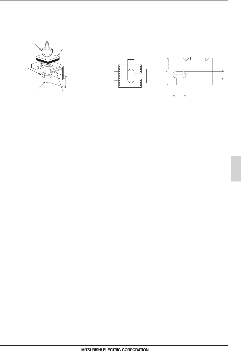
MEES19K085
BC controller
2 - 37
7. INSTALLATION
BC controller
7. INSTALLATION
7-1. Installing BC controllers
Installing hanging bolts
Install locally procured hanging bolts (threaded rod) following the procedure given in the figure.
The hanging bolt size is ø10 (M10 screw).
To hang the unit, use a lifting machine to lift and pass it through the hanging bolts.
ŹBe sure to install the BC controller horizontally, using a level. If the controller is installed at an angle, drain water may leak
out. If the controller is slanted, loosen the fixing nuts on the hanging brackets to adjust its position.
ŹProvide a downward pitch of 1.5º or below to the BC controller.
ŹDo not place the BC controller directly on the floor because the drain pan needs to be installed in a tilted position.
30mm
14mm
14mm
CMB-M104, 106, 108V-J1,
CMB-M104, 108V-KB1
Nut (not supplied)
Washer (without cushion) (supplied)
Minimum
30 mm
Washer (with cushion)(supplied)
* Attach the cushion facing down.
Double nut
(not supplied)
Hanging bolt ø10
(M10 screw)
(not supplied)
CMB-M1012, 1016V-J1
CMB-M108, 1012, 1016V-JA1
CMB-P1016V-KA1
30mm
(Top view)

MEES19K085
BC controller
2 - 38
8. SYSTEM DESIGN
BC controller
8. SYSTEM DESIGN
8-1. Compatibility
Outdoor/Heat source unit BC controller Compatibility
PURY-(E)M-YNW P-J type Not compatible
PURY-(E)M-YNW M-J1 type Compatible
PURY-(E)P-Y(S)NW
P-J type Compatible
PURY-(E)P-Y(S)LM S/W Ver. 7.08 or later
PQRY-P-Y(S)LM S/W Ver. 6.42 or later
PURY-RP-Y(S)JM S/W Ver. 5.58 or later
PURY-(E)P-Y(S)JM S/W Ver. 1.42 or later
PURY-(E)P-Y(S)NW
M-J1 type Compatible
PURY-(E)P-Y(S)LM S/W Ver. 7.08 or later
PQRY-P-Y(S)LM S/W Ver. 6.42 or later
PURY-RP-Y(S)JM S/W Ver. 5.58 or later
PURY-(E)P-Y(S)JM S/W Ver. 1.42 or later
Outdoor/Heat source unit
BC controller
Compatibility
Main Sub
PURY-(E)P-Y(S)NW P-JA type M-KB1 type Compatible
PURY-(E)P-Y(S)LM S/W Ver. 7.08 or later P-KA type M-KB1 type Compatible
PQRY-P-Y(S)LM S/W Ver. 6.42 or later M-JA1 type P-KB type Compatible
PURY-RP-Y(S)JM S/W Ver. 5.58 or later P-KA1 type M-KB1 type Compatible
PURY-(E)P-Y(S)JM S/W Ver. 1.42 or later P-JA type P-KB type Compatible
P-KA type P-KB type Compatible
P-KA1 type P-KB type Compatible
M-JA1 type M-KB1 type Compatible
Outdoor/Heat source unit
BC controller
Compatibility
Main Sub
PURY-(E)M-YNW P-JA type M-KB1 type Not compatible
P-KA type M-KB1 type Not compatible
M-JA1 type P-KB type Not compatible
P-KA1 type M-KB1 type Not compatible
P-JA type P-KB type Not compatible
P-KA type P-KB type Not compatible
P-KA1 type P-KB type Not compatible
M-JA1 type M-KB1 type Compatible
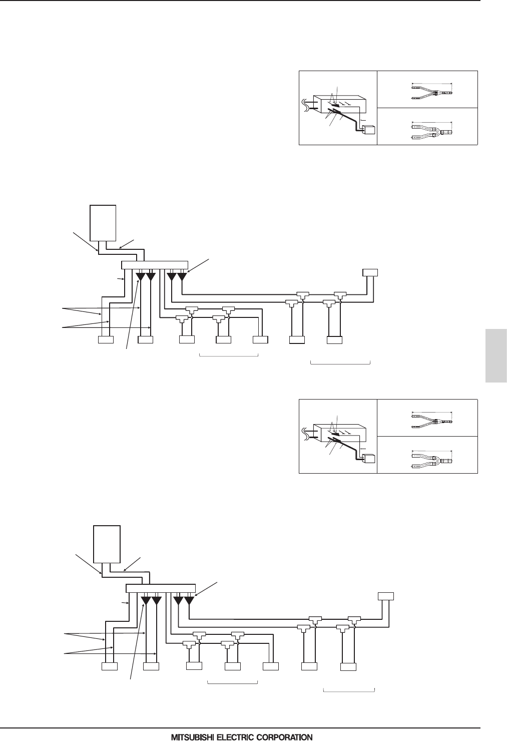
MEES19K085
BC controller
2 - 39
8. SYSTEM DESIGN
BC controller
8-2. System examples
Refer to “6-1. JOINT and REDUCER” and “Piping Design of Outdoor/Heat source Units” for joint/reducer selection rules, pipe
length restrictions, and pipe diameter.
8-2-1. When M-J1-type BC controller is used
8-2-2. When P-J-type BC controller is used
Note1. No Header usable on PURY system.
Note2. Indoor unit sized P100-P250/M100-M140 should be connected to BC controller via Y shape joint
CMY-R160-J1 ; If the system consists only of PEFY-P50, 63, 71, 80, 100VMHS2-E models of indoor units,
connect to the BC controller via Y-shape joint CMY-R160-J1.
Note3. Indoor unit sized P100-P250/M100-M140 does NOT share BC controller ports with other Indoor units ;
Note4. As bents cause pressure loss on transportation of refrigerant, fewer bents design is better ;
Piping length needs to consider the actual length and equivalent length which bents are counted.
Equivalent piping length (m)=Actual piping length+"M" x Number of bent.
Note5. Set DIP-SW 4-6 to ON of BC controller, in case of connected Indoor unit sized P100-P250/M100-M140 with
2 ports. If the system consists only of PEFY-P50, 63, 71, 80, 100VMHS2-E models of indoor units, set the
dipswitches SW4-1 and SW4-6 on the BC controller to ON.
Note6. It is also possible to connect Indoor unit sized P100-P140/M100-M140 with 1 port (set DIP-SW 4-1 and 4-6
to OFF). PEFY-P50, 63, 71, 80, 100VMHS2-E models of indoor units can be connected to the system using
a single port. However, the cooling capacity decreases a little.
Note7. Do not connect multiple indoor units to the same port when operating each of them in different mode (cooling, heating, stop, and thermo-off). The indoor units connected to the same port
must be set to operate in the same mode. Set them in the same group to make them run/stop in the same mode all together. For other options, enable the thermo setting on the remote
controller, or set the common thermostat (optional) to run/stop the units in the same mode based on a representative temperature.
Note8. Indoor capactiy is described as its model size. For example, PEFY-P63VML-E, its capacity is P63.
Note9. Total down-stream Indoor capacity is the summary of the model size of Indoors down-stream. For example, PEFY-P63VML-E + PEFY-P32VML-E: Total Indoor capacity = P63 + P32 = P95.
Note10. To enable the continuous heating mode, set SW4 (848) to ON.
Note11. To connect the BC controller to the main pipe, use the reducer.
S
T
M
N
CMY-R160-J1
(
Gas
side)
IU
CMY-R160-J1
(
Liquid
side)
BC controller
IU: Indoor unit
(T)ø19.05ID
(N)ø9.52ID
(M)ø3/8"(Brazing)
(M)ø3/8"(Brazing)
(S)ø5/8"(Brazing)
(S)ø5/8"(Brazing)
226
226
Joint CMY-R160-J1 Gas side
Joint CMY-R160-J1 Liquid side
Refer to the
installation manual
for the connection
CMY-R160-J1 (joint)
Possible to remove P140/M140 and under P140/M140, but the
capacity should be multiplied by a correction factor 0.97
CMY-R160-J1 (joint)
Possible to remove the total capacity P140 and under P140,
but the capacity should be multiplied by a correction factor 0.97
Pipe (Low pressure)
Pipe (High pressure)
Pipe (Liquid)
Pipe (Gas)
(P10-P80/M20-M80)
(P15-P80)
(P100-P250/M100-M140)
Max. 3 sets for 1 port.
Total capacity < = P80/M80
Max. 3 sets for 2 port.
Total capacity > P80/M80
IU (each) max < = P80/M80
BC controller (J1 type)
IU
IU
IU
IU
IU
IU
IU
IU
Outdoor/Heat source unit
PURY-(E)P-Y(S)NW
PURY-(E)M-YNW
PURY-(E)P-Y(S)LM S/W Ver. 7.08 or later
PQRY-P-Y(S)LM S/W Ver. 6.42 or later
PURY-RP-Y(S)JM S/W Ver. 5.58 or later
IU: Indoor unit
Note1. No Header usable on PURY system.
Note2. Indoor unit sized P100-P250 should be connected to BC controller via Y shape joint CMY-R160-J1 ;
Note3. Indoor unit sized P100-P250 does NOT share BC controller ports with other Indoor units ;
Note4. As bents cause pressure loss on transportation of refrigerant, fewer bents design is better ;
Piping length needs to consider the actual length and equivalent length which bents are counted.
Equivalent piping length (m)=Actual piping length+"M" x Number of bent.
Note5. Set DIP-SW 4-6 to ON of BC controller, in case of connected Indoor unit sized P100-P250 with 2 ports.
Note6. It is also possible to connect Indoor unit sized P100-P140 with 1 port (set DIP-SW 4-6 to OFF).
However, the cooling capacity decreases a little.
Note7. Do not connect multiple indoor units to the same port when operating each of them in different mode
(cooling, heating, stop, and thermo-off). The indoor units connected to the same port must be set to
operate in the same mode. Set them in the same group to make them run/stop in the same mode all
together. For other options, enable the thermo setting on the remote controller, or set the common
thermostat (optional) to run/stop the units in the same mode based on a representative temperature.
Note8. Indoor capactiy is described as its model size. For example, PEFY-P63VML-E, its capacity is P63.
Note9. Total down-stream Indoor capacity is the summary of the model size of Indoors down-stream.
For example, PEFY-P63VML-E + PEFY-P32VML-E : Total Indoor capacity = P63 + P32 = P95.
Note10. To enable the continuous heating mode, set SW4 (848) to ON.
S
T
M
N
CMY-R160-J1
(
Gas
side)
IU
CMY-R160-J1
(
Liquid
side)
BC controller
(T)ø19.05ID
(N)ø9.52ID
(M)ø3/8"(Brazing)
(M)ø3/8"(Brazing)
(S)ø5/8"(Brazing)
(S)ø5/8"(Brazing)
226
226
Joint CMY-R160-J1 Gas side
Joint CMY-R160-J1 Liquid side
Refer to the
installation manual
for the connection
CMY-R160-J1 (joint)
Possible to remove P140 and under P140, but the
capacity should be multiplied by a correction factor 0.97
CMY-R160-J1 (joint)
Possible to remove the total capacity P140 and under P140,
but the capacity should be multiplied by a correction factor 0.97
Pipe (Low pressure)
Pipe (High pressure)
Pipe (Liquid)
Pipe (Gas)
(P10-P80)
(P15-P80)
(P100-P250)
Max. 3 sets for 1 port.
Total capacity < = P80
Max. 3 sets for 2 port.
Total capacity > P80
IU (each) max < = P80
BC controller (J type)
IU
IU
IU
IU
IU
IU
IU
IU
Outdoor/Heat source unit
PURY-(E)P-Y(S)NW
PURY-(E)P-Y(S)LM S/W Ver. 7.08 or later
PQRY-P-Y(S)LM S/W Ver. 6.42 or later
PURY-RP-Y(S)JM S/W Ver. 5.58 or later

MEES19K085
BC controller
2 - 40
8. SYSTEM DESIGN
BC controller
8-2-3. When M-JA1/P-KA1- and M-KB1/P-KB-type BC controllers are used together
8-2-4. When P-JA/KA- and M-KB1/P-KB-type BC controllers are used together
IU: Indoor unit
Note1. No Header usable on PURY system.
Note2. Indoor unit sized P100-P250/M100-M140 should be connected to BC controller via Y shape joint
CMY-R160-J1 ; If the system consists only of PEFY-P50, 63, 71, 80, 100VMHS2-E models of indoor units,
connect to the BC controller via Y-shape joint CMY-R160-J1.
Note3. Indoor unit sized P100-P250/M100-M140 does NOT share BC controller ports with other Indoor units ;
Note4. As bents cause pressure loss on transportation of refrigerant, fewer bents design is better ;
Piping length needs to consider the actual length and equivalent length which bents are counted.
Equivalent piping length (m)=Actual piping length+"M" x Number of bent.
Note5. Set DIP-SW 4-6 to ON of BC controller, in case of connected Indoor unit sized P100-P250/M100-M140 with
2 ports.If the system consists only of PEFY-P50, 63, 71, 80, 100VMHS2-E models of indoor units, set the
dipswitches SW4-1 and SW4-6 on the BC controller to ON.
Note6. It is also possible to connect Indoor unit sized P100-P140/M100-M140 with 1 port (set DIP-SW 4-1 and 4-6
to OFF). PEFY-P50, 63, 71, 80, 100VMHS2-E models of indoor units can be connected to the system using
a single port. However, the cooling capacity decreases a little.
Note7. Do not connect multiple indoor units to the same port when operating each of them in different mode (cooling, heating, stop, and thermo-off). The indoor units connected to the same
port must be set to operate in the same mode. Set them in the same group to make them run/stop in the same mode all together. For other options, enable the thermo setting on the
remote controller, or set the common thermostat (optional) to run/stop the units in the same mode based on a representative temperature.
Note8. The maximum total capacity of indoor units that can be connected to each sub BC controller CMB-P
•
V-KB is 350.
Note9. Indoor capactiy is described as its model size. For example, PEFY-P63VML-E, its capacity is P63.
Note10. Total down-stream Indoor capacity is the summary of the model size of Indoors down-stream. For example,
PEFY-P63VML-E + PEFY-P32VML-E : Total Indoor capacity = P63 + P32 = P95.
Note11. To enable the continuous heating mode, set SW4 (848) to ON.
Note12. To connect the BC controller to the main pipe, use the reducer.
Note13. To connect the sub BC controller to the main BC controller, use the reducer.
S
T
M
N
CMY-R160-J1
(
Gas side)
IU
CMY-R160-J1
(
Liquid side)
BC controller
Pipe (Low pressure)
Pipe (High pressure)
(T)ø19.05ID
(N)ø9.52ID
(M)ø3/8"(Brazing)
(M)ø3/8"(Brazing)
(S)ø5/8"(Brazing)
(S)ø5/8"(Brazing)
226
226
Joint CMY-R160-J1 Gas side
Joint CMY-R160-J1 Liquid side
CMY-R160-J1 (joint)
Possible to remove P140/M140 and under P140/M140, but the
capacity should be multiplied by a correction factor 0.97
CMY-R160-J1 (joint)
Possible to remove the total capacity P140 and under P140,
but the capacity should be multiplied by a correction factor 0.97
(P10-P80/M20-M80)
(P15-P80)
(P10-P80/M20-M80) (P10-P80/M20-M80) (P10-P80/M20-M80)
(P100-P250
/M100-M140
)
Max. 3 sets for 1 port.
Total capacity < = P80/M80
Max. 3 sets for 2 port.
Total capacity > P80/M80
IU (each) max < = P80/M80
IU IU
IUIU IU
IU
IU
IU
IU
BC controller (KB(1) type)
BC controller (KB(1) type)
BC controller (KB(1) type)
IUIU
BC controller (KB(1) type)
IU
Pipe (LP Gas)
Pipe (HP Gas)
Pipe (Liquid)
Pipe (Gas)
Pipe
(Liquid)
Outdoor/Heat source unit
PURY-(E)P-Y(S)NW
PURY-(E)M-YNW
PURY-(E)P-Y(S)LM S/W Ver. 7.08 or later
PQRY-P-Y(S)LM S/W Ver. 6.42 or later
PURY-RP-Y(S)JM S/W Ver. 5.58 or later
BC controller
(JA1/KA1 type)
IU: Indoor unit
Note1. No Header usable on PURY system.
Note2. Indoor unit sized P100-P250 should be connected to BC controller via Y shape joint CMY-R160-J1 ;
If the system consists only of PEFY-P50, 63, 71, 80, 100VMHS2-E models of indoor units, connect to the
BC controller via Y-shape joint CMY-R160-J1.
Note3. Indoor unit sized P100-P250 does NOT share BC controller ports with other Indoor units ;
Note4. As bents cause pressure loss on transportation of refrigerant, fewer bents design is better ;
Piping length needs to consider the actual length and equivalent length which bents are counted.
Equivalent piping length (m)=Actual piping length+"M" x Number of bent.
Note5. Set DIP-SW 4-6 to ON of BC controller, in case of connected Indoor unit sized P100-P250 with 2 ports.
If the system consists only of PEFY-P50, 63, 71, 80, 100VMHS2-E models of indoor units, set the dipswitches
SW4-1 and SW4-6 on the BC controller to ON.
Note6. It is also possible to connect Indoor unit sized P100-P140 with 1 port (set DIP-SW 4-1 and 4-6 to OFF).
PEFY-P50, 63, 71, 80, 100VMHS2-E models of indoor units can be connected to the system using a single port.
However, the cooling capacity decreases a little.
Note7. Do not connect multiple indoor units to the same port when operating each of them in different mode (cooling, heating, stop, and thermo-off). The indoor units connected to the same
port must be set to operate in the same mode. Set them in the same group to make them run/stop in the same mode all together. For other options, enable the thermo setting on the
remote controller, or set the common thermostat (optional) to run/stop the units in the same mode based on a representative temperature.
Note8. For sub BC controller CMB-P•V-GB1 the connectable indoor unit capacities may sum to equal that of a P350 unit or less.
However, if two sub controllers are used the TOTAL sum of connectable units connected to BOTH sub controllers must also not exceed that of a P350 unit.
For sub BC controller CMB-P1016V-HB1 the connectable indoor unit capacities may sum to equal that or a P350 unit or less. However, if two sub controllers are used
the TOTAL sum of connectable units connected to BOTH sub controllers must also not exceed that of a P450 unit.
Note9. Indoor capactiy is described as its model size. For example, PEFY-P63VML-E, its capacity is P63.
Note10. Total down-stream Indoor capacity is the summary of the model size of Indoors down-stream. For example,
PEFY-P63VML-E + PEFY-P32VML-E : Total Indoor capacity = P63 + P32 = P95.
Note11. To enable the continuous heating mode, set SW4 (848) to ON.
Note12. To connect the BC controller to the main pipe, use the reducer.
Note13. To connect the sub BC controller to the main BC controller, use the reducer.
S
T
M
N
CMY-R160-J1
(
Gas side)
IU
CMY-R160-J1
(
Liquid side)
BC controller
CMY-R160-J1 (joint)
Possible to remove P140 and under P140, but the
capacity should be multiplied by a correction factor 0.97
CMY-R160-J1 (joint)
Possible to remove the total capacity P140 and under P140,
but the capacity should be multiplied by a correction factor 0.97
(P15-P80)
(P15-P80) (P15-P80)
(P100-P250)
Max. 3 sets for 1 port.
Total capacity < = P80
Max. 3 sets for 2 port.
Total capacity > P80
IU (each) max < = P80
IU IU
IUIU IU
IU
IU
IU
BC controller (KB(1) type)
BC controller (KB(1) type)
IUIU
BC controller (JA/KA type)
Pipe (LP Gas)
Pipe (HP Gas)
Pipe (Liquid)
Pipe (Gas)
Pipe
(Liquid)
Pipe (Low pressure)
Pipe (High pressure)
(T)ø19.05ID
(N)ø9.52ID
(M)ø3/8"(Brazing)
(M)ø3/8"(Brazing)
(S)ø5/8"(Brazing)
(S)ø5/8"(Brazing)
226
226
Joint CMY-R160-J1 Gas side
Joint CMY-R160-J1 Liquid side
Outdoor/Heat source unit
PURY-(E)P-Y(S)NW
PURY-(E)P-Y(S)LM S/W Ver. 7.08 or later
PQRY-P-Y(S)LM S/W Ver. 6.42 or later
PURY-RP-Y(S)JM S/W Ver. 5.58 or later
