
User's Guide
Qognify Cayuga R17
©2021 Qognify GmbH

Contents
Contents
Contents 2
Legal notice 5
Introduction 7
Login 9
2.1 Logging in for the first time 11
2.2 Advanced login options 12
2.3 Logging in Viewer Mode 13
The user interface 15
3.1 The function bar 16
The menu items 17
File menu 17
View 34
Tools 44
Info 54
Help 60
Changing the user 61
3.2 The mode bar 62
3.3 The control bar 62
3.4 Search 64
Surveillance mode 65
4.1 Work area 66
Creating layers 67
Setting the viewing mode on multiple windows 67
4.2 Sequential alarm window 68
4.3 Click-2-Track 68
4.4 Custom layers 70
4.5 Camera image controller 72
Camera image control icons 72
Mini archive player 73
Manual alarm recording 74
Swiveling the camera in the image 75
Camera image statistics 76
4.6 Maps 76
Displaying a camera preview 77
Using the lasso function 77
4.7 Web pages 78
4.8 Overview 79
2 / 120

4.9 Control 80
PTZ control 80
Buttons 83
Patrol 84
Audio 85
Dispatcher mode 86
4.10 Alarm list and system messages 87
Alarm messages 88
System messages 90
4.11 Searching in surveillance mode 91
Archive mode 93
5.1 Archive player 94
Using the jog dial 95
Timeline / time stream 95
Editing an area 95
Click-2-Track 96
5.2 Exporting recordings 97
Exporting the Click-2-Track history with the Export Designer 97
Evaluating exported video data 98
5.3 Write protection 99
Set write protection 99
Remove write protection 99
5.4 Searching for alarms 100
Creating an alarm query 101
Alarm search results 101
5.5 Working with bookmarks 102
Adding a bookmark 103
Bookmark overview 104
5.6 Edge storage import 105
Manual edge storage import 105
5.7 iSearch 105
Configuring iSearch 106
iSearch in expert mode 107
Deleting a search area 108
Report mode 109
6.1 Filtering the query 109
6.2 Exporting the analysis as spreadsheet file 110
6.3 Saving a query as report template 111
Shortcut keys 113
Anywhere Viewer 115
8.1 Switching the interface language 116
8.2 Import and play recording 116
8.3 Export a recording 118
Contents
3 / 120


Legal notice
This document is an integral part of the software shipped by Qognify
(referred to hereinafter as the vendor) and describes how to use and con-
figure the software and the associated components.
The English version of the document is the original version. All translations
are based on the English original.
Copyright
This document is protected by copyright. It is not permissible to pass on the
information it contains to third parties without the vendor's expression per-
mission. Any infringements will result in claims for damages.
Patent and copy protection
In the event of protection being provided by a patent, utility model or
registered design, all rights are reserved. Brand names and product names
are trade names or registered trademarks of their companies or organ-
izations.
Address
Qognify GmbH
Werner-von-Siemens-Str. 2 - 6
D-76646 Bruchsal
Tel: +49 (0)7251/9290-0
Fax: +49 (0)7251/9290-815
Email: [email protected]
Internet: https://www.qognify.com
Disclaimer
Subject to alterations without further notice. Suggestions regarding the
improvement of this documentation are welcome. For suggestions, refer to
Support.
Version
This manual corresponds to Qognify Cayuga R17 (Version 6.17.1).
Legal notice
5 / 120

7 / 120
Introduction
Qognify is a leading vendor of video management software and has been
developing and distributing software solutions for security applications since
the year 2000. Qognify also offers industry-specific solutions for trans-
portation and logistics, retail and trade, financial services and critical infra-
structure and cities.
The Multi Solution Platform system concept provides the basis for this. In
addition to the core products Qognify S50, S100 and Infinity, it includes a
wide range of expansion options and interfaces to numerous third-party sys-
tems in the fields of access control and building management, for example. As
a modular software construction kit, the Multi Solution Platform allows cus-
tom, industry-specific video solutions to be implemented that are infinitely
scalable over time.
In this guide you will find information on the installation and configuration of
the Cayuga software and an overview of the frequently used functions.
Product lines
n
Qognify Cayuga S50/S50X is a powerful entry-level solution for small-
scale projects involving up to 50 cameras.
n
Qognify Cayuga S100: This is the Qognify solution for medium-sized
installations. It allows intelligent video analysis to be used and third-party
systems to be integrated.
1

Introduction
n
Qognify Cayuga Infinity / Infinity X provides the most extensive functional
scope. There is no limit on the size of the projects that can be imple-
mented. Up to 5000 cameras are supported.
Fig. 1-1: Product lines
8 / 120

9 / 120
Login
Once the system is installed, you have to log in on the client to use the
installed services.
To automate the startup of the client, command line parameters can be
defined, e.g. to start the client with a different language or with predefined
passwords.
KEEP THE ADMINISTRATOR'S PASSWORD IN A SECURE PLACE!
If you forget the administrator's password and no additional users have
been added to the administrator group, it is no longer possible to access
the system configuration settings. The administrator password cannot be
restored.
2

Login
1. Start the Qognify Cayuga client in the Qognify folder in the Start menu
or on the desktop.
Fig. 2-1: Login
2. Select the Authentication method. The following authentication methods
are available:
—
Basic authentication with user name and password as defined in the con-
figuration within Cayuga.
—
Windows authentication with the current user credentials of the Win-
dows operating system, i.e. the same login as required for logging into
the system. The user will have the rights of the groups he is in.
—
Windows authentication with the user’s Active Directory (AD) cre-
dentials. The user will have the rights of the groups he is in.
This feature can only be used if the use of Active Directory (AD) is
part of the Cayuga license.
3. If Basic Authentication is selected, enter the user name and the pass-
word.
Make sure the user name and password are entered correctly, as the
system distinguishes between upper and lower case (case-sensitive).
4. Apply by clicking the arrow. The client is started in surveillance mode
(see Surveillance mode, p. 65).
In Viewer mode, Cayuga is used for the display of exported data in
Archive mode (see Anywhere Viewer, p. 115).
10 / 120

2.1 Logging in for the first time
Changing the password
When logging in for the first time, you are required to modify the default user
password.
Fig. 2-2: Change password
1. Enter the User name ("administrator") and default Password ("pass").
2. Enter your new password.
3. Disable Enforce secure password if you do not require increased pass-
word security.
4. If necessary, enter a second password.
5. Click OK.
Changing the database backup password
Database backups are encrypted and require a password. When logging in for
the first time, you are required to modify the default database backup pass-
word.
Fig. 2-3: Change the database backup password
Login
2.1 Logging in for the first time
11 / 120

Login
2.2 Advanced login options
1. Enter der the database backup password.
2. Repeat the new database backup password.
3. Click OK.
2.2 Advanced login options
In the advanced options of the login screen, additional user management func-
tions or log in as a user with two passwords is configured.
1. Click Advanced options in the login window.
Fig. 2-4: Advanced login options
The following options are available:
n
Last used: list of previously connected servers
n
Server: name and port of a different server
n
Second password if required for login
n
Comment: additional information for the selected login.
12 / 120

n
Remember user name and Remember password: avoids having to enter
the user data for log in. The system enters the specified user name and
password in the login window.
Due to legal regulations, in France the user name and password may
not be saved for installations.
n
Log in automatically: displays the user interface when the program starts
up (without log in).
n
Use NAT: enables the client to access a different server over the internet.
Deselect this option if no internet connection is required. This option
requires NAT-settings in configuration mode.
n
To login to all installations with the same user name and password, select
Use local credentials for all installations. Optionally this option can be
activated in the installation manager (see Disconnect and reconnect a Qog-
nify installation, p. 33).
In this case make sure that the remote user are the same as the local cre-
dentials.
KEEP THE ADMINISTRATOR'S PASSWORD IN A SECURE PLACE!
If you forget the administrator's password and no additional users have
been added to the administrator group, it is no longer possible to access
the system configuration settings. The administrator password cannot be
restored.
2.3 Logging in Viewer Mode
The viewer mode provides a way of accessing a reduced set of features in
Cayuga without connection to the database and the user directories for view-
ing exported data in offline mode.
1. Restart Cayuga and select Viewer Mode.
2. Apply by clicking the arrow. The client starts in Viewer Mode.
Login
2.3 Logging in Viewer Mode
13 / 120

15 / 120
The user interface
Fig. 3-1: The user interface
The user interface is divided into different sections:
3

The user interface
3.1 The function bar
n
The mode bar (1) allows you to switch betweensurveillance mode,
archive mode, report mode, configuration mode and LPR mode (see The
mode bar, p. 62).
n
The function bar (2) provides basic operating functions that can vary
depending on the mode used. (see The function bar, p. 16). The function
bar also contains the menu (see The menu items, p. 17).
n
The Work area (3) is the main window for displaying the selected mode
functions. The work area can be divided in multiple tabs containing dif-
ferent contents like cameras, layers, LPRfunctions etc. (see Work area, p.
66).
n
Information control (4) is displayed in the lower part of the work area.
The information control is used for the alarm list and system messages
(see Alarm list and system messages, p. 87) in surveillance mode, and for
displaying search results in configuration mode (see Searching in con-
figuration mode).
n
Login information (5) displays which user currently logged in and provides
user switching and easy logout (see Changing the user, p. 61).
n
The control bar (6) contains the tabs for controlling the contents of the
work area (see The control bar, p. 62).
3.1 The function bar
Fig. 3-2: The function bar
The function bar provides basic operating functions that can vary slightly
depending on the selected mode:
n
Logo toggle (1). Triggers an action when clicked. The logo action can be
configured from the tools menu (see Configuring a logo action, p. 52).
n
Day- / night mode toggle (2). Switches the background of the user inter-
face darker (night mode) or lighter (day mode). This function is available in
all modes except the configuration mode.
n
Layer menu (3). This function allows the user to create and arrange cus-
tom layers in surveillance mode (see Custom layers, p. 70).
n
User information (4). Displays the current user and provides functions to
log off or change the user (see Changing the user, p. 61).
n
Windows toggles (5) Displays icons to minimize, maximize or quit the cli-
ent.
n
Current time (6). Displays the current client time and date.
n
Tab selector (7). Displays all opened layers in tabs for quick access (see
Creating layers, p. 67).
n
Menus (8). Opens the menus File, View, Tools, Info, Help (see The menu
items, p. 17).
16 / 120

The menu items
The menu items are available in all modes. The display of some menu items
depends on user rights:
n
File. Options for changing the settings of the client, the language, pass-
word, profile, installation, installation manager, and switches the user (see
File menu, p. 17).
n
View. Manages the settings of the connected monitors and the video wall
as well as the LPR master data (see View, p. 34).
n
Tools. Displays and removes the write protection of recordings, con-
figures the multiple export of image data and defines the logo action (see
Tools, p. 44).
n
Info Displays information on the system and license (see Info, p. 54).
n
Help. Calls the Help system and provides options for solving problems
(see Help, p. 60).
File menu
The menu "File" displays the following options:
n
Client configuration
n
Change language
n
Change password
n
Change profile
n
Change user
n
Switch installation
n
Installation manager
n
Exit
Client configuration
You can specify settings for visualization options, behaviors on user input, net-
work load etc. with the client configuration.
Modification options for the following categories are available:
n
Client
n
Colors
n
Alarms
n
Analytics
n
Warnings
n
Network
n
VoIP and SIP
n
Input devices
n
Keyboard shortcuts
The settings of the client are stored locally in the Windows user profile.
They can only be changed by a user with administrator rights.
1. After changing the client configuration, restart the client for the changes
to take effect.
The user interface
3.1 The function bar
17 / 120

The user interface
3.1 The function bar
Client
Fig. 3-3: Client configuration - Client
Settings
n
Disable alarm toast messages to suppress alarm notification for toast mes-
sages (see Alarm notification, p. 89).
n
Disable system notification toast messages to suppress system noti-
fications for toast messages(see Alarm notification, p. 89).
n
Show filtered search results only to display only the relevant search res-
ults in the search results list. (If deactivated, the search results will be high-
lighted in the control bar, but all items are displayed.)
n
Disable service info dialog for the device finder to suppress the status
information about the "SSDP Discovery" service (SSDPSRV), which may
not be installed on the operating system. This service provides UPnP
(Universal plug and play) support for the DeviceFinder. If the check box is
activated, the user will be asked to install the service if not already avail-
able.
n
Show camera media time with milliseconds to display the time in the
archive player with more detail (see Archive player, p. 94).
n
Enable PTZ click to center mode to enable clicking into the live image of
a camera to shift the selected point into the image center using physical
pan/tilt.
n
Merge alarm list and system messages to display alarms and system mes-
sages in a single list (see Alarm list and system messages, p. 87).
n
Web browser to open external links or the online help system.
Report mode
n
Maximum number of events in report mode to limit the amount of
events displayed in report mode.
18 / 120
Thumbnails
n
Activate for cameras in camera overview to activate the thumbnail view
of the camera image in the camera overview. You can open thumbnails by
rolling the mouse cursor over the names of the cameras in the overview
while holding down the CTRL key.
n
Activate for cameras in maps to activate the thumbnail view of the cam-
era image in the maps. You can open the thumbnail by using the mouse
pointer to hover over the name of the camera in the map.
n
Scale thumbnail size in map with screen resolution. The scaling adapts
the thumbnail size to the screen resolution. The higher the resolution of
the screen is, the higher will be the resolution of the thumbnails.
Automatic login for DisplayAgent
n
When Activated, the user name and password must be entered to start
the DisplayAgent automatically when the client is started.
After confirming the changes, the Cayuga client must be restarted for the
changes to take effect.
Colors
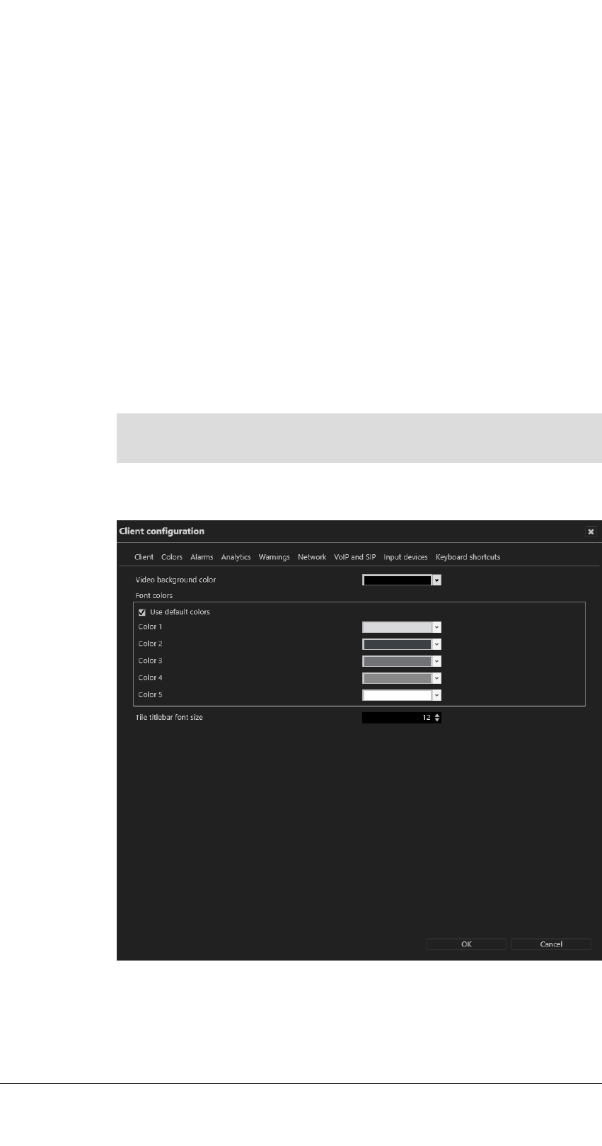
Fig. 3-4: Client configuration - Colors
n
Video background color is displayed around a video image if its aspect
ratio is not the equal to the aspect ratio of a view or tile.
n
Font colors. The default font colors can be changed
The user interface
3.1 The function bar
19 / 120

The user interface
3.1 The function bar
—
Color 1 on a dark background
—
Color 2 on a light background
—
Color 3 on a mixed background like the main menu
—
Color 4 on a mixed background like table headings
—
Color 5 on a video player border (black background)
n
Use default colors reverts to the default settings.
n
Tile titlebar font size: The font size in the title of layers or tiles can be
changed.
After confirming the changes, the Cayuga client must be restarted for the
changes to take effect.
Alarms
Fig. 3-5: Client configuration - Alarms
n
Alarm sequence to specify starting with more recent or older alarms
when processing the alarm list.
n
Stop low priority alarms when a new alarm is activated to stop low-pri-
ority alarms (priority 1-4) before the end of the predefined alarm interval
is reached.
High priority alarms cannot be stopped.
n
Restore minimized main window when an alarm occurs to restore the
main window in case of an alarm. If this option is not activated, the main
window will not be restored in case of an alarm.
n
Sequential alarm window to specify the desired number of rows and
columns to be displayed (see Adding a sequential alarm window, p. 35).
20 / 120

n
Maximum number of alarms in archive mode to specify the maximum
number of alarms displayed in archive mode (see Archive mode, p. 93).
After confirming the changes, the Cayuga client must be restarted for the
changes to take effect.
Analytics
Fig. 3-6: Client configuration - Analytics
The tracking data settings are defined as global settings in configuration
mode. They can be activated separately.
1. Select which tracking data should always be displayed in selected camera
images:
n
Objects
n
Classification
n
Counts
n
Object path
n
Rules
2. Select Always show selected tracking data to display tracking data also
in not selected camera images. This options needs more performance on
the client.
3. Configure the Maximum number of events in LPR mode when searching
for license plates. When the maximum is reached, a warning is displayed.
Increasing the number may lead to sluggish performance and longer
loading times.
The user interface
3.1 The function bar
21 / 120

The user interface
3.1 The function bar
After confirming the changes, the Cayuga client must be restarted for the
changes to take effect.
Warnings
Fig. 3-7: Client configuration - Warnings
n
Suppress warning about time difference to server to suppress a warning
if there are more than ten seconds of time difference between client and
server.
n
Suppress warning about low screen resolution to suppress a warning if
the screen used does not have a high enough resolution.
n
Suppress warning about MDS zone full to prevent a warning when the
storage depth limit of the multimedia database is reached.
n
Suppress warning about different streaming settings in configuration
mode to suppress the warning that recording losses can occur if there are
discrepancies between the settings for standard and alarm recording if
not using a second stream for alarm recording (see Video streams).
n
Delete entities without confirmation in configuration mode to delete the
entity (camera, time template, alarm, button, etc.) without receiving a
request for confirmation when you click Delete in configuration mode.
After confirming the changes, the Cayuga client must be restarted for the
changes to take effect.
22 / 120
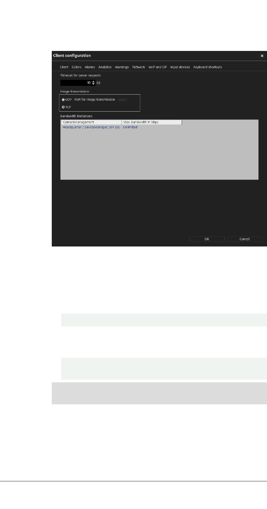
Network
Fig. 3-8: Client configuration - Network
The following options are available:
n
Timeout for server request to increase the time limit in seconds if the
server does not respond quickly enough.
n
Image transmission via the UDP or default TCP port. The UDP port is
freely selectable.
Select UDP only on 100% reliable network connections.
n
Bandwidth limitations to limit the bandwidth when accessing DeviceMan-
ager servers with a low-bandwidth connection to avoid overloading the
network.
It is not recommended to limit the bandwidth between a client and the
server. Frames will be dropped on a limited bandwidth.
After confirming the changes, the Cayuga client must be restarted for the
changes to take effect.
The user interface
3.1 The function bar
23 / 120

The user interface
3.1 The function bar
VoIP and SIP
Fig. 3-9: Client configuration - VoIP and SIP
The Cayuga client can act as SIP client to communicate with other clients or
voice units that support the SIP standard.
n
SIP base port number (the default is "5060").
n
Audio RTP port (the default is "7000").
n
Audio input device and audio output device. Regardless of this, incoming
calls go via the operating system's default audio output device.
n
Use echo and noise suppression to improve the sound quality.
n
Use microphone amplifier to increase the volume of the input device.
n
Specific settings for installation displays all existing Qognify installations.
n
Use keep-alive packages to adjust the intervals at which the client is to
log in to the SIP or VoIP server. The default value for Keep-alive interval
is 10 (s), and for Registration interval it is 3600 (s).
n
SIP user name and SIP password for the SIP server.
n
Participant name. The participant name is displayed as the called par-
ticipant in archive mode.
n
Registration server and Outgoing proxy: IP address of the SIP server.
A SIP server is required.
After confirming the changes, the Cayuga client must be restarted for the
changes to take effect.
24 / 120

Input devices
Fig. 3-10: Client configuration - Input devices
In this section of the client configuration, input devices like jog dials or joy-
sticks or key pads are configured.
The input device or the corresponding device drivers must be installed on
the Windows system before it can be configured.
The input device must be connected to the client computer before the cli-
ent starts. Otherwise it will not appear in the client configuration.
Select and display entities with buttons of a input device
1. Connect the device to the USB port of the client computer.
2. Select the device. The device functions are listed on the right-hand side
of the dialog box.
3. Enable Activate the device.
4. Enable the functions, e.g. virtual buttons or virtual sequences (see Con-
figuring virtual buttons or sequences of the Axis T8312 keypad, p. 26).
5. If necessary, activate the z-axis (depending on the hardware, usually avail-
able on joysticks).
6. Press the input device button to which you want to assign an action or
select the buttons number from the list.
7. Select the desired action (for example, when a certain button of the joy-
stick is pressed, a camera or a map is to be displayed in a certain window
of the Qognify configuration).
The user interface
3.1 The function bar
25 / 120

The user interface
3.1 The function bar
After confirming the changes, the Cayuga client must be restarted for the
changes to take effect.
Configuring virtual buttons or sequences of the Axis T8312 keypad
Using the Axis T8312 keypad, a camera can be displayed on a local Qognify
window or on a Qognify GmbH DisplayAgent (see DisplayAgent, p. 36). To
reduce the number of buttons that must be configured, each camera is
numbered. Refer to the manufacturer's documentation of the keyboard.
Fig. 3-11: Configuring virtual buttons or sequences of the Axis T8312 keypad
Only one of the following options can be assigned:
n
With the option virtual buttons, up to 1000 virtual buttons can be con-
figured for the Axis T8312 keypad to invoke up to 1011 actions.
n
The use of virtual sequences requires a correctly configured entity num-
bering (see Configuring the entity numbering). In surveillance or archive
mode virtual sequences can be started on the keypad (see examples
below).
For a detailed description of the Axis T8312 keypad functions refer to the
manufacturer's documentation.
1. Select Enable virtual buttons or virtual sequences.
2. With virtual buttons enabled, enter a value for the timeout (ms). Within
this period, the user must press the buttons to execute the configured
action.
3. For buttons or virtual buttons, select any button on the keyboard to dis-
play the assigned button in the list in the column “Number to display”
and define the action from the drop-down menu.
After confirming the changes, the Cayuga client must be restarted for the
changes to take effect.
The keys of the Axis T8312 keypad are assigned as follows:
n
First row:
—
F1: Local display
—
F2: Display agent
—
F5: Web page
n
Second row:
26 / 120

—
: Predefined layer
—
: Camera
—
: Tile
—
: Temporary layer
—
: Maps
n
Keypad:
—
0 - 9: Predefined sequences, buttons or virtual buttons 0...999
—
:Toggle between buttons 0...999 and virtual buttons
1000...1011:
n
Alt: 1001
n
: 1002
n
: 1003
n
: 1004
n
: 1005
n
: 1006
n
F1: 1007
n
F2: 1008
n
F3: 1009
n
F4: 1010
n
F5: 1011
Assigning virtual buttons or sequences
1. Press the key combinations on the keypad. The first key selects the
entity or number, the second number specifies the entity type or device
type, e.g.:
—
Pressing the keys 0 - F1 - 5 - displays camera number 5 on dis-
play (F1) number 0, the local main display.
—
Pressing the keys 3 - F2 - 1 - displays the predefined layer
number 1 on the display agent (F2) number 3.
—
Pressing the keys 1 - F1 - 5 - displays the layer number 5 (a
2x2 layer) on display (F1) number 1 (the local secondary display).
—
Pressing the keys 0 - F1 - 5 - - 4 5 - displays the cam-
era number 45 on display (F1) number 0 (the local main display) in
tile number 5.
For improved efficiency when assigning the virtual buttons or sequences,
the software “remembers” the previously assigned location, e.g. windows
or tiles.
Example
The keys 0 - F1 - 5 - have been assigned to display camera 5 on dis-
play 0 (see above). Entering next 6 - will display camera 6 on the
same display.
The user interface
3.1 The function bar
27 / 120

The user interface
3.1 The function bar
Restrictions and special cases
n
The jog dial and shuttle wheel are supported in archive mode for the Axis
T8312 keyboard.
n
The Videotec DCZ control unit is also supported with the following restric-
tions:
—
Only 32 of 38 buttons can be used.
—
Only the outer jog dial can be used in archive mode.
Keyboard shortcuts
Fig. 3-12: Client configuration - Keyboard shortcuts
Custom keyboard shortcuts can be defined for rearranging the client surface.
The following functions can be configured:
n
Toggle bottom control bar (default: (CTRL) + 6)
n
Toggle right control bar (default: (CTRL) + 7)
n
Shrink/Expand overview bar (default: (CTRL) + 8)
n
Shrink/Expand control bar (default: (CTRL) + 9)
n
Toggle all control bars (default: ESC)
n
Full screen (default: F10)
n
Push To Talk (default: (CTRL) + A)
For more shortcuts, see Shortcut keys, p. 113.
After confirming the changes, the Cayuga client must be restarted for the
changes to take effect.
28 / 120

Changing the language
Fig. 3-13: Changing the language
The following languages are available for the user interface and the help sys-
tem:
n
English
n
Czech
n
Danish (only user interface)
n
Dutch
n
French
n
German
n
Greek (only user interface)
n
Italian
n
Japanese (only user interface)
n
Norwegian (only user interface)
n
Polish (only user interface)
The user interface
3.1 The function bar
29 / 120

The user interface
3.1 The function bar
n
Portuguese (only user interface)
n
Russian
n
Romanian
n
Spanish
n
Swedish (only user interface)
n
Turkish
Additionally, you can define the user interface with a user defined lan-
guage (see "Technical_Guides_Qognify_Cayuga_R17_EN.pdf").
1. Select Change language from the File menu, and select the desired lan-
guage. If you select Windows default, the operating system language is
used.
2. Click OK to apply the selection, and restart the client.
Changing the password
You can change the user's password at any time, depending on the user
rights.
1. Choose Change password from the File menu.
Fig. 3-14: Changing the password - 1
30 / 120

2. Enter the password for the current user and click OK.
Fig. 3-15: Changing the password - 2
3. Enter the new password.
4. Click OK to apply the password.
Changing the profile
If multiple profiles are used (user profile, group profile, etc.), you can change
to a different profile. The profiles can be managed in configuration mode.
Fig. 3-16: Changing the profile
1. Select Change profile and the desired profile.
2. Click OK to confirm. The current profile is logged off, and the selected
profile is activated.
Changing the user
A different user can log on without closing the Qognify Cayuga client.
The user interface
3.1 The function bar
31 / 120

The user interface
3.1 The function bar
1. Select Change user from the File menu, and select the user.
2. Click OK to confirm your selection. The current user is logged out, and
the new user has to log in with a user name and password (see Login, p.
9).
Alternatively, the user can also be changed via the user icon in the function
bar (see Changing the user, p. 61).
Switching Cayuga installation
If you have installed multiple independent Qognify servers, you can connect
to a different Qognify server.
1. Choose Switch installation from the File menu. The login screen is dis-
played (see Login, p. 9).
2. Enter the server name or IP address and the user name and password.
The current installation is terminated, and the selected installation is star-
ted.
Installation manager
The installation manager manages and defines connections to multiple install-
ations (CoreServers). The current connection status is displayed.
Connecting to multiple installations can result in huge client and network
load.
When using bandwidth optimized archive playback from multiple install-
ations, make sure all installations are appropriately configured (see Band-
width optimization).
Fig. 3-17: Installation manager
n
Autoconnect (1): Activates or deactivates the client to connect to the
selected installation automatically.
32 / 120

n
Search (2): Allows searching for available installations
n
New (3): Allows adding a new installation
n
Delete (4): Removes the installation from the list
1. To edit a connection, click on the respective installation name.
2. To add an installation, select New (3) and edit the connection. The new
installation is not connected automatically.
3. To connect an available installation, enable Autoconnect (1).
Requirements
n
The server version on all servers to which a connection will be established
cannot be higher (newer) than the client.
n
All servers must support multi-installation login. A license must be avail-
able for Qognify multi-installation login.
Add an installation
1. Select Installation manager from the File menu, and select the desired
servers.
2. If the server is not displayed, add the installation by entering the install-
ation name, the IP address or host name, and the port number of the
server.
3. Click Add.
Reorder installations
Fig. 3-18: Reorder installations
1. Reorder the list of installations by selecting one object and dragging it to
the designated place in the list.
Disconnect and reconnect a Qognify installation
The color marker in the symbol indicates the connection state: a green dot
indicates a connected system and red dot stands for disconnected.
1. Click Autoconnect (1) to connect the client to the selected server auto-
matically when starting the client.
2. For manual connecting or disconnecting, click Connect or Disconnect (2).
3. To login to all installations with the same user name and password, select
Use local credentials for all installations. Optionally this option can be
activated on the login window (see Advanced login options, p. 12).
The user interface
3.1 The function bar
33 / 120

The user interface
3.1 The function bar
In this case make sure that the remote users are the same as the local cre-
dentials.
Edit Qognify installations
Changes the IP address, host name and the port number of the selected
server.
1. Click Edit (3) at the Qognify installation that you want to change. The
selected server is displayed at the bottom of the window.
2. Edit the installation name, the IP address or host name, and the port num-
ber of the server.
3. Click Apply.
Delete saved Qognify installations
Tidies up the list of Qognify installations most recently called by the client
(see Login, p. 9).
1. Click Delete (4) at the Qognify installation that you no longer want to be
available for selection.
2. To delete multiple installations at once, select the installations you want
to delete and click Delete selected objects.
View
The menu view displays the following options:
n
Adding a window
n
Adding sequential alarm window
n
Keep the aspect ratio
n
Borderless display
n
DisplayAgent
n
Video wall dispatcher
n
LPR master data editor
n
Count analysis
n
Access control data editor
The settings made in the View menu are stored locally and have to be
made on each client and for each Windows® login profile individually.
Exceptions are:
n
Settings for the LPR master data
n
Count analysis data
n
Access control data.
These data are saved on the server(s) by their corresponding services.
Adding a window
This function allows you to distribute the display of the work area to multiple
connected monitors.
34 / 120

1. Choose Add window from the View menu. A second window opens.
2. Move the window to the connected monitor. The client saves the setting
and makes it available when you log in again.
3. To use multiple connected monitors, repeat these steps.
Adding a sequential alarm window
In case of an alarm scenario, cameras that are defined as alarm cameras in an
active alarm scenario are displayed in a separate alarm window. The name of
the camera is displayed and the color of the image frame in the window cor-
responds to the color of the alarm scenario.
The camera images can be displayed either in row mode (one alarm per row)
or in continuous mode (multiple alarms per row).
Fig. 3-19: Adding a sequential alarm window
1. Select Add sequential alarm window to display all alarm related cameras
in a new dedicated window.
Keeping the aspect ratio
1. Select Keep aspect ratio to adapt the camera image to the layer window.
The camera image may appear distorted.
2. Deselect Keep aspect ratio to display the camera image with the original
aspect ratio.
The user interface
3.1 The function bar
35 / 120

The user interface
3.1 The function bar
Borderless display
1. Select Borderless display to hide the controls and the bars between the
camera images in layers with multiple cameras. If a camera is selected,
the border will be displayed.
2. Deselect Borderless display to hide the controls and the bars between
the camera images in layers with multiple cameras.
DisplayAgent
The Qognify DisplayAgent allows you to use standard PCs and monitors to
create a full-fledged remote-controlled video wall controlled by the video
wall dispatcher.
A video wall dispatcher is required to control a DisplayAgent.
Video wall dispatcher
The video wall dispatcher can control associated monitors dynamically. You
can drag and drop camera images, layers, maps and web pages to display
them on video walls, e. g. Qognify Display Agents or eyevis video walls.
LPR master data editor
In the LPR (license plate recognition) master data editor you can add and
delete license plates, as well as edit related data like driver's name, tickets,
history and notifications.
The license plate recognition must be configured in the Qognify VA
Administration Tool prior to usage.
Fig. 3-20: LPR master data editor
To manage license plates, the following options are available:
n
Creating a new license plate (1), see Creating a new license plate, p. 37
n
Editing a license plate (2), see Editing a license plate, p. 38
36 / 120
n
Deleting a license plate (3), see Deleting a license plate, p. 41
n
Displaying (4) and restoring (5) deleted license plates, see Displaying and
restoring deleted license plates, p. 42
n
Deleting a history (6), see Deleting a history, p. 42
n
Deleting a license plate permanently (7), see Deleting a license plate per-
manently, p. 42
n
Switching the view (8), see Switching the view, p. 43
n
Refreshing the view (9), see Refreshing the view, p. 43
n
Searching for a license plate (10), see Searching for a license plate, p. 43
n
Exporting and importing license plates (11), see Exporting license plate
master data, p. 43
License plates in the list (12) can be sorted and displayed by license plate
groups.
1. Click the arrow beside the name of the license plate group to close it.
2. Click the arrow again to open the license plate group again.
Creating a new license plate
Depending on the configuration, the window for entering new data is opened
automatically as soon as a license plate is recognized by the camera.
You can start the LPR master data editor from the "View" menu.
Fig. 3-21: Creating a new license plate
The user interface
3.1 The function bar
37 / 120

The user interface
3.1 The function bar
1. Enter the new license plate in the text box in the upper left if it is not yet
displayed.
2. Assign the license plate to a license plate group. License plate groups are
created in configuration mode in the license plate groups area.
3. Optionally, add descriptions for the license plate. The names and number
of text fields are defined in the server area in configuration mode.
4. Click OK to apply the settings.
Editing a license plate
1. Select a license plate in the list of the master data editor
2. Click Edit to change the details for the license plate.
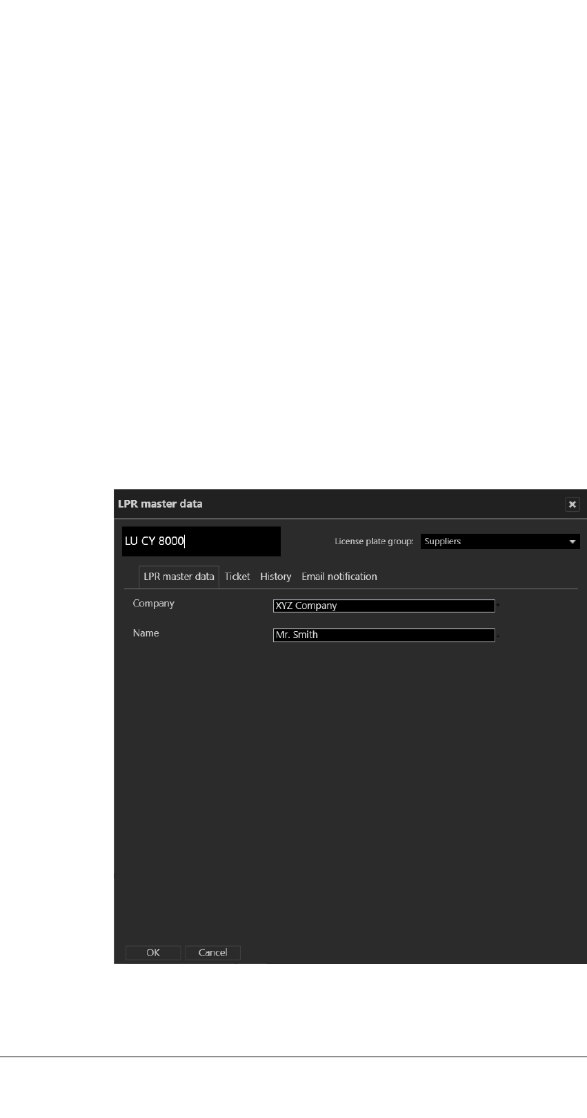
LPR master data
Fig. 3-22: LPR master data
1. Edit the license plate.
2. Click OK to apply the settings.
38 / 120

Ticket
Tickets define the validity time periods for certain licenses, e. g. a license
plate is allowed to pass a barrier at office time only.
Fig. 3-23: Ticket
1. Select a predefined Validity period for the license plate. The predefined
validity periods are displayed on the left.
2. To enter a specific time period, click Activate and enter the desired time
period. The status of the ticket is indicated in the LPR list by a different
font color and an icon. If a period is already defined, activation is no
longer enabled.
3. Click OK to apply the settings.
The user interface
3.1 The function bar
39 / 120

The user interface
3.1 The function bar
History
The history tab shows the initial configuration of the license plate and all sub-
sequent changes. The width of the columns can be adjusted to improve read-
ability.
Fig. 3-24: History
1. Click OK to close the window.
40 / 120

Email notification
You can send email notifications to certain recipients as soon as the vehicle
with the specific license number is recognized.
Fig. 3-25: Email notification
1. Enter the email addresses of the recipients separated by semicolons.
2. Enter the text for the email body. The numbers on the right are place-
holders for variables (i.e. license plate details) that are sent automatically.
3. Click OK to apply the settings.
Example
The text in the message "License plate [1] was recognized [4] at [5]." is sent as "License
plate LU CY 8000 was recognized 15.04.2010 at 4:25 pm." in the email.
Deleting a license plate
License plates can be removed from the list of valid license plates.
When removed from the list, the license plates lose their validity but are
not removed from the database. Therefore deleted license plates can be
restored.
The user interface
3.1 The function bar
41 / 120

The user interface
3.1 The function bar
1. Select a license plate from the list of the master data editor.
2. Click Delete to remove the selected license plate from the list. The
license plate is hidden.
Displaying and restoring deleted license plates
Fig. 3-26: Displaying and restoring deleted license plates
1. Click Show deleted entries to display the list including the deleted (i.e.
hidden) license plates.
2. Select the deleted license plate (displayed with grayed-out text), and
click Restore. The license plate is restored in the license plate list.
Deleting a history
If necessary, you can delete the history of a license plate (see History, p. 40).
1. Select the license plate whose history you wish to delete, and click
Delete history.
2. Click Yes to confirm the deletion.
Deleting a license plate permanently
To remove license plate from the database permanently, they first have to be
deleted (i.e. removed from the list).
License plates can only be permanently deleted by members of the admin-
istrator group.
1. Select the license plate that is to be permanently deleted. To delete mul-
tiple license plates, select the license plates while pressing and holding
the CTRL key.
2. Click Delete permanently, and confirm the deletion. The license plate is
permanently deleted.
42 / 120

Switching the view
1. Click Change view to display license plates grouped or ungrouped.
Refreshing the view
1. Click Refresh view to display any hidden license plates in the list.
Searching for a license plate
1. To search for a license plate in the list, enter part of the master data set
of the license plate into the search box (10). The search is started auto-
matically, and the result is displayed in the list.
2. Click the X in the search box to clear the search and display unfiltered
results.
3. When the configured maximum number of search results is exceeded,
the result can be exported as a CSV file(see Exporting license plate mas-
ter data, p. 43).
Exporting license plate master data
You can export the master data of selected license plates as a CSV file (a text
file with values separated by semicolons) in order to analyze or prepare it for
further import into databases.
1. Select the license plate whose master data you wish to export. To export
multiple license plates, select the license plates while pressing and hold-
ing the CTRL key.
2. Click Export (11) to export the master data as a CSV file (see Data fields
for export and import, p. 43).
Importing license plate master data
You can import the master data of license plates from a CSV file (a text file
with values separated by semicolons) .
1. Click Import (11) and select a CSV file with the license plate master data
to be imported (see Data fields for export and import, p. 43).
Data fields for export and import
The export and import file must contain the following data fields:
LicencePlate;re-
served;Group;...;AlwaysValid;ValidFrom;ValidTill;
Email;EmailText;ValidityName;modify
Field name Value Note
LicensePlate The license plate
reserved
Group Text Name of license plate
group as configured
The user interface
3.1 The function bar
43 / 120

The user interface
3.1 The function bar
Field name Value Note
If there is no entry the
group will be defined
as "unknown"
;;;;; Text Placeholders for user-
defined master data
fields
ValidFrom Date-time value Date/Time as Unix
date-time-value (mil-
liseconds since 1970)
ValidTill Date-time value Date/Time as Unix
date-time-value (mil-
liseconds since 1970)
AlwaysValid 1
"always valid" (same
values in fields Val-
idFrom and ValidTill
0
different values in
fields ValidFrom and
ValidTill
ValidityName negative value, e.g. -1 Always
positive value ID of related time tem-
plate
Modify 0
Value change is pos-
sible (see Importing
license plate master
data, p. 43)
Access control data editor
If the access control software "SiPass" is installed, the access control data
editor allows the editing of card holders' access data.
Card holders in the list can be sorted and displayed by license plate groups.
For information about working with the access control system, see "Tech-
nical_Guides_Qognify_Cayuga_R17_EN.pdf" or contact support (see Sup-
port).
1. Click the arrow beside the name of the card holder group to close it.
2. Click the arrow again to open the card holder group again.
Tools
This menu displays the following options:
44 / 120

n
Multiple export of image data (see Multiple export of image data, p. 49)
n
Write protection of recordings (see Removing write protection from
recordings of multiple cameras, p. 51)
n
Configure logo action (see Configuring a logo action, p. 52)
n
Status report for automatic image export (see Status report for automatic
image export)
n
Manual reference image comparison (see Manual reference image com-
parison, p. 53)
The Export Designer
The Export Designer in Cayuga configures the image export, i.e. adding
shapes to hide specific areas of the exported images to increase privacy or
defining a time range.
Creating a new export
Fig. 3-27: The Export designer
Defining the image or image sequence
1. In the Export Designer, select Create New from the Tools menu.
2. Select a camera from the list or search for a camera in the search box
above the list.
3. Move the timeline to the desired position. The corresponding frame is dis-
played. Zoom in or out of the timeline using the scroll wheel of the
mouse for more detail.
The user interface
3.1 The function bar
45 / 120

The user interface
3.1 The function bar
4. Click Add sequence (1) to set the starting point of an image sequence.
5. Drag the handle of the sequence delimiter to the right. This defines the
time frame for the export.
6. To mark only a single image for the export, click Add single image (2) and
drag the marker to the position on the timeline.
Adding shapes
Areas of the image or image sequence can be hidden in the export to prevent
information from being displayed in the export result, e.g. license plates or pri-
vacy sensitive objects.
Fig. 3-28: Adding shapes in the Export designer
1. To add a shape, open Shapes in the toolbar on the right and select a
shape. The selected shape is placed in the top left corner.
2. Drag the shape onto the image or sequence and resize.
3. Define the background color and transparency as well as the border
color and transparency.
4. Move the shape icon on the timeline to define the object to be masked
within the time range.
5.
To delete a shape from the image, select Delete next to the shape in
the list of “Current shapes”.
6. To delete a keyframe, select Delete keyframe next to the keyframe in
the list of “Keyframes”.
Adding a mask with "Click2Mask"
To confirm with privacy protection, persons in a scene can be masked auto-
matically before exporting. This feature is called “Click2Mask”.
To use "Click2Mask", the BVI server module must be installed. This fea-
ture requires 64bit mode and cannot be used with the package Cayuga
S50.
46 / 120

1. To add a mask, select a camera and add an image sequence.
2.
Open Shapes in the toolbar on the right and select Analyze . Cayuga
analyzes the sequence for a person. The resulting sequence is displayed
in the section "Keyframes".
3. If necessary, adjust the shape.
Defining the export settings
1. To define the export settings such as a password protection, open Export
settings in the toolbar on the right.
2. Enable the display of the camera time as additional information in the
image.
3. Enable the password protection if required, and set either a domain
default password or a user specific password.
4. Click the folder icon and select the export location of the file.
5. To add a variable to the export file name, click (x) and select the variable.
You can insert variables that will be included in the file name at the time
of export, such as:
—
Insert a variable for camera name: The name of the selected camera
is included in the exported file name.
—
Insert a variable for export time: The time of the export is auto-
matically included in the file name and can be defined by a
timestamp, the date, day, time, etc.
—
GUID:The global unique identifier of the file is included in the file
name.
6. Save the export settings.
7. Select Start export.
8. Open the Export Manager to open the exported file.
Resuming the image export
The user interface
3.1 The function bar
47 / 120

The user interface
3.1 The function bar
Resuming the export
Exports are queued in the export designer. The export settings can be
restored in case of failure. The settings file that has previously been con-
figured in the export designer is reloaded into the export queue.
1. In the Export Designer, select Resume from the Tools menu.
2. Optionally, reconfigure the export settings.
3. Start the export.
4. Open the Export Manager to open or delete the exported file.
Loading any file for export
Any setting that has been configured and saved can be loaded into the export
designer without the need to reconfigure. The setting will replace the current
configuration in the queue.
1. In the Export Designer, select Load from the Tools menu.
2. Optionally, reconfigure the export settings.
3. Start the export.
Deleting a marker
1. To delete a marker from the file, select the Delete icon in the item’s row.
Sharing a camera
Apart from a user with administrative rights, any user can share a camera if
the user rights are set.
If a sharing or receiving party is deleted or deactivated, or loses the shar-
ing or live view rights while sharing cameras, the sharing is stopped.
Fig. 3-29: Sharing a camera
48 / 120

Start sharing a camera
1. Activate the camera.
2. Select Share manager from the Tools menu.
3. Select Start sharing.
4. Select the user or group.
5. Click OK to confirm.
Stop sharing a camera
1. Select Share manager from the Tools menu.
2. Select Stop sharing.
Multiple export of image data
When exporting video recordings, the exported data are saved in encrypted
form and can then be played back on a computer without a Qognify install-
ation with the Qognify viewer. The Qognify viewer is found in the export dir-
ectory.
The setup files for the Qognify Viewer and the burning tool for burning the
exported video material onto a storage medium can also be found in the
folder "Tools" of the Qognify installation (see Anywhere Viewer, p. 115).
Fig. 3-30: Multiple export of image data
1. Select Multiple export of image data from the Tools menu.
2.
To open or close the list, click .
3. Select or deselect either all of the installed cameras or specific cameras.
4. If necessary, search the camera by entering the name in the search field
above the camera tree.
The user interface
3.1 The function bar
49 / 120

The user interface
3.1 The function bar
5. Enable the required parameters for export.
Information such as pre- and post-alarm duration, hardware and soft-
ware status, and the name of the VA module are exported auto-
matically.
—
Export standard recordings
—
Export alarm recordings
—
Including privacy mask settings: the feature is enabled by default if
the selected camera displays a privacy mask, otherwise it is disabled
—
Using a default password for protecting the exported data
—
Creating subfolders for users, camera name, and date and time of
export
—
Bandwidth limit definitions when exporting in a narrow-bandwidth
environment
—
Splitting of the exported files into multiple folders with a user-
defined folder size
6. Specify whether the image data is to be exported to the server or the cli-
ent by either selecting Export to server or Export to client.
Exporting image data to the server
1. Specify whether only standard recordings are to be exported or whether
alarm recordings are to be exported as well.
2. Specify the time period for the image data to be exported.
3. To secure the exported image data using the default password, select
Use default password.
4. If you want to use your own password instead of the default password,
enter this password and repeat it. Optionally, use the default password.
The default password is set in configuration mode in the DeviceManager
(DM) section.
5. Click Select and specify the location of the exported image data.
If the selected cameras are connected with multiple DeviceManagers,
make sure that the export path is accessible by each related DeviceM-
Manager.
6. To store the exported image data in separate folders by user, camera
name and time of export, select Create subfolders for user, camera
name and time of export.
7. To carry out the export at a specific time, select Select time for export,
and then specify a date and time for the export.
8. To split the exported files for storage on multiple data carriers such as
CD-ROMs or DVDs, select Split export into multiple folders.
The minimum size of the file is 100 MB.
9. Select the desired folder size according to the export medium (e.g. CD,
DVD, Blue-ray disc).
10. Specify the maximum size of the image file.
11. To carry out the export immediately, click Export.
50 / 120

During the export process, the Qognify viewer installation file and a program for burning
to CD / DVD (Totally Free Burner) are copied to the export folder as well. This allows the
files to be run on a computer without a Qognify installation with only the Qognify viewer
installed. The Qognify viewer will import the files and display them as separate time inter-
vals.
Exporting image data to the client
1. Make sure that a temporary folder for image data export to the client is
configured and available.
2. Specify if only standard recordings are to be exported or if alarm record-
ings are to be exported as well.
3. Specify the time period for the image data to be exported.
4. To secure the exported image data using the default password, select
Use default password.
5. If you want to use your own password instead of the default password,
enter this password and repeat it. The default password is set in con-
figuration mode in the DeviceManager (DM) section.
6. Click Select, and specify the storage location of the exported image data.
If you know the folder path, you can also enter it in the text box directly.
7. To store the exported image data in separate folders by user, camera
name and time of export, select Create subfolders for user, camera
name and time of export.
8. If the image data is to be exported to a client that has only a low-band-
width connection, select Use bandwidth limit and specify the bandwidth
limit.
9. To store the exported image data in folders of approximately the same
size as the expected file size, select Split export into multiple folders
and specify the folder size and maximum size of the image file. Image
data that exceeds the specified size is split into multiple files so that they
can be stored on data carriers such as CD-ROMs or DVDs.
10. To carry out the export immediately, click Export.
During the export process, the Qognify viewer installation file and a pro-
gram for burning to CD/DVD (e.g. Totally Free Burner) are copied to the
export folder as well. This allows the files to be run on a computer
without a Qognify installation with the Qognify viewer. The Qognify
viewer will import the files and display them as separate time intervals.
Viewing exported files
1. For viewing the exported files, start the “VMS_PortableViewer”. The
Viewer allows opening an viewing the exported files without modi-
fication and without installation of Qognify Cayuga.
Removing write protection from recordings of multiple cameras
The write protection of recorded image data can be deleted (see Write pro-
tection, p. 99).
The user interface
3.1 The function bar
51 / 120

The user interface
3.1 The function bar
Fig. 3-31: Removing write protection from recordings of multiple cameras
1. Choose Write protection of recordings from the Tools menu.
2. Select the cameras to be checked to ascertain whether there is a write-
protected recording area.
3. Click Start query to display any write-protected recordings of the selec-
ted cameras.
4. Select the areas in which write protection is to be removed from record-
ings.
5. Click Remove write protection.
6. Close the window.
Configuring a logo action
Logo action allows you to specify which layer is to be displayed when you
click the Qognify logo at the top of the screen.
Fig. 3-32: Configuring a logo action
52 / 120
1. Select Configure logo action from the Tools menu.
2. Select the defined layers from the drop-down list. The layers are saved in
the configuration menu.
3. Click OK to confirm.
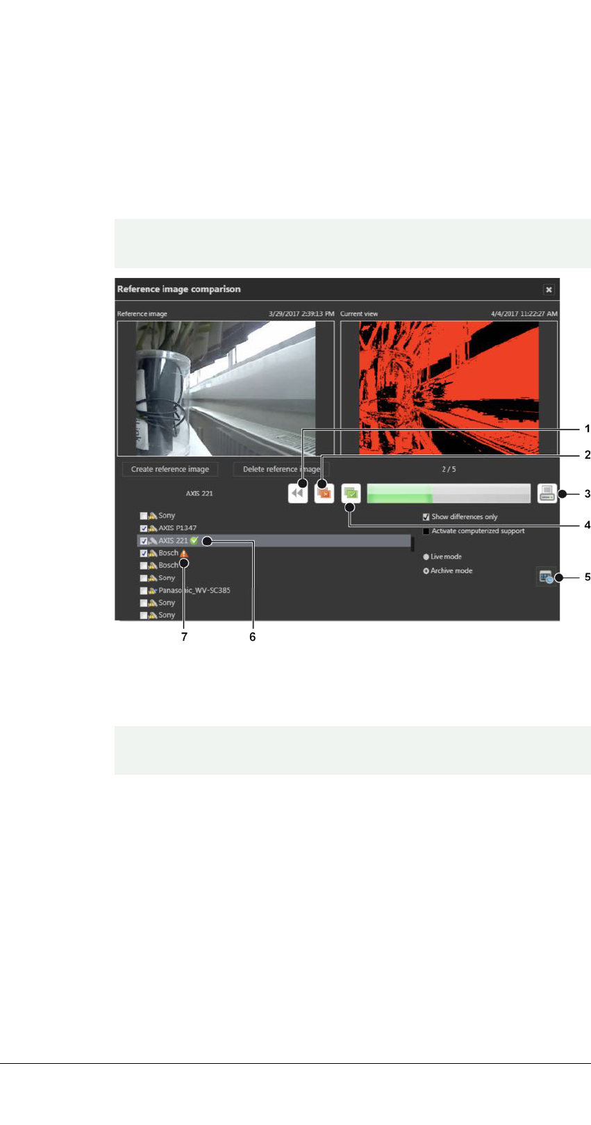
Manual reference image comparison
To create reference camera images and compare camera images, the user
must have the rights to see live images in surveillance mode.
Fig. 3-33: Manual reference image comparison
The manual reference image comparison helps detect changes in the static
object.
Mobotix cameras are only supported for Motion JPEG. Reference Image
comparison does not work on images from fish-eye cameras.
1. Select a camera from the list and click Create reference image. The cur-
rent camera image will be used as reference image. The current view dis-
plays the actual live image of the camera or an archived image.
2. To delete a reference image, select the camera from the list and click
Delete reference image.
3. Select the camera and check both images for changes.
4. Click Deviations (2) to reject and mark the images as not identical. The
red icon (7) is displayed behind the camera name.
5. Click Congruence (4) to accept mark the images as identical. The green
icon (6) is displayed behind the camera name.
The user interface
3.1 The function bar
53 / 120

The user interface
3.1 The function bar
6. If the changes are difficult to see, select Show differences only. The
changes detected by the image processing software will be displayed as
highlighted areas in the current view. If no changes are detected, the cur-
rent view turns black.
7. Deselect Show differences only to return to the actual camera image.
8. Select Activate computerized support to display a threshold scale. Move
the pointer on the scale to change the threshold values. This changes the
threshold values of the current image and helps discern possible changes
in the image.
9. Select Live mode or Archive mode. When Archive mode is selected, the
reference image can be compared to a recorded image.
10. Click Calendar (5) and select a date and time of the archived image.
11. To print a report of the results, click Print (3). Also see Printing the ref-
erence image comparison report, p. 54.
Printing the reference image comparison report
Fig. 3-34: Printing the reference image comparison report
1. In the print report dialog, select Show difference images to print the cur-
rent views with the differences highlighted.
2. Select Show difference as percent to print the percentage of the detec-
ted differences within each image.
3. Select Show rejected cameras only to print the report without the accep-
ted cameras.
4. Enter the User name and add a Comment, if necessary.
5. Click Print report.
Info
The menu Info displays information about the system and both procedures to
obtain a license for Qognify Cayuga R17. The installation must be activated
54 / 120
within 30 days. This requires sending an automatically generated activation
key, the product ID, to Qognify.
This menu displays the following options:
n
Activating the software
n
Showing information about the software
Activate the Qognify Cayuga license online
The product is activated online to personalize a license or download a license
file.
Online activation requires a connection to the internet.
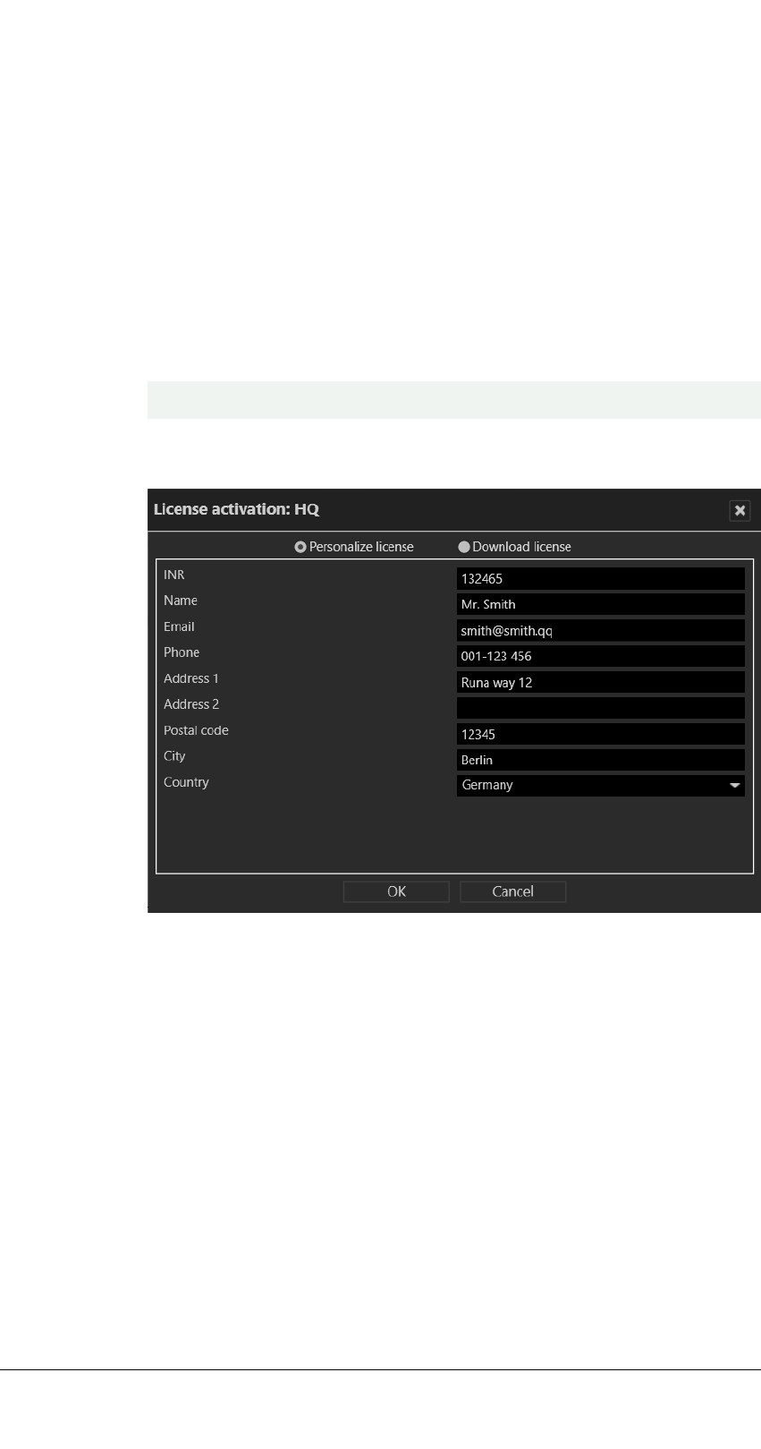
Personalize a license
Fig. 3-35: Personalize a license
1. In the Info menu, select Activate product.
2. Select Online.
3. Select Personalize license if you want to register it with your user data,
and the license has not yet been registered.
4. Enter your installation number (INR) and user details.
5. Click OK to confirm your entries. The client connects to the Qognify
registration server and transfers the license key to the computer.
The user interface
3.1 The function bar
55 / 120
The user interface
3.1 The function bar
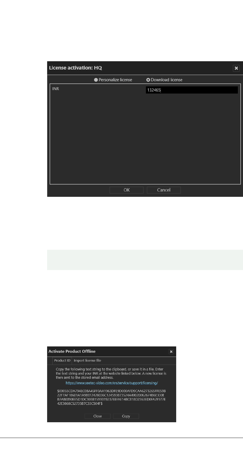
Download a license
You can download a new license file if an update has been carried out and the
license is required again.
Fig. 3-36: Download a license
1. Select Download license.
2. Enter your installation number (INR).
3. Click OK to confirm your entries. The client connects to the Qognify
registration server and transfers the license key to the computer.
If the product ID has changed (e.g. due to changes to the server hard-
ware), contact the Qognify support.
Activate the product offline
If the client has no internet access, activate the client by first applying for a
license via email. After receiving the license file per email, it has to be impor-
ted.
Applying for a license
56 / 120
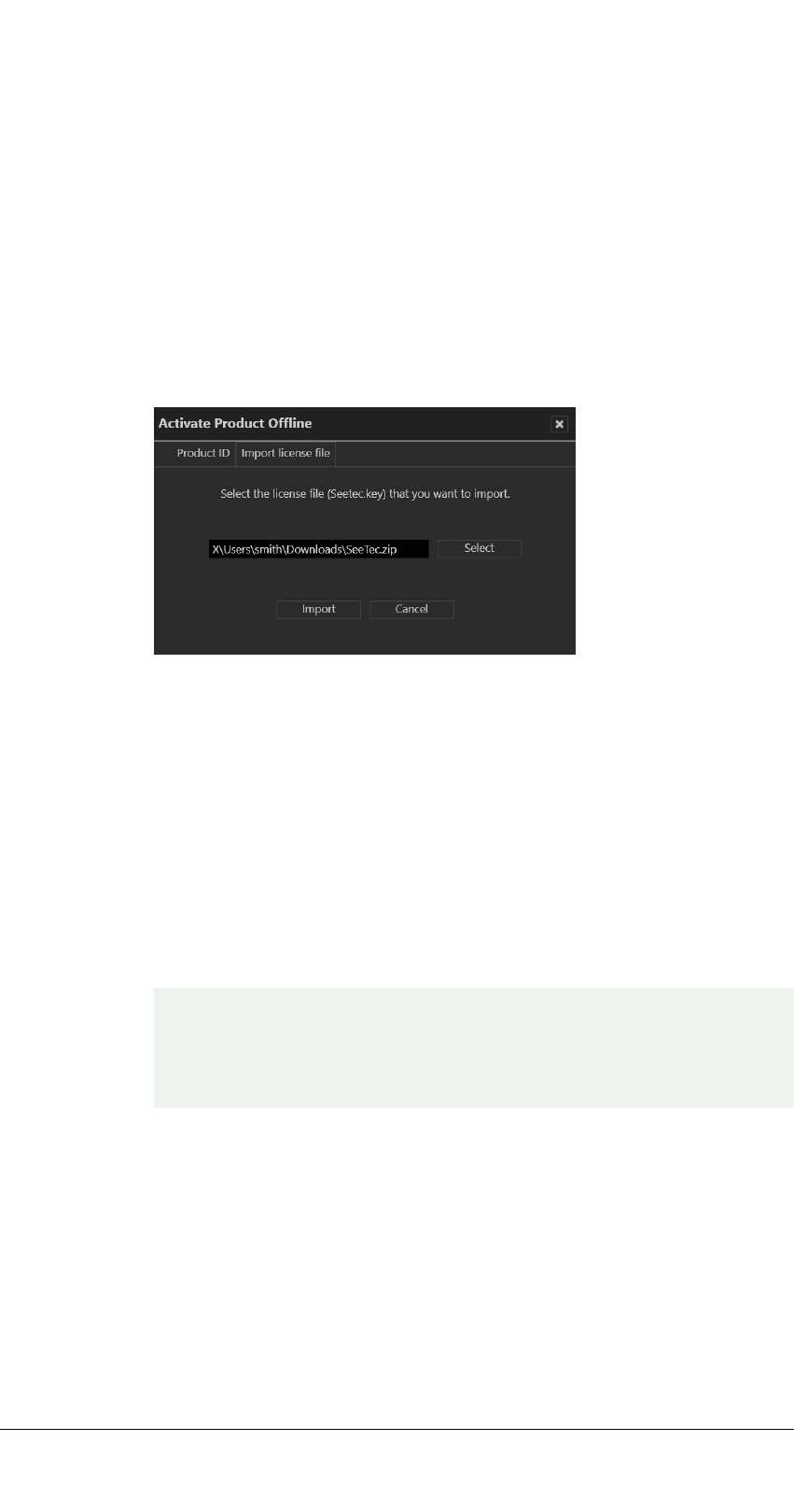
Fig. 3-37: Applying for a license
1. In the Info menu, select Activate Product.
2. Select Offline.
3. Select the tab Product ID. The software creates a unique product ID.
4. Click Copy to copy the displayed product ID to the clipboard.
5. Open the Qognify website and navigate to "Support" and "Licensing".
6. Select "New license code".
7. Enter your product ID and the other information requested there. You
will receive the license file by email.
Importing a license file
Fig. 3-38: Importing a license file
1. In the Info menu, select Activate Product.
2. Select Offline.
3. Select the tab Import license file.
4. Click Select and navigate to the storage location of the license file.
5. Select the license file. Upon import, the zipped file will be decompressed
automatically.
6. Click Import to use the license key.
Show license
A test license will be installed during installation and is valid for 30 days.
A demo license is valid until the displayed date. If no valid license is avail-
able, login is not possible. For further questions, contact the Qognify sup-
port.
1. In the Info menu, select Show information.
2. Select Show license. Information on the license is displayed in three tabs.
3. Select tab Overview to see general information of the product, e.g. the
INR (Installation Number), SMA (Software Maintenance Agreement), the
validity period of the license (if it is a demo license).
The user interface
3.1 The function bar
57 / 120

The user interface
3.1 The function bar
Fig. 3-39: Show license - overview
4. Select Features to see the features activated by the installed license file.
Fig. 3-40: Show license - features
5. Select Modules to see how many modules like cameras (devices), servers,
analytics channels etc. are activated by the installed license file.
58 / 120
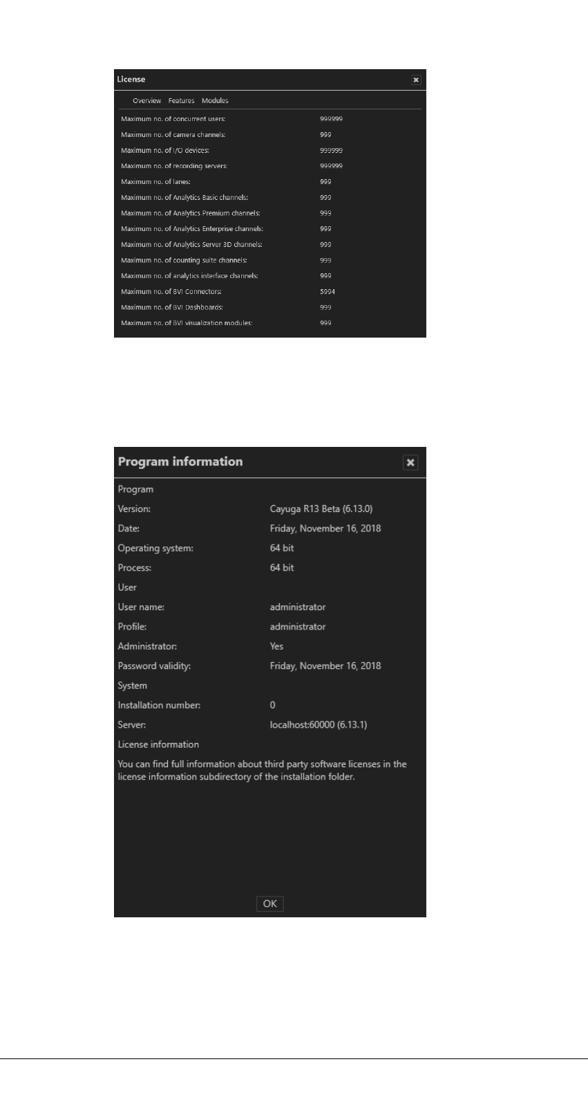
Fig. 3-41: Show license - modules
Show program information
Fig. 3-42: Show program information
1. Select Show program information from the Info menu. The information
on items such as the program version, current user and profile and also
validity of password is displayed.
The user interface
3.1 The function bar
59 / 120

The user interface
3.1 The function bar
Show system information
Fig. 3-43: Show system information
1. Choose Show system information from the Info menu. The information
on items such as the Core Service Main, the numbers of activated
DeviceManagers, video sources (cameras) is shown.
2. Click Copy to copy the system information to the clipboard. You can
paste the data from the clipboard to your email program to send it to sup-
port.
Help
The help menu displays the following options:
n
Online help
n
Start problem recording
n
Display help icons
Online help
Starts the help system on the starting page. In addition, there are also links
for accessing specific topics directly from the various controls and dialog
60 / 120

boxes. The system automatically checks for current versions of the online
help system. The user is notified if the installed version is not up-to-date.
When starting the help system for the first time, you may be prompted by
the browser to activate ActiveX or allow JavaScript. The help system will
not function properly, if those services are blocked.
Start problem recording
If problems occur during operation, you can use the "Start problem record-
ing" function to record, comment on and save them. The "Problem Steps
Recorder" is part of the operating system.
1. Select Start problem recording from the Help menu.
2. Select Start recording and carry out the steps that led to the problem.
3. As soon as you have carried out these steps, stop recording.
4. If you want to add a comment to the recording, click Add comment (e.g.
the time, behavior of the client and devices, etc.).
5. Specify where the file is stored.
Display Help icons
1. The help icons are small gray circles with question marks in the program
components that lead directly to the applicable section of the Online
help system.
2. Choose Display Help icons from the Help menu. The function is activ-
ated (check mark) or disabled (no check mark).
Changing the user
The user interface displays the current user in the function bar.
Fig. 3-44: Changing the user
1. Click the user icon in the function bar.
2. Click Change user to log on to the server as another user. Alternatively,
change the user via the "File" menu (see Changing the user, p. 31).
3. Click Log out to log out the current user from the server.
The user interface
3.1 The function bar
61 / 120

The user interface
3.2 The mode bar
3.2 The mode bar
Fig. 3-45: The mode bar
The mode bar allows you to switch between display modes.
n
Surveillance mode (1). After login, the system
starts up in surveillance mode (see Sur-
veillance mode, p. 65). The number of alarms
and system events that have occurred are
indicated by a number in the icon. Addi-
tionally, the number of alarms and system
events are indicated by a number in their
respective tab in the alarm list (see Alarm list
and system messages, p. 87).
n
Archive mode (2): Archive mode manages
and displays recorded image data and search
for alarm events (see Archive mode, p. 93).
The number of export operations that have
occurred is indicated by a number in the
Archive icon.
n
Report mode (3). Report mode displays a list
of the events that have occurred (see Report
mode, p. 109).
n
Configuration mode (4). Configuration mode
manages and configures the video sources,
users and locations.
n
LPR mode (5). LPR mode is used for license
plate recognition in the image data of the cor-
responding cameras.
3.3 The control bar
The control bar contains the tabs required, depending on the mode, for con-
trolling the display or for configuration. You will find descriptions of the tabs
in the sections describing each mode. Tabs cannot be moved. They remain
anchored in position on the control bar.
62 / 120
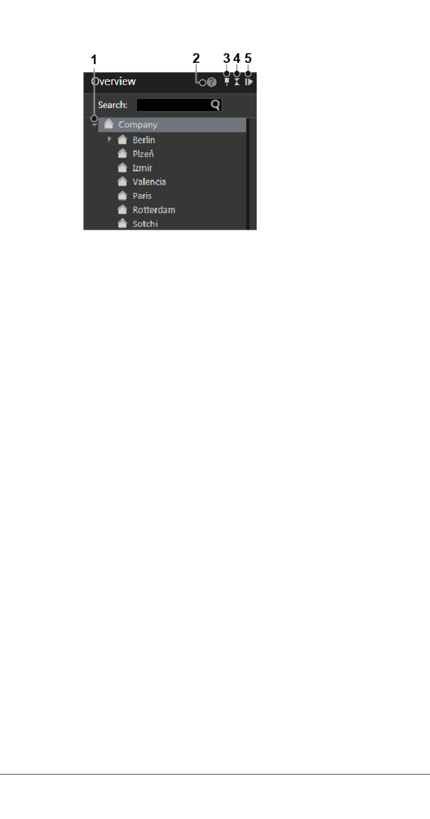
Fig. 3-46: The control bar
Displaying items in tree view
1. Click the triangle (1) on the left side of the upper item in the tab to dis-
play or hide the items beneath.
Opening the context sensitive help
1. Click Help (2) to open the online help in the default web browser. The
web browser can be selected in the client configuration (see Client, p.
18). The online help can also be started from the help menu (see Help, p.
60).
Pinning the control bar
By default the control bar is always visible (pinned). An auto hide option is
available.
1. Select the pin (3) to activate the auto hide function. In this state the con-
trol bar minimizes automatically to the right when the cursor moves
away from the control bar. As soon as the cursor moves over the min-
imized control bar it appears automatically.
2. Select the pin (3) again to deactivate the auto hide function. In this state
the control bar is always visible (default).
Minimizing and maximizing a control
1. Click the double triangle (4) to minimize a control to the top of the con-
trol bar.
2. Click the double triangle (4) to maximize a control.
Minimizing and maximizing the control bar
1. Click the gray triangle (5) in the upper-right corner of a control to min-
imize the control bar to the right. The size of the main window increases.
2. Click a gray triangle (5) on the minimized control bar to maximize the
control bar.
The user interface
3.3 The control bar
63 / 120

The user interface
3.4 Search
3.4 Search
Qognify Cayuga provides mode-specific search and query functions:
n
Searching in surveillance mode (see Searching in surveillance mode, p. 91)
Searching for items in the control bar is also available in Archive mode
and LPR mode.
n
Searching for alarms in archive mode (see Searching for alarms, p. 100)
n
Searching (query) in report mode (see Filtering the query, p. 109)
n
Searching in configuration mode
n
Searching (query) in LPR mode
64 / 120

65 / 120
Surveillance mode
Surveillance mode allows live images, web sites, maps, layers, alarms and
patrols to be displayed and PTZ cameras and other peripherals, such as door
openers, that are to be controlled (see The user interface, p. 15).
1. To change to Surveillance mode, click Surveillance mode on the mode
bar.
Camera operation
You can handle the functions of the camera using the control bar (see Camera
image controller, p. 72) or using the Control (see Control, p. 80).
To operate a camera, select the camera in the work area.
You can recognize a standard recording by a green dot below the lower right
edge of the camera image in surveillance mode. You can recognize an alarm
recording by a red dot below the lower right edge of the camera image.
If there is no recording, a black square instead a red or green dot is displayed.
Tabs
The tabs allow you to open and close the layers (see Work area, p. 66).
Control bar
The control bar allows you to perform the following actions:
4

Surveillance mode
4.1 Work area
n
Move the selected PTZ cameras and change the image detail (see PTZ con-
trol, p. 80)
n
Perform actions using buttons (see Buttons, p. 83)
n
Carry out patrols (see Patrol, p. 84)
n
Use the optionally installed communication options (camera and audio)
(see Audio, p. 85).
n
Call dispatcher mode (if installed, see Video wall dispatcher, p. 36). The dis-
patcher mode is switched on and off via the View menu.
n
Select the cameras created for each location (see Overview, p. 79)
n
Search for specific installed cameras
4.1 Work area
The work area is the main window for displaying tiles with items such as cam-
era images or maps (see The user interface, p. 15) . The work area displays up
to 64 tiles at the same time. The tiles can be arranged in different ways:
n
Evenly as a grid
n
With a main layer and smaller layers (e.g. "layer with focus tile")
Alarm notification ("Toast notification")
Fig. 4-1: Alarm notification ("Toast notification")
Depending on the setting, alarms and system messages are displayed as they
occur in a separate message window (alarm notification) at the bottom of the
screen. For further information, see the Alarm messages, p. 88.
66 / 120

Creating layers
Layers can be set in the layer area in configuration mode. Temporary layers,
which are only available for the user and are not saved, can optionally be com-
bined.
In some layers, the available objects such as cameras or maps can be assigned
to any tile in the work area.
1. Drag the desired layer from the Overview control to the work area..
Optionally, click Layer menu on the function bar (see The function bar, p.
16) and select Add layer. You can select the desired number of tiles or
create a user-defined layer. Or select Load local layer to load a previous
saved user defined layer. The selected layer is displayed right to the layer
menu icon in the tab selector.
2. Click the cross on the tab to close this layer.
3. Drag the selected object to the desired tile in the work area. To move an
object in the work area, drag it to the tile in which it is to be displayed. If
there is an object there already, it is moved to the previous tile of the
moved object.
4. Select Open layer in secondary window to display the new layer on a
second screen (see View, p. 34).
5. Select automatic layer switching and the desired interval to switch auto-
matically between the opened layers after a certain interval.
Automatic layer switching is stopped in the event of an alarm scenario
and automatically resumed after an alarm.
Setting the viewing mode on multiple windows
The viewing mode feature is available when using multiple client window to
keep the windows in different states. If multiple displays are connected to the
client, client windows can be distributed to them. The viewing mode of each
window can be set separately, so displays can remain in surveillance mode
even if the main display is switched to another mode (e.g. archive mode or
configuration mode).
Fig. 4-2: Viewing mode icon "Keep window in surveillance mode"
1. Switch to surveillance or archive mode and drag the required camera
view onto the secondary window. The drag & drop feature works
between surveillance and archive mode and vice versa.
2. On the secondary window, select Keep window in surveillance mode.
The camera view on the secondary window will remain in surveillance
mode with live image even if the primary window is switched to another
mode.
3. To remove the viewing mode on the secondary display, select the mon-
itor icon again.
Surveillance mode
4.1 Work area
67 / 120

Surveillance mode
4.2 Sequential alarm window
4. When clicking on the monitor icon on the secondary window after switch-
ing the viewing mode on the primary window, the last live image view
will be restored on the secondary window.
4.2 Sequential alarm window
The settings for the sequential alarm window are defined in the View menu
(see Adding a sequential alarm window, p. 35).
Fig. 4-3: Sequential alarm window
1. To switch to the sequential mode, click (1). The alarms will be displayed
in a single row. If the number of alarm cameras exceeds the number of
columns defined, the remaining alarm cameras will be ignored.
2. To switch to continuous mode, click (2). If the number of alarm cameras
exceeds the number of columns defined, the additional cameras will be
added in the row below.
4.3 Click-2-Track
A person or object that moves across different camera views can be followed
even without specifying the camera name of the following view. Instead, the
person or object path is defined in surveillance mode by activating the area
covered by the adjacent camera.
This feature is also available in archive mode (see Click-2-Track, p. 96) and
can be invoked with the mini archive player (see Mini archive player, p. 73).
This feature requires an appropriate license and is not included in the
standard package.
68 / 120

Fig. 4-4: Click-2-Track in surveillance mode
1. To start Click-2-Track, select the tile and click on the camera options.
2. Select Activate.
3. Select the region on the image where the person or object moves to. The
linked camera image is displayed in the preview inset.
4. To bring the image in the inset into the tile, click on the preview. Click-2-
Track remains activated.
History
Once multiple camera regions have been visited, the history buttons are act-
ive. They are used to navigate forward and backward through the history of
this tile, since each tile has a separate history.
When using the Click-2-Track history in surveillance mode, the tile is
switched to mini archive player.
Preview cameras shown while in mini archive mode display the same time
as the mini archive player.
Surveillance mode
4.3 Click-2-Track
69 / 120

Surveillance mode
4.4 Custom layers
4.4 Custom layers
When working in surveillance mode, custom layers can be added and stored
locally. Unlike layers configured in the configuration mode, the custom layers
can be defined and deleted by the user.
Fig. 4-5: Custom layers
1. Select the Layer in the top bar of the surveillance mode bar.
Opening and closing a layer directly in a custom layer
1. Double click on a window to enlarge the layer.
2. Double-click on an enlarged layer to reduce its size to the preset state.
70 / 120

Adding alayer
1. Click Add layer and select the required arrangement of the layer fields
or select a user-defined arrangement of rows and columns. The new
layer is displayed.
2. Drag the camera views from the control bar into the fields and click Save
layer as local layer to save the new layer view for the current user on
the client.
Expanding a layer
1. Click Add layer and select the required arrangement of the layer fields
or select a user-defined arrangement of rows and columns. The new
layer is displayed.
2. Click Edit layer and select any optional layout the provides additional
tiles (unavailable tiles are disabled). The current layer tab is set to the
new layout.
Opening a layer in the secondary window
1. Click Open layer in secondary window to move the new layer to a sec-
ondary window if a second display is available.
Changing a layer automatically
1. Click Automatic Layer change and select a time interval after which the
next open layer is displayed.
Loading a local layer
1. To open an existing layer, click Load local layer and select the layer.
Deleting local layers
1. To delete a locally saved layer, click Delete local layers.
2. Select the layer(s) to be deleted and click Delete layers.
Surveillance mode
4.4 Custom layers
71 / 120

Surveillance mode
4.5 Camera image controller
Closing layers
1. To close a single layer, click Close layer.
2. To close all open layers, click Close all layers. Unsaved layers will close
without further notice.
4.5 Camera image controller
You work with the images of the connected and configured cameras directly
in the camera layer in the work area.
These functions refer only to the control options offered by Cayuga.
Camera image control icons
PTZ cameras are operated using the Control, p. 80.
Fig. 4-6: Camera image control icons
n
Zoom (1). Enlarges the image detail with the help of the digital or optical
zoom function.
—
The image detail is enlarged or reduced in size using the scroll wheel
on the mouse.
—
You can move the zoomed image by holding down the middle mouse
button.
—
Optionally, when drawing a rectangle in the image while pressing the
left mouse button, the enclosed area will be zoomed into.
—
PTZ cameras can be operated using the controller or a connected joy-
stick. For some PTZ cameras, zooming into a defined rectangular area
in an image by optical zoom is enabled.
Optical zoom is only possible if supported by the camera model.
n
PTZ (2). Moves the image detail in the layer. The image detail can be
changed by clicking and moving the mouse pointer in the image (see Cam-
era image controller, p. 72). PTZ cameras can be operated using the con-
troller or a connected joystick.
72 / 120

n
Layer options (3). Shows additional options:
—
Tracking data: Displays the specified rules and detected for this cam-
era (e.g. tripwires) in the view.
—
Display statistics: Displays statistical data on the image stream
between the camera and the DeviceManager server and between the
DeviceManager server and the client (see Camera image statistics, p.
76).
—
Activate privacy masking: Activates or disables privacy masking. The
settings for the camera are made in configuration mode in the Cam-
eras area.
—
Deselect: Deselects the selected camera.
—
Rotate Image (180°). Displays the camera image rotated by 180° rota-
tion when the original camera image is displayed upside-down.
—
Open in new tab: Displays the camera in a separate layer.
—
Open in side window: Displays the camera in a separate layer in the
first secondary window.
—
Close: Closes the active layer
n
Mini Archive mode (4). Shows the recordings of the selected interval (see
Mini archive player, p. 73).
—
The interval can be between 5 and 60 seconds and is displayed or
selected by clicking the icon.
—
When selecting Jump to time you can easily jump to a certain time
point of the recording.
n
Audio mode (5). Controls the cameras' audio feature (volume / mute / per-
manent on)
n
Export (6). Exports the current still image (video frame) as a JPEG file or
prints the still image displayed.
n
Tile on 1x1 layer (7). Enlarges the tile so that it fills the full screen of the
work area. This option is only available when the tile is not in full screen
display.
n
Camera lock (8): Locks the camera for the user. Clicking the icon again
releases the camera for other users. The camera lock function must be
enabled in the Users settings in configuration mode.
n
REC (9). Starts and stops manual recording. A red button on the right indic-
ates if an alarm recording has started.
n
Recording status (10): Indicates the recording behavior for the camera. A
green dot stands for standard recording , a red dot stands for alarm
recording . Just the black background stands for no recording.
n
Positions (11). Indicates the preset positions of the selected camera. The
camera positions are set in configuration mode in the Cameras area. To
control the set positions, see Control, p. 80.
Mini archive player
The mini archive player allows control of the playback from a selected cam-
era. More extensive archive functions are available in archive mode (see
Archive mode, p. 93).
Surveillance mode
4.5 Camera image controller
73 / 120

Surveillance mode
4.5 Camera image controller
Fig. 4-7: Mini archive player
The mini archive player provides the following functions:
n
Fast rewind (1): Click once to play the recording backwards at double
speed. Click twice for four times the speed.
n
Previous frame (2): Jumps to the event's previous frame or JPEG image.
n
Play backward (3): Plays the archived video stream in reverse chro-
nological order.
n
Pause (4): Pauses the playback.
n
Play forward (5): Plays the archived recording in the correct chronological
order.
n
Next frame (6): Jumps to the event's next i-frame or JPEG frame.
n
Fast forward (7): Click once to play the recording forward at double
speed. Click twice for four times the speed.
n
Calendar (8): Opens a calendar window in order to jump to a specific
point in time.
n
Add bookmark (9): Adds a bookmark to the current frame (see Working
with bookmarks, p. 102).
Manual alarm recording
Alarm recordings can be started and stopped manually by the user who has
started them. Additionally, bookmarks can be added to the recording. Book-
marks can be used for the search in archive mode (see Searching for alarms,
p. 100).
Starting manual alarm recording
1. Click the REC button (10, see above). A red bell on the right indicates
whether alarm recording has started.
To prevent unlimited recording, the maximum post-alarm duration
must be specified in configuration mode in the camera settings.
74 / 120

2. Optionally, click Add bookmark. A bookmark information window is dis-
played.
3. Enter the name and a short description of the bookmark.
4. Click OK to add the bookmark to the recording.
Stopping manual alarm recording
1. Click the REC button again. The recording is stopped.
2. Optionally, add an additional bookmark.
Swiveling the camera in the image
The camera can be moved in pan and tilt mode in the image. Swiveling the
camera sideways is called "panning" (creating a panoramic effect), whereas
swiveling the camera up and down is called "tilting".
1. Click PTZ (2). A red cross appears in the center of the image.
2. Click a point next to the cross. The distance of the point you click from
the center of the cross determines the speed of the swivel operation in
the relevant direction.
3. If you like, you can activate the zoom function of the PTZ camera. Using
the mouse wheel, zoom in or out of the image.
4. Click PTZ again to deactivate the swivel function in the image.
Surveillance mode
4.5 Camera image controller
75 / 120

Surveillance mode
4.6 Maps
Camera image statistics
Fig. 4-8: Camera image statistics
The camera image statistics show information about the following details:
n
The video images which are rendered by the client. The Decoding (fps)
should be similar to the Rendering (fps),
n
The video images which are recorded on the server,
n
The quality of the audio stream,
n
The network quality. The Packet loss (%) ratio as well as the Max. Jitter
(ms) value should be as low as possible. High values indicate network prob-
lems. E. g. jitter may be caused by electromagnetic interference and
crosstalk with carriers of other signals.
4.6 Maps
A map shows an area to be monitored. In configuration mode it is added to
the software as a simple graphic. The various cameras and other functional
icons are then integrated into this graphic. The map can thus show a variety
of different parts of the company: from the company site to fully automated
production lines.
The map shows the cameras that the user can only.
76 / 120

If a camera has failed (due to power failure, no connection to the net-
work, etc.), the camera icon is shown as a yellow warning sign.
Fig. 4-9: Maps
1. Click Digital zoom (1) to activate the zooming function for the map.
2. Zoom the map detail by turning the mouse wheel while the mouse
pointer is on the map area.
3. Click Layer options (2) to open the map on a new tab or in a new window
or to close the layer.
4. Click Create lasso selection (3) to activate the lasso function. The lasso
function is activated by default.
5. Draw a lasso around the cameras to be displayed in a layer (see Using
the lasso function, p. 77).
6. Click Window on 1x1 layer (4) to increase the size of the image to fill the
whole work area.
Displaying a camera preview
1. Move the mouse pointer in the map to the desired camera. A preview of
the camera image is displayed.
2. Click the camera symbol to open the camera image in a new layer.
Using the lasso function
1. Click Create lasso selection (3) to activate the lasso function.
2. Hold the left mouse button pressed and move the mouse pointer around
the cameras you want to select. The movement of the mouse pointer is
highlighted by means of a red line.
Surveillance mode
4.6 Maps
77 / 120

Surveillance mode
4.7 Web pages
3. Release the mouse button. The selected camera images are displayed in a
new layer.
4.7 Web pages
In the web page layer, the user can call specific web pages in specified tiles in
order to receive information on the company, for example. The (Internet or
intranet) web pages displayed are specified in configuration mode.
Fig. 4-10: Web pages
1. Navigate in the web pages as in a browser. The navigation bar typically
found in browsers is not displayed.
2. To display the page in its own layer, click Full screen. The following nav-
igation controls are available:
—
Back (1): Pages back to the previous page.
—
Next (2): Pages forward to the next page.
—
Start page (3): Jumps back to the start page. The start page is the
page specified in configuration mode.
—
Reload (4): Calls the displayed page again.
—
Cancel loading (5): Interrupts loading.
78 / 120

4.8 Overview
The Overview control displays all available cameras, maps, layers and web
pages classified by the locations of the company.
Fig. 4-11: Overview
1. Click the small triangle in front of the name of the site to display all of
the objects assigned to this site.
2. Select an object from the list to display only this object.
Searching for an item
In the system's configuration settings, each item should have been given its
own name.
Fig. 4-12: Searching for an object
Surveillance mode
4.8 Overview
79 / 120
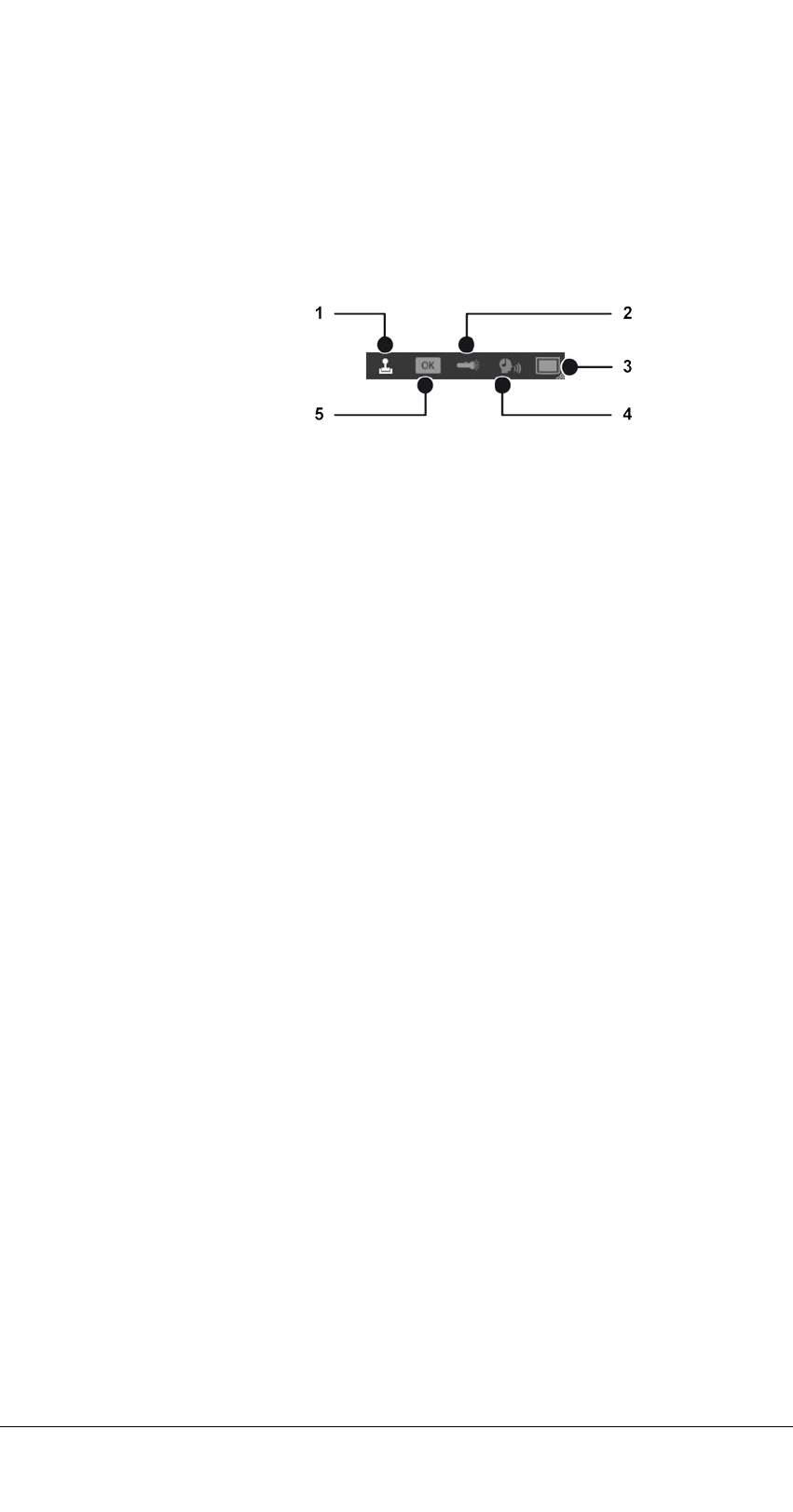
Surveillance mode
4.9 Control
1. To search for a specific item, enter the name of the item in the Search
text box (see Searching in surveillance mode, p. 91).
4.9 Control
Fig. 4-13: Control
The Control control allows you to control the active cameras displayed in the
work area. The following sub-menus are available:
n
PTZ control, p. 80 (1)
n
Buttons, p. 83 (5)
n
Patrol, p. 84 (2)
n
Audio, p. 85 (4)
n
Dispatcher mode, p. 86 (3)
PTZ control
Selected PTZ cameras are operated with the PTZ control. PTZ-related func-
tions are available for PTZ cameras only. If no PTZ camera is selected or the
PTZ function of the camera is deactivated, only digital zoom and digital pre-
set selection is possible.
80 / 120

Fig. 4-14: PTZ control
Using the PTZ control
1. On the menu bar of the control, click PTZ control to switch to the oper-
ating mode of the cameras.
2. Select the camera image, and use PTZ control (1) to move the camera by
moving the bright spot in the desired direction.
3. Drag the Zoom slider (9) up or down to make the camera zoom in or out
of the image. Optionally, click the four direction arrows at the PTZ con-
trol to move the camera incrementally.
Using preset positions
Including the default position, ten preset positions are available by direct
selection on the number field (8). More can be available in the drop down
menu. The maximum number of presets depends on the camera. To edit pre-
set positions in surveillance mode see Editing camera preset positions, p. 83.
Surveillance mode
4.9 Control
81 / 120

Surveillance mode
4.9 Control
In general positions are set in the configuration mode by an administrator in
the Camera area.
1. Click the required camera position on the number field (8) to pan the
camera to the selected position.
2. Optionally, click the triangle beside the position name, and select the
desired position from the drop-down list. The position is immediately
approached.
Using multiple preset positions of a single camera in a single layer
Instead of using a fish-eye camera for a 360° view, multiple fixed camera
images can be combined in a single layer (for layers in surveillance mode, see
Custom layers, p. 70).
Saving a layer remembers the camera position (digital preset, digital zoom,
dewarping position) and when opening again will resume at the same pos-
ition.
This applies to saved layers in configuration mode as well as for local layers.
Layers that are inserted into a video wall by drag & drop will retain the digital
camera position on the video wall.
Exposure and focus setting
The following exposure and focus settings are available only if supported by
the camera.
Iris settings (2)
n
Iris +, Iris -: Opens or closes the iris of the camera to control the bright-
ness.
n
Auto Iris: Automatically adjusts the iris opening to the optimum bright-
ness of the environment.
n
Autofocus: automatically adjusts the image sharpness to the objects in the
camera focus.
Day- and night mode settings (3)
n
Day mode, night mode: The camera sets a filter when light conditions are
poor.
n
Auto: The camera switches between daytime and nighttime vision auto-
matically.
Focus settings (4)
n
Close-up focus, Close-up focus: adjusts the image sharpness to the
objects in the camera focus, depending on the distance of the object to
the camera sensor chip.
n
Autofocus: automatically adjusts the image sharpness to the objects in the
camera focus.
82 / 120

Editing camera preset positions
Camera (preset) positions can be defined (4), deleted (5) and edited (6)
depending on user rights.
Creating a preset camera position
1. With the PTZ control (1) move the camera to the required position.
2. Click Add new camera position (7). The new camera position is added at
the next free position number.
3. Enter a name for the position and click OK. The new camera position is
added at the next free position number.
Deleting a preset camera position
1. Select the position from the number field or from the drop down menu.
2. Click Delete (6). The deleted camera position is released, and subsequent
positions are shifted to compensate.
Example
1
Editing a preset camera position
1. Select the position from the number field or from the drop down menu.
2. Click Edit current preset (5).
3. Edit the positions by means of changing the position name, PTZ-settings,
focus settings etc.
4. Click Save current changes.
Buttons
Actions or defined processes such as camera recordings or alarm scenarios
are started with buttons.
Fig. 4-15: Buttons
1. On the menu bar of the Control control, click OK to switch to the display
of the buttons created.
1
Position 3 is deleted. Position 4 is then shifted to position 3, position 5 to position 4 and so
on.
Surveillance mode
4.9 Control
83 / 120

Surveillance mode
4.9 Control
2. The buttons that the user is authorized to use are displayed.
3. Activate the desired action by clicking the button.
Patrol
Patrols can display cameras, set positions, maps and layers one after the
other for a specific period. It is also possible to open or close digital outputs
in a patrol and confirm checkpoints.
Fig. 4-16: Patrol
1. On the menu bar of the control, click Patrol to switch to the overview (2)
of the patrols configured.
Starting a patrol
1. Select the desired patrol (1), and click Play (3). The defined cameras, pre-
set positions, maps and layers are displayed one after the other for the
specified period.
Stopping a patrol
1. Click Stop (5) to cancel the selected patrol.
Pausing a patrol
1. Click Pause (4) to interrupt the patrol. The patrol is paused.
84 / 120

Repeating a patrol
1. Click Loop (6). The patrol is repeated.
2. Click Loop (6) again. The repetition is canceled, and no more patrols are
carried out once the current patrol is finished.
Navigating between points in the patrol
1. Click Back (7) or Next (8) to go to the previous or next item in the list.
Audio
1. On the menu bar of the Control control, click Audio to switch to audio
mode.
For audio, two options are available (if supported by the hardware):
n
VoIP
n
Camera
VoIP
Fig. 4-17: VoIP
1. Select VoIP to select voice output over the network (Voice over IP).
2. Move the sliders for the microphone (1) and loudspeakers (2) to adjust
the volume. The volume setting is saved locally for each client.
3. To speak to a person from the address book of the existing users, enter
the name of the person in the text box, and click the magnifying glass
icon or select a person from the list.
4. Click green phone (5) to start the call.
5. Click red phone (4) to finish the call. The name of the person you are talk-
ing to, the person's location and the duration of the call are displayed (2).
6. Click DTMF (3) to send a DTMF-sequence or call a button action. The
sequence or button action is set by an administrator in the VOIP con-
figuration.
Surveillance mode
4.9 Control
85 / 120

Surveillance mode
4.9 Control
Camera
If supported by the camera, audio transmission from the client to the camera
is possible.
Fig. 4-18: Camera
1. Select Camera to select the direct audio system of the camera (if avail-
able).
2. Move the slider for the loudspeaker (1) to adjust the volume. The volume
setting is saved locally for each camera.
3. To start audio communication to the camera press and hold the talk-but-
ton (2).
4. To stop audio communication to the camera release the talk-button (2).
Dispatcher mode
Dispatcher mode is displayed only if the video wall dispatcher is activated
in the View menu (see Video wall dispatcher, p. 36). In addition, at least
one video wall must have been created in configuration mode.
86 / 120

Fig. 4-19: Dispatcher mode
1. On the menu bar of the control, click Dispatcher mode to switch to video
wall control.
2. Select the set video wall (3). The video wall is displayed , including the
monitors (1) it contains.
3. Click Digital zoom (2) and scroll with the mouse wheel to zoom in or out.
4. Press the mouse button and drag the display icons left or right to see
adjacent displays.
5. Drag the desired video sources, layers and maps to the monitor in the
thumbnail (1).
6. If necessary, open the display of the monitor by-clicking it. The monitor
with the active layers is displayed in the work area. You can drag the
video sources, layers and maps directly into the work area if the video
wall monitor is displayed.
4.10 Alarm list and system messages
Fig. 4-20: Alarm list and system messages
Surveillance mode
4.10 Alarm list and system messages
87 / 120

Surveillance mode
4.10 Alarm list and system messages
The alarm list is at the bottom of the screen and can be opened or closed as
required. It displays the combined list of alarm and system messages in the
order of their occurrence. The most recent alarms are displayed first. In addi-
tion, the number of alarms that have occurred is shown in the surveillance
mode icon on the mode bar.
1. To sort the alarm or system messages by the column category, click the
column headings.
2. To change the status of an alarm, select the object in the column Status
and select the status from the drop-down menu.
3.
To collapse or expand the alarm list, click Expand/collapse all .
Alarm messages
All open alarms that have been assigned to the current logged-in profile are
displayed in the alarm messages. The type of alarm can be recognized by the
color-code. The color in which the alarm is displayed can be set in con-
figuration mode in the alarms control.
Changing the alarm status
An alarm has the following statuses:
n
Activated: This alarm is currently active.
n
Confirmed: These alarms have been viewed and will be removed from the
alarm list. These alarms are removed from the alarm list for all users.
n
Deferred: These alarms have been viewed and declared as important by
the applicable user (e.g. security guard), because they will be required at a
later time (e.g. for the patrol report). These alarms are retained in the
alarm list. Deferred alarms are declared open at the next start.
n
Rejected: These alarms are removed from the alarm list and considered
unimportant or not applicable by the user.
1. Click the entry in the Status column of the alarm list to change the status
of the alarm messages.
2. Optionally, click Confirm all to acknowledge the alarms and remove the
red circle displaying the number of unconfirmed alarms.
Classifying an alarm
Every alarm on the alarm list can be classified according to the categories
defined.
1. Select the alarm in the alarm list.
2. Select the category from the drop-down list in the column Classification.
88 / 120

Message window (pop-up)
Fig. 4-21: Message window (pop-up)
As soon as an alarm occurs, a message window is displayed for high or
medium priority alarms.
Low priority alarms are removed from the alarm list at the end of the alarm if
they are acknowledged and another alarm occurs. Low priority alarms do not
have an alarm status.
You can add a comment for this alarm. The comment is displayed in report
mode and archive mode.
1. Click Confirm to acknowledge the alarm. The alarm is deleted from the
alarm list and the next alarm is displayed.
2. Reject the alarm. The alarm is deleted from the alarm list and the next
alarm is displayed.
3. Reset the alarm. The alarm is marked as deferred in the alarm list. No fur-
ther alarm is displayed until an alarm is either called from the alarm list
or acknowledged. This allows multiple alarms to be acknowledged sim-
ultaneously.
Alarm notification
A new alarm is displayed in a highlighted pop-up window that opens from the
bottom of the screen (alarm notification).
Surveillance mode
4.10 Alarm list and system messages
89 / 120

Surveillance mode
4.10 Alarm list and system messages
Fig. 4-22: Alarm notification
The notification window displays the alarm name, its status and the time of
occurrence.
1. Click Switch off notifications to prevent the alarm notifications appear
on the screen.
2. Select the time interval for the alarm message to be hidden ("snooze").
After the selected interval has elapsed, the alarm notification will be dis-
played again.
3. Select the alarm and click Edit to display the message window for editing.
4. Click Close to close the message window.
System messages
The system messages show the errors that have been reported by the sys-
tem, such as failure of a server, database or camera and also losses of con-
nection.
The errors are displayed in descending order by time of occurrence with a
description, the internal error number, the message and the cause of the
error.
1. Select one or more system messages and click Remove selected to
remove the message from the list. The number in the red circle displaying
the number of unconfirmed messages is reduced.
2. Optionally, click Remove all to remove all system messages from the list
and to remove the red circle displaying the number of unconfirmed sys-
tem messages.
90 / 120

4.11 Searching in surveillance mode
The search below the overview tab in the control bar helps you to find the
contents of the active control bar more quickly.
Fig. 4-23: Searching in surveillance mode
1. Enter the search term into the search field (1). The first term found in the
overview is highlighted.
2. Click the magnifying glass on the right of the search field or click [Enter]
on the keyboard to highlight the next term in the overview.
Surveillance mode
4.11 Searching in surveillance mode
91 / 120

93 / 120
Archive mode
Archive mode is used for the retrospective evaluation of recordings. Only
recorded data can be displayed in archive mode. To select the relevant image
data, a camera must be selected in the camera overview or in the Alarm list
and system messages, p. 87.
The recording periods for the selected camera (green frame) are displayed in
a time line in the Archive player, p. 94. The icons for digital zoom and volume
control are also displayed (only for cameras with audio recording activated).
1. To switch to archive mode, click Archive mode in The mode bar, p. 62.
2. Select the camera or layer whose archived image data is to be displayed,
or select an alarm from the alarm list.
Camera overview
The camera overview displays all installed cameras, maps and layers you are
permitted to access. Cameras having integrated exported image data are dis-
played as "<camera name> [archive]".
1. Click the corresponding camera. The camera images are displayed in the
main window.
5

Archive mode
5.1 Archive player
5.1 Archive player
Fig. 5-1: Archive player
The archive player allows control of the playback from a selected camera. The
player is divided into two sections. The actual archive player is shown on the
left and timeline on the right.
The archive player has the following functions:
n
Bandwidth optimization options (1): Depending on the license and con-
figuration an optimized video stream can be selected to reduce client and
network load.
n
Previous frame (2): Jumps to the recordings previous video frame.
n
Play backward (3): Plays the archived video stream in reverse chro-
nological order.
n
Pause (4): Pauses the playback.
n
Play (5): Plays the recorded video in the correct chronological order.
n
Next frame (6): Jumps to the recordings next video frame.
n
Real time (7): Plays the event in real time.
n
Next alarm recording (8): Jumps to the selected camera's next alarm
recording.
n
Skip pause (9): Skips the pause between two recordings in playback mode.
n
Calendar (10): Opens a calendar window in order to navigate to a specific
calendar time (date and time).
n
Zoom out from timeline (11) or Zoom in to timeline (12): Enlarges or
reduces the size of the display of the timeline. You can also zoom within
the recording period by clicking the timeline and then turning the scroll
wheel on the mouse.
n
Update timeline (13): Updates the camera's timeline. For manual syn-
chronization with edge storage recordings, hold down the CTRL key when
clicking the icon.
n
Add bookmark (14): Adds a bookmark to the current frame (see Adding a
bookmark, p. 103).
n
Bookmark overview (15): Displays the overview of all bookmarks(see
Working with bookmarks, p. 102).
n
Set marker (16): Sets the start and end markers for a selected area of the
timeline (see Editing an area, p. 95).
n
Synchronized mode (17): All visible cameras are synchronized to the time
of the selected camera by default. If the synchronized mode is deac-
tivated, each camera can show a different point in time.
n
Write protection (18): Sets write protection for the marked area of the
timeline. See Write protection, p. 99
n
Delete area (19): Deletes the marked area from the timeline.
94 / 120

n
Export area (20): Starts the AVI export or the Qognify video data export
(see Exporting recordings, p. 97)
n
Jog dial (21): Plays the sequence forward and backward. The further you
turn the jog dial to the right or left, the faster the sequence is played for-
ward or backward. The playback speed is displayed in the number field
(22).
n
Timeline / time stream (23): See Timeline / time stream, p. 95.
Using the jog dial
1. Turn the jog dial with the mouse to the left or right to play the sequence
backwards and forward. When releasing the jog dial, it will return to the
center position.
2. Click on a dot around the jog dial to position it there.
3. Click on the double bar above the dial to release.
Timeline / time stream
The time displayed in the timeline may differ from the time displayed in
the video due to the way Cayuga stores the timestamp information (refer
to Time zone handling).
The timeline / time stream allows you to search across the entire recording
period for relevant image material. The important color markings are:
n
Green (standard recording)
n
Red (alarm recording) - or any other color than green
1. Zoom into the recording period by clicking the timeline and turning the
scroll wheel on the mouse. This improves the overview of the recording
start of the camera.
Editing an area
1. Click the camera next to the jog dial. If one camera is played or multiple
cameras are played synchronously, the current time of the archive is dis-
played next to the playhead. If multiple cameras are played asyn-
chronously, the current time of the archive is not displayed.
2. On the timeline, click Set markers (16) to mark the beginning of the sec-
tion to be edited.
3. Move the time bar to the of the end of the section to be protected.
4. Click Set markers again to specify the area.
5. Click Delete area to remove the area from the timeline.
6. Click Export area to export the area.
Archive mode
5.1 Archive player
95 / 120

Archive mode
5.1 Archive player
7. Select the required data format (Type), and click OK. The following
export formats are available:
—
Qognify data format: The exported data are password-protected and
can only be viewed with the viewer.
—
AVI: The exported data are not password-protected and can be
viewed with any film software. This represents a high data pro-
tection risk.
8. Specify the required export settings (see Multiple export of image data,
p. 49).
Click-2-Track
The feature is used in archive mode to navigate from one camera to the next
by clicking on the Click-2-Track regions in the image.
The preview of the Click-2-Track region shows the same point in time as the
current archive timeline. If the archive is in playback mode, the preview inset
plays at the same speed as the main image. The current speed and direction
remains the same even when switching between Click-2-Track regions and
changing the camera.
The feature works with playback forward and backward at different
speeds as well as still images.
The history feature
Click-2-Track stores a history of the camera according to the following cri-
teria:
n
Each camera stores the time when it was opened and the time when it
was replaced by the next camera.
n
When navigating to the next entry in history, the camera shows the open-
ing time.
n
When navigating to the previous entry in history, the camera shows the
closing time.
n
Only the Click-2-Track uses from the current tile are saved in the history
feature. All tiles have their own history.
Example
1. Camera A is viewed from 8:00 to 8:01, then the region for Camera B is
selected.
2. Camera B is viewed from 8:01 to 8:02, then the region for Camera C is
selected.
3. Camera C is viewed from 8:02 to 8:03, then the button Back in the his-
tory is used. The view jumps to Camera B at 8:02 with a still image,
regardless of the previous speed.
4. When the button Back in history is used again, the view will jump to
Camera A at 8:01 with a still image.
5. Using the button Forward in history, the view jumps to Camera B at
8:01, using it again jumps to Camera C at 8:02.
96 / 120

5.2 Exporting recordings
Exporting a single frame
1. In the frame tile, select Advanced export.
2. Select the export format:
—
Save video frame in file. This saves the selected frame as a static
image file (JPG).
—
Print video frame. This prints the selected frame as hardcopy with
additional information such as camera and recording time.
Exporting a video file
1. After selecting a time span in a recording by setting the start marker and
the end marker.
2. Select Advanced export in the timeline.
3. Select the export type Video data export (password encrypted Qognify-
specific format) or AVI export (unencrypted data format).
If video data export is selected, the recordings are exported to the
server or to the client (see Multiple export of image data, p. 49).
If the export process is interrupted, e.g. due to a network error, it will
automatically be resumed as soon as possible.
4. Proceed according to the required targets (for the following procedures,
refer to Multiple export of image data, p. 49).
Exporting the Click-2-Track history with the
Export Designer
When exporting an event with the Export Designer, the Click-2-track history
can be exported as well.
For the cameras with Click-2-Track enabled, this handover feature also
works in the Anywhere Viewer, p. 115.
Archive mode
5.2 Exporting recordings
97 / 120
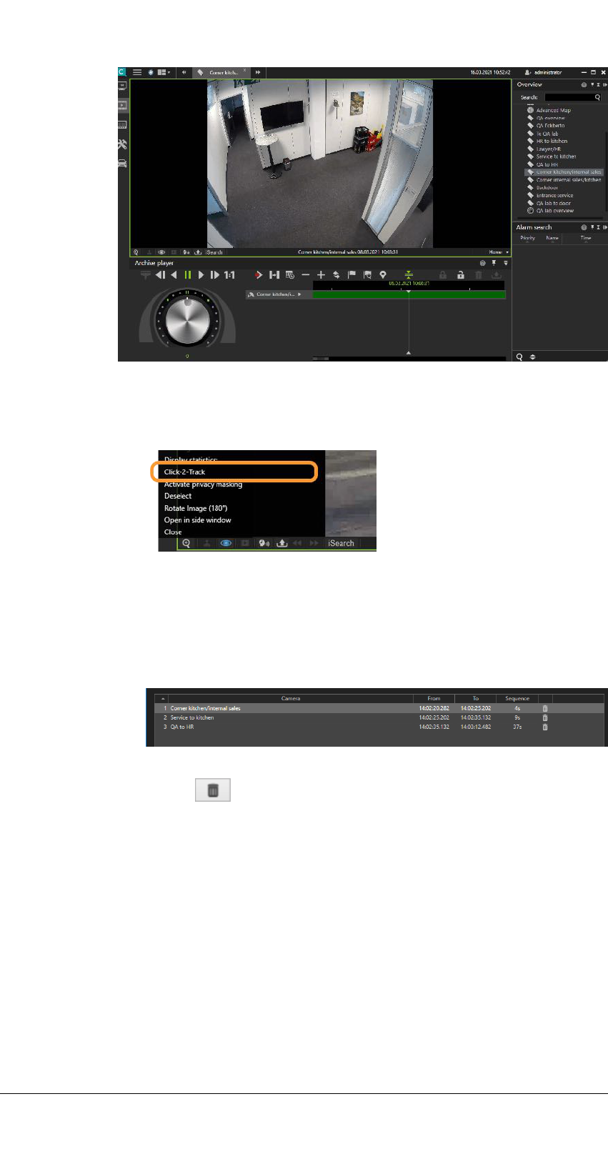
Archive mode
5.2 Exporting recordings
Fig. 5-2: Example of following a person in archive mode with Click2Track
1. Open the camera in the archive player.
2. Select Click-2-Track in the camera options.
3. Select Activate and follow the shapes in the image sequence by clicking
on the respective shape. This opens the camera sequence of the assigned
camera.
4. Select Click-2-Track > Open history in Export Designer to start the
Export Designer (see The Export Designer, p. 45). The Click-2-Track his-
tory of the camera is displayed in a list as sequences.
5. To delete a sequence from the export, select the sequence and click
Delete . By default, all sequences are exported.
Evaluating exported video data
There are two options for evaluating the exported video data:
n
On a system without a Qognify installation, the video data can be eval-
uated using the Qognify Cayuga Viewer (see Anywhere Viewer, p. 115).
n
To integrate the video data within a Qognify installation, an "archive cam-
era" must be created in the configuration mode.
98 / 120

5.3 Write protection
Write protected recordings remain in the zone directory and will not be
deleted. Make sure that sufficient disc space on the zone partition is avail-
able.
Due to legal regulations, write protection may not be used for install-
ations in France.
Set write protection
The protected range in the timeline is at least as wide as the range selected
by the user, as Cayuga may protect a wider range, for example to optimize
the performance of the Multimedia Database (mdb). The actual protected
time range is displayed after setting the write protection.
1. On the timeline, click Set markers to mark the beginning of the section
to be protected.
2. Move the time bar to the of the end of the section to be protected.
3. Click Set markers again to specify the section.
4. Click on the closed padlock to protect recordings from being overwritten
or deleted.
Remove write protection
1. Click open padlock in the Archive player.
Archive mode
5.3 Write protection
99 / 120

Archive mode
5.4 Searching for alarms
Fig. 5-3: Remove write protection
2. In the displayed window click Start query.
3. Select the write protected sequences. Hold the CONTROL-key to select
multiple sequences.
4. Click Remove write protection.
5.4 Searching for alarms
The time displayed in the timeline may differ from the time displayed in
the video due to the way Cayuga stores the timestamp information (refer
to Time zone handling).
100 / 120
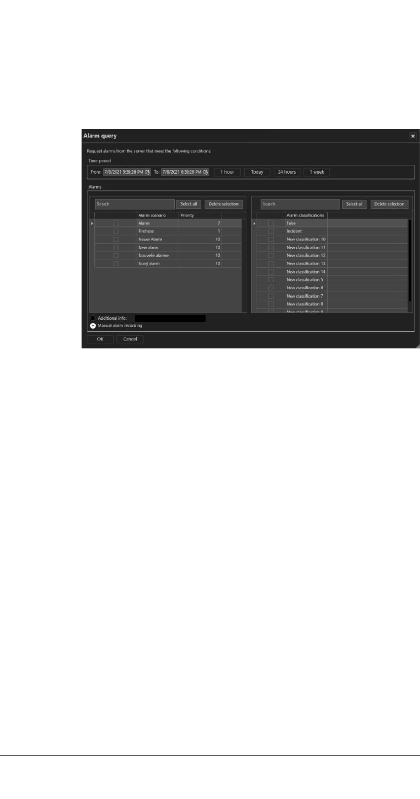
With the alarm search you can search for specific alarm depending on con-
figurable conditions.
Creating an alarm query
Fig. 5-4: Searching for alarms
1. Click New request in the Alarm search control. The Alarm query is dis-
played.
2. Specify the Time period for the alarm to be searched.
3. Optionally, select the recent time intervals of the last hour, the last 24
hours, the last week, or the current day.
4. Select the “Alarm scenario”, either by name or by priority.
—
To select all items, click Select all.
—
To deselect, click Delete selection.
5. Select the “Alarm classification” either by direct selection or by searching
the classification term.
6. If available, enter the additional information that is obtained by network
triggers (e.g. Network IO or SiPass) to be searched for.
7. Select Manual alarm recording to include manual recordings of the avail-
able video sources in the search.
8. Select the recordings of the camera or cameras to be searched.
9. Click OK to start the search.
Alarm search results
The results of your alarm query are displayed in the Alarm search control.
Archive mode
5.4 Searching for alarms
101 / 120

Archive mode
5.5 Working with bookmarks
Fig. 5-5: Alarm search results
1. Click on one of the column headings Priority, Name or Time to sort the
results accordingly.
2. Click on the on the arrow on the left of an alarm to display details.
5.5 Working with bookmarks
Bookmarks can be set in archive mode or when starting or ending a manual
alarm recording (see Manual alarm recording, p. 74).
102 / 120

Adding a bookmark
1. Move the timeline to the position where you want to set the bookmark.
2. Click Add bookmark (15) in the Archive player.
Fig. 5-6: Adding a bookmark - 2
3. Enter a Name for the bookmark.
4. Select the Camera for which you want to bookmark the recording from
the drop-down menu. The drop-down menu contains all cameras in that
are currently displayed in the archive player. By default, the currently act-
ive camera in the archive player is selected.
5. Enter a description, if required.
6. Click Add bookmark. A flag will be added to the time line of the selected
camera.
Archive mode
5.5 Working with bookmarks
103 / 120

Archive mode
5.5 Working with bookmarks
Bookmark overview
In the bookmark overview, bookmarks can be displayed, edited and deleted.
1. Click Bookmark overview in the Archive Player.
2. Select one or more cameras or click Select all to select all cameras dis-
played (i.e. cameras with bookmarks attached).
3. Optionally, search for the camera name or the bookmark.
4. Search bookmarks for all cameras even if only visible in the archive. Book-
marks from cameras of different installations can be searched sim-
ultaneously.
5. To deselect, click Cancel selection.
6. Activate Search within a range to narrow the time window for the
search and specify the time interval.
7. Click Start search to display only the bookmarks within the specified
time interval. The bookmarks are displayed in the "Bookmarks" section.
8. Select a bookmark from the "Bookmarks" section. The information asso-
ciated with the bookmark (time, the assigned camera and the description)
is displayed in the right area.
9. Double-click on the bookmark to navigate to the corresponding time
marker.
10. To edit the information, select Edit (1) (see Adding a bookmark, p. 103).
11. To delete the bookmark, select Delete (2).
Bookmarks are not deleted with the video data, because they are stored
in a separate event database. They are deleted automatically, once the
oldest video image is newer than the time stamp of the bookmark.
104 / 120

5.6 Edge storage import
Edge storage uses the camera to store images on an internal storage media
(e.g. SD card) to cover connection failures between the camera and the data-
base server. If the connection between the camera and the server is inter-
rupted, recording gaps on the DeviceManager will result.
After the connection is reestablished, the recording gaps on the server can be
filled with the recordings from the camera's internal storage media. Time
schedules for recording and maximal recording size are taken into con-
sideration..
Depending on the configuration of the camera, edge storage data can be
imported automatically or manually.
Manual edge storage import
1. For manual edge storage import, hold down the CTRL key when clicking
Update timeline (13).
5.7 iSearch
iSearch in archive mode searches recordings for motion in specific image
regions. The searchable time period is 5 to 60 minutes.
The performance of iSearch depends on the performance capability of the
client hardware, since the search is carried out exclusively on the client.
Archive mode
5.6 Edge storage import
105 / 120

Archive mode
5.7 iSearch
Configuring iSearch
1. Select the related camera.
2. Click iSearch at the bottom of the video image and select a time range
between 5 and 60 minutes. The maximum selectable time range depends
on the access restrictions of the user for the archive.
A dotted rectangular icon is displayed on the right side of the iSearch
button.
3. Click on the area icon and select the shape of the search area. The fol-
lowing shape options are available:
—
Rectangle
—
Circle / ellipse
—
Polygon
—
Delete shape
—
Delete all shapes
4. In the camera image drag the selected shape to the desired position. A
semi-transparent area is laid over the image in the selected position.
If you selected the polygon for this purpose, click a point in the image
for each corner and close the polygon by double-clicking the last
point.
Fig. 5-7: Configuring iSearch
106 / 120

5. Within the selected area, select either Any kind of motion (default) or A
single event.
—
Any kind of motion: This search method searches for all changes
within the image in the specified period. The search can be per-
formed for the whole image or for parts of the image as specified by
the user. The search may take some time depending on the selection.
—
A single event: This search method is particularly quick. It is possible
to search through several days of image material in a few seconds.
However, this method only works if a single, lasting event has
occurred in the camera's selected field.
6. Optionally select Expert mode to fine tune the search.
iSearch in expert mode
Fig. 5-8: iSearch in expert mode
In Export mode the following fine adjustments are available:
n
Dead time in seconds specifies how much time has to elapse after motion
detection in the image or part of the image before another hit is displayed
in the result list.
n
Pixel threshold detects changes in the image when the camera is oper-
ating in extreme light conditions. A change in the image is interpreted as
motion if it exceeds the threshold. The higher the threshold, the greater
the change in the image has to be before it is considered to be motion.
n
Maximum number of frames per second if not all of the recorded frames
have to be searched. This can speed up the search significantly.
n
Maximum pixel limit for interval search: The maximum pixel limit for an
interval search only has an impact on searches for a lasting change. The
specified start and end points of the period in which the search is to be
carried out are compared continuously. If the two points currently diverge
by more than the specified pixel limit, interval bisection is interrupted, and
a serial search with greater increments is started until the pixel limit is
adhered to again. The interval search is then resumed from this point. This
setting improves the search under extreme lighting conditions (strong con-
trast between light and dark areas or objects passing).
n
Show help dialog after single search, if appropriate. On completion of the
search, you can specify in a dialog whether or not the event has been
found and whether you want to switch to archive mode with the event
found.
1. Specify the desired settings and start the search.
2. To exit expert mode, click Normal mode.
Archive mode
5.7 iSearch
107 / 120

Archive mode
5.7 iSearch
Deleting a search area
1. Click the search area, and select Delete to delete only the selected area.
2. Optionally, select Delete all to delete all areas.
108 / 120

109 / 120
Report mode
Report mode gives you an overview of the events that have occurred in the
form of a list. Distinctions are drawn between:
n
User events (display of events that concern specific users)
n
Alarm events (events that have occurred)
n
Camera usage (display of events that a specific camera)
n
System messages (display of events that concern specific services)
In addition, the camera usage of users can be tracked.
The maximum number of events to be displayed can be specified in the cli-
ent configuration (see Client configuration, p. 17).
1. To switch to report mode, click the Report mode icon on the mode bar.
2. Click a column header in the main window to sort the events in ascend-
ing or ascending order based on the column's category (date/time, user,
description).
6.1 Filtering the query
In report mode, the following event types can be evaluated:
6

Report mode
6.2 Exporting the analysis as spreadsheet file
n
Alarms can be filtered for alarm scenarios
n
Users can be filtered for:
—
Camera configuration
—
Archive
—
Export
—
Patrols
—
Actions
—
Log on or log off
—
Change mode
n
Camera usage can be filtered for:
—
Camera (only if the DeviceManager records camera usage)
—
Users
n
System can be filtered for:
—
Core services
—
Image storage
Depending on the area, the query results can be filtered.
1. To filter the events on the basis of specified criteria, select the type of
event you are searching for on the Query for control bar.
2. Select the user or users related to the events to be searched for.
3. Select the desired events. The items are displayed in the list below.
4. Select specific items by clicking the check box in front of the item's name
or click select all.
5. To deselect, click Delete selection.
6. To further narrow the selection, specify dates and times to define the
time period.
7. Start the query. Only the events that meet the selected criteria are dis-
played in the main window.
6.2 Exporting the analysis as spreadsheet
file
You can also export the result as a comma-separated file (*.csv).
1. Export the result in order to analyze it in a spreadsheet program.
110 / 120

6.3 Saving a query as report template
Additionally, the search criteria can be saved for future queries.
1. Click Save.
Fig. 6-1: Saving a query as report template
2. Enter the Report template name.
3. Optionally, select Save timestamp relative to current time. This option
will use the time interval of the current query for the next query.
Example
1
4. Click OK to save the query.
5. To use a previously saved query, select the name of the query in the
drop-down menu and click Start query.
6. To delete the saved query, select the query from the drop-down menu
and click Delete.
1
The current query searches for events within the last 24 hours. When the query is saved with
a relative time stamp, the next query will also search within the last 24 hours - relative to the
next query.
Report mode
6.3 Saving a query as report template
111 / 120

113 / 120
Shortcut keys
The following keyboard shortcuts are available for users in the client to speed
up function calls.
More shortcuts are available and configurable in the client configuration
(see Keyboard shortcuts, p. 28).
Shortcut key Meaning
CTRL+1 Switch to surveillance mode
CTRL+2 Switch to archive mode
CTRL+3 Switch to report mode
CTRL+4 Switch to configuration mode (only possible as administrator)
CTRL+5 Switch to LPR mode
CTRL-Y Display statistics in video image in Surveillance and Archive mode
F10 Switch full-image mode on or off
F1 Show Qognify User's Guide
F2 Moves all windows to primary display (only when multiple displays
are connected)
ESC Hide all controls
+/- When digital zoom is active, pressing + or - zooms in or out
7

115 / 120
Anywhere Viewer
The Anywhere Viewer can be used to access exported image data that are in
the Qognify image format without connection to the database.
The Viewer displays recorded data only in Archive mode. All other modes
are not accessible as they require database access.
n
The Viewer is automatically installed as a subset of the Cayuga client
installation. It can also be installed separately in a user-defined install-
ation.
n
The Viewer is exported to the export folder with any video data export.
n
The Viewer manual is installed in the manual folder during installation.
When viewing files that are exported to the local hard drive of the client
with the Viewer, any local installation of the Cayuga client must be quit
to prevent conflicts.
1. Quit Cayuga if running as a normal client connected to a database.
2. Start the Viewer from within the export folder.
8

Anywhere Viewer
8.1 Switching the interface language
8.1 Switching the interface language
Without a Cayuga client installed on the local hard drive, the language
can only be changed using command line parameters.
1. Exit the Qognify Viewer and start the Cayuga client.
2. Change the interface language in the File menu of the function bar in the
Cayuga client (see Changing the language, p. 29).
3. Exit the Cayuga client and start either the Cayuga client in Viewer mode
or the Qognify Viewer.
8.2 Import and play recording
Import recording into the Viewer
1. Start the Qognify Viewer (see Login, p. 9). The overview panel with the
available recordings is displayed.
2. To add additional exported camera sequences, select Add exported cam-
eras in the overview panel.
3. Optionally, navigate to the export folder of the recording and start the
Qognify Viewer in the folder.
4. Navigate to the folder where the files are located.
5. Click OK to import the selected data into the viewer.
When opening a folder that contains multiple exported camera
sequences (even in subfolders), all files will be imported.
Fig. 8-1: File selection for importing into the Viewer in offline mode
6. Enter the password specified during export.
7. Apply the password and click OK. Any exported video sequence that
matches the password moves to the "Verified" section on the right. You
can enter and apply further passwords for additional video sequences.
116 / 120

Importing data into the Qognify Viewer may take some time.
8. Click the exported camera that you wish to view. Alternatively, you can
drag the desired camera to the previously occupied tile. If you imported
multiple sequences from the same camera they will be shown as one cam-
era in the tree. If you open this camera all the sequences of this camera
can be found in the same timeline.
Play recording
Fig. 8-2: The Qognify Viewer controls
The Viewer allows limited control of the playback from one or multiple expor-
ted recordings in a single timeline. In Viewer Mode or in the Viewer you can
use layers to simultaneously display multiple cameras in a grid. Multiple
timelines are displayed just as in the regular Cayuga client.
The Viewer has the following functions:
n
Previous frame (1): Jumps to the recordings previous video frame.
n
Play backward (2): Plays the archived video stream in reverse chro-
nological order.
n
Pause (3): Pauses the playback.
n
Play (4): Plays the recorded video in the correct chronological order.
n
Next frame (5): Jumps to the recordings next video frame.
n
Real time (6): Plays the event in real time.
n
Next alarm recording (7): Jumps to the selected camera's next alarm
recording.
n
Skip pause (8): Skips the pause between two recordings in playback mode.
n
Calendar (9): Opens a calendar window in order to navigate to a specific
calendar time (date and time).
n
Zoom out from timeline (10) or Zoom in to timeline (11): Enlarges or
reduces the size of the display of the timeline. You can also zoom within
the recording period by clicking the timeline and then turning the scroll
wheel on the mouse.
n
Set start/end marker (12): Sets start and end markings (e.g. when export-
ing the selection to an AVI files afterwards).
Bookmarks are not supported in Viewer Mode / Qognify Viewer.
n
Synchronized mode (13): All visible cameras are synchronized to the time
of the selected camera by default. If the synchronized mode is deac-
tivated, each camera can show a different point in time.
Anywhere Viewer
8.2 Import and play recording
117 / 120

Anywhere Viewer
8.3 Export a recording
n
Export area (14): Starts the AVI export.
Exporting in Qognify file format is not supported.
n
Timeline / time stream (15): See Timeline / time stream, p. 95.
n
Jog dial (17): Plays the sequence forward and backward. The further you
turn the jog dial to the right or left, the faster the sequence is played for-
ward or backward. The playback speed is displayed in the number field
(16).
8.3 Export a recording
For information on exporting the recordings, refer to The Export Designer, p.
45.
8.4 Save sequence as AVI file
1. Right-click the camera image and select Save images as AVI files.
2. Select the start and stop time, the export format and the name of the file.
3. The export settings can be used to influence the properties of the video
to be created. By default, the best codec available on your system is
used.
4. If you want to use a different codec and/or change the settings of the
selected codec, select the Advanced settings option. You can also select
the audio export option.
5. Click Select to select the name and the export path for the film
sequence.
6. Click Export to start the export.
The size of the AVI file is restricted to 4 GB.
Limitations and known issues
n
Do not export uncompressed images as film. Ten seconds of exported
image material uncompressed is about 350 MB. If possible, do not use
Windows® default codecs. They yield a poor-quality export result.
n
MOBOTIX cameras can only be exported in the MOBOTIX format. The
XviD codec is recommended.
n
If there are different frame rates and resolutions in the time period that is
to be exported (e.g. change from standard to alarm recording), check the
film sequence, because the selected codec may yield a distorted image
from the time of the change in some cases.
118 / 120

8.5 Selecting multiple layers
1. Select the desired multiple layer in the Layer menu. The layers 1x1, 2x2,
3x3 and 4x4 are available for selection.
2. Select the desired time period that you wish to view in the first tile of the
multiple layer.
3. Repeat the above step for the remaining empty tiles. Alternatively, you
can drag the recordings into the tiles by drag & drop.
4. Right-click the current camera and select Delete camera from layer to
select a different recording.
5. Click the new time period that you wish to view. Alternatively, you can
drag the desired time period to the previously occupied tile.
Anywhere Viewer
8.5 Selecting multiple layers
119 / 120
