
Clean Power
Quadrennial Technology Review 2015
Chapter 4: Advancing Clean Electric Power Technologies
Technology Assessments
Advanced Plant Technologies
Biopower
Carbon Dioxide Capture and Storage
Value-Added Options
Carbon Dioxide Capture for Natural Gas
and Industrial Applications
Carbon Dioxide Capture Technologies
Carbon Dioxide Storage Technologies
Crosscutting Technologies in Carbon Dioxide Capture and
Storage
Fast-spectrum Reactors
Geothermal Power
High Temperature Reactors
Hybrid Nuclear-Renewable Energy Systems
Hydropower
Light Water Reactors
Marine and Hydrokinetic Power
Nuclear Fuel Cycles
Solar Power
Stationary Fuel Cells
Supercritical Carbon Dioxide Brayton Cycle
Wind Power
ENERGY
U.S. DEPARTMENT OF
Clean Power

Clean Power
Quadrennial Technology Review 2015
1
Quadrennial Technology Review 2015
Supercritical Carbon Dioxide
Brayton Cycle
Chapter 4: Technology Assessments
Introduction
e vast majority of electric power generation for the grid is accomplished by coupling a thermal power cycle
to a heat source. e nature and conguration of the thermal power cycle is designed so as to give as ecient
power production as is economically attractive. Much of the DOE R&D portfolio is focused on improving the
overall eciency and economics of electric power generation. To that end, there are three primary areas of
focus for R&D to improve electric power generation eciency: (1) increasing the fraction of the energy in the
heat source that can be harvested for use in the thermal power cycle; (2) increasing the intrinsic eciency of
the thermal power cycle; and (3) decreasing the parasitic power requirement for the balance of plant (BOP).
As will be discussed further below, the rst two focus areas cannot be pursued in isolation as they are oen
antagonistic. For example, recuperative heat exchange within the thermal power cycle can oen lead to a higher
cycle eciency but this may be at the expense of decreasing the amount of heat that can be transferred into the
cycle and lowering the overall process eciency.
Most of the thermal power cycles in commercial operation are either air-breathing direct-red open Brayton
cycles (i.e., gas turbines) or indirect-red closed Rankine cycles which use water as a working uid (typical in
pulverized coal and nuclear power plants). Within each group are a myriad of potential congurations that vary
in size and complexity. For any application, the best thermal power cycle will depend on the specic nature of
the application and heat source.
In addition to these conventional thermal power cycles, cycles based on other working uids can be considered.
In particular, the Brayton cycle based on supercritical carbon dioxide (sCO
2
) as the working uid is an
innovative concept for converting thermal energy to electrical energy.
Numerous studies have shown that these sCO
2
power cycles have the potential to attain signicantly higher
cycle eciencies than either a conventional steam Rankine cycle or even the state-of-the-art ultra-supercritical
(USC) steam Rankine cycle.
1,2,3
Higher cycle eciency will automatically lead to lower fuel cost, lower water
usage, and in the case of fossil fuel heat sources, lower greenhouse gas (GHG) emissions. Further, the sCO
2
cycles operate at high pressures throughout the cycle, resulting in a working uid with a high density which
may lead to smaller equipment sizes, smaller plant footprint, and therefore lower capital cost. Achieving the full
benets of the sCO
2
cycle will depend on overcoming a number of engineering and materials science challenges
that impact both the technical feasibility of the cycle as well as its economic viability.
As will be discussed in greater detail below, the main R&D challenges arise from the very factors that lead to
higher cycle eciency. ese include the use of: (1) elevated pressures throughout the cycle; (2) large duty heat
exchangers to minimize the energy lost in cooling the working uid; and (3) CO
2
as the working uid. R&D
will be needed to develop high eciency CO
2
expansion turbines. ese turbines oer the promise of relatively

Clean Power
Quadrennial Technology Review 2015
2
TA 4.R: Supercritical Carbon Dioxide Brayton Cycle
small size because of the low turbine pressure ratio and the high density of the working uid, but this will be
partially oset by the much higher mass ow rates required and the corrosion properties of high pressure CO
2
.
R&D will be required on seals, bearings, and materials, particularly in applications having elevated turbine inlet
temperatures. R&D will also be needed to develop low cost heat exchangers that are able to attain large heat
transfer duties with small temperature dierences between the hot and cold sides of the exchanger and with a
small pressure drop. is will require R&D into compact heat exchanger designs, assessment of materials for
suitability given the temperatures and pressures required, and advances in manufacturing techniques.
Brayton Cycles based on CO
2
as the working fluid
Power cycles using sCO
2
as the working uid take on two primary congurations relevant to power generation:
1) an indirect-red closed Brayton cycle that is applicable to advanced fossil fuel combustion, nuclear, and solar
applications; and 2) a semi-closed, direct-red, oxy-fuel Brayton cycle well-suited to fossil fuel oxy-combustion
applications with CO
2
capture. ese cycles are described in greater detail in the following sections.
Simple Indirect-fired Brayton Cycle
Figure 4.R.1 shows a block ow diagram for the simple indirect-red Brayton cycle. A working uid, which
may be a pure substance or a mixture, circulates between a compressor and an expansion turbine. ermal
energy is added to the working
uid just prior to the expansion
turbine and a cooler is required
to lower the temperature of the
working uid aer expansion
to the desired inlet temperature
to the compressor. In an ideal
cycle, with an ideal gas working
uid and no irreversibility in
the cycle, the cycle eciency
depends only on the cycle
pressure ratio and increases
monotonically with the
pressure ratio.
4
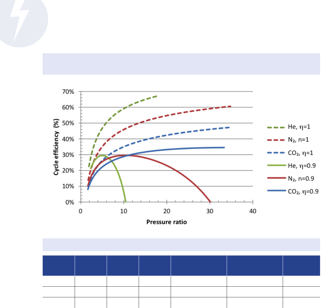
For non-ideal cycles, the cycle
eciency as a function of
pressure ratio passes through
a maximum at some pressure
ratio which depends on the
working uid. Figure 4.R.2
shows the cycle eciency as a
function of pressure ratio for three dierent working uids with an arbitrary turbine inlet temperature of 700°C.
e dashed lines in the gure correspond to ideal cycles in which the turbomachinery isentropic eciency (η)
is 1 and the solid lines correspond to a non-ideal cycle with turbomachinery isentropic eciencies of 0.9. For
each of these cases, heat and pressure losses were neglected so the cycle eciencies are optimistic. Note the
large decrease in eciency and the introduction of an eciency maximum for non-ideal cycles compared to
ideal cycles (see also Table 4.R.1).
Figure 4.R.1 Block Flow Diagram for Simple Brayton Cycle
Credit: NETL
Clean Power
Quadrennial Technology Review 2015
3
TA 4.R: Supercritical Carbon Dioxide Brayton Cycle
Figure 4.R.2 Simple Brayton Cycle Efficiency. Plot of cycle efficiency versus pressure ratio for three different working fluids with ideal turbomachinery
(dashed lines) and non-ideal cycles with turbomachinery isentropic efficiencies (η) of 0.9.
5
Credit: NETL
Table 4.R.1 Non-ideal Simple Brayton Cycle Performance
6
and Working Fluid Properties
7,8
Working
uid
T
c
(K) P
c
(bar) c
p
/c
v
Pressure ratio at
maximum eciency
Turbine exit pressure
at maximum
eciency (bar)
Maximum
eciency (%)
CO
2
304 73.8 1.289 34.9 82.7 34.5
N
2
126 33.9 1.4 10.5 1.0 29.5
He 5 2.3 1.66 5.0 1.0 29.5
Another interesting aspect of the Brayton cycle based on CO
2
is that the cycle eciency is strongly dependent
on the minimum pressure in the cycle. Figure 4.R.3 shows the maximum cycle eciency as a function of
turbine exit pressure for three dierent working uids with an arbitrary turbine inlet temperature of 700 °C
and turbomachinery isentropic eciencies of 0.9. For N
2
and He, the cycle eciency decreases monotonically
as the turbine exit pressure increases. For CO
2
, however, the cycle eciency shows a maximum of 34.5% when
the turbine exit pressure is approximately 82.7 bar (right vertical dashed line in Figure), a bit above the critical
pressure of 73.8 bar (le vertical dashed line in Figure). Note also that for a turbine exit pressure of 1 bar, the
maximum cycle eciency is nearly the same for all three working uids.

Clean Power
Quadrennial Technology Review 2015
4
TA 4.R: Supercritical Carbon Dioxide Brayton Cycle
Figure 4.R.3 Maximum Simple Brayton Cycle Efficiency varies strongly with turbine exit pressure for CO
2
. Plot of cycle efficiency versus turbine exit pressure
ratio for three different working fluids and turbomachinery isentropic efficiencies of 0.9.
9
Credit: NETL
A thermodynamic critical point, as shown in a Phase Diagram (see Figure 4.R.4
10
) is the end point of a phase
equilibrium curve. e end point of the pressure-temperature curve is of interest because this point designates
conditions where a liquid and its vapor can coexist.
11
Table 4.R.1 lists the critical temperature (T
c
) and critical
pressure (P
c
) for CO
2
, N
2
, and Ar. e key property of a uid near its critical point is its higher gas phase
density, closer to the density of a liquid than of a gas. With the CO
2
near the critical pressure at the point of
entrance to the compressor, its
density will be relatively high
and the power requirement
for compression will be lower.
is directly increases cycle
eciency. Another advantage
to maintaining the working
uid above the critical pressure
is that the high uid density
throughout the cycle will
lead to relatively high power
density which is expected
to signicantly decrease the
footprint and capital cost of
the major pieces of equipment,
although this may be oset by
the need to utilize stronger and
more expensive materials.
Figure 4.R.4 CO
2
Phase Diagram
Credit: Wikimedia Commons

Clean Power
Quadrennial Technology Review 2015
5
TA 4.R: Supercritical Carbon Dioxide Brayton Cycle
Recuperated Indirect-fired Brayton Cycle
A more advanced version of
the indirect-red Brayton
cycle incorporates thermal
recuperation. A block ow
diagram for such a cycle is
shown in Figure 4.R.5. e
only change in the cycle is
the introduction of a heat
exchanger between the
expander exhaust and the
compressor exhaust. is
heat exchange improves the
cycle eciency by reducing
the amount of heat lost in the
CO
2
cooler and increasing
the amount of working
uid that can pass through
the cycle for any specied
amount of thermal input.
A byproduct of this eect
is that the pressure ratio for
maximum cycle eciency is
considerably lower than for
simple indirect-red Brayton cycles. Figure 4.R.6 shows the cycle eciency as a function of pressure ratio for
three dierent working uids with a turbine inlet temperature of 700°C (recuperated Brayton cycle—RB). e
dotted curves show the cycle eciency for a simple or non-recuperated Brayton cycle (simple Brayton cycle—
SB). For all working uids, the recuperated Brayton cycle has a higher eciency than the corresponding
simple Brayton cycle over the entire range of feasible pressure ratios. e maximum feasible pressure ratio
for a recuperated Brayton cycle occurs at a much lower pressure ratio than for the simple Brayton cycle. is
maximum pressure ratio occurs
when the compressor outlet
temperature equals the turbine
exit temperature and further
recuperation is no longer
possible. For the recuperated
Brayton cycle, the point of
maximum cycle eciency
occurs at much lower pressure
ratios than for a simple Brayton
cycle. Although the CO
2
cycle
has the lowest maximum cycle
eciency, the eciency curve
is relatively at allowing for
more stable operation. Table
4.R.2 shows the maximum
cycle eciencies.
Figure 4.R.5 Block Flow Diagram for Recuperated Brayton Cycle
Credit: NETL
Figure 4.R.6 Recuperated Brayton Cycle Efficiency. Plot of cycle efficiency versus pressure ratio
for recuperated Brayton cycle (solid lines, RB) with three working fluids compared to the simple
Brayton cycle (dashed lines, SB).
12
Credit: NETL

Clean Power
Quadrennial Technology Review 2015
6
TA 4.R: Supercritical Carbon Dioxide Brayton Cycle
Table 4.R.2 Recuperated Brayton Cycle Performance Compared to Simple Cycle Performance
14
Working uid
Recuperated Brayton Cycle Simple Brayton Cycle
Pressure ratio at
maximum eciency
Maximum eciency (%)
Pressure ratio at
maximum eciency
Maximum eciency (%)
CO
2
4.5 46.8 34.9 34.5
N
2
1.4 52.4 10.5 29.5
He 1.2 52.5 5.0 29.5
It is easy to show that for the recuperated indirect-red Brayton cycle, the cycle eciency increases with
increases in turbine inlet temperature and turbo-machinery eciencies, and decreases with increases in cycle
pressure drop, heat loss, and minimum approach temperature in the recuperator.
13
Recompression Indirect-fired Brayton Cycle
A secondary eect of having the minimum cycle pressure close to the CO
2
critical pressure is that it hampers
the eectiveness of the recuperator somewhat. Near the critical point, the heat capacity of the CO
2
increases
signicantly and the hot CO
2
on the low pressure side of the recuperator does not have as high a thermal
capacitance as the cold CO
2
on the high pressure side of the recuperator. is limits the maximum temperature
that the recuperator can raise the high pressure CO
2
and acts to lower cycle eciency. One approach to mitigate
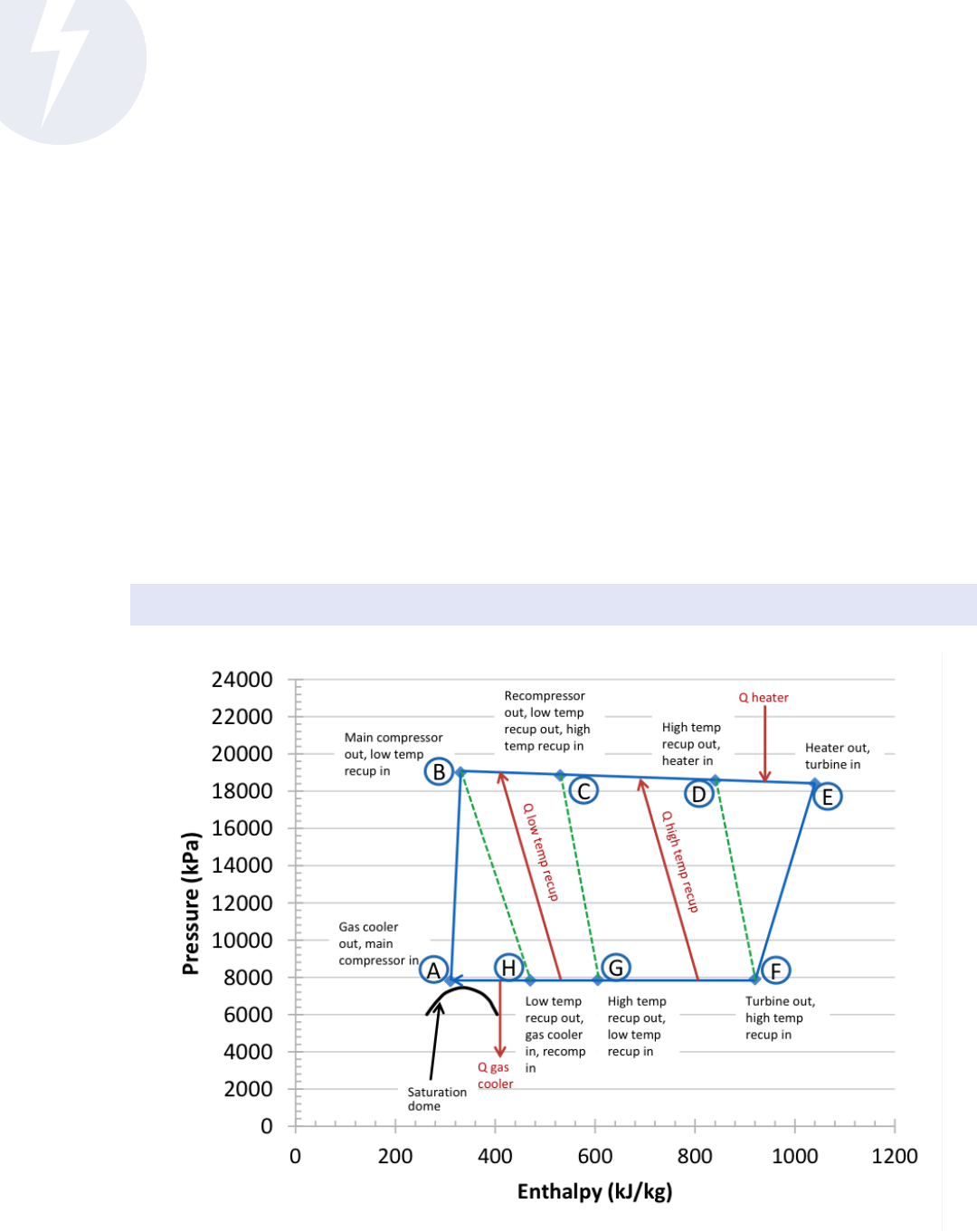
this eect is to use a recompression conguration for the cycle. Figure 4.R.7 shows the block ow diagram for the
recompression indirect-red Brayton cycle and Figure 4.R.8 shows the corresponding pressure-enthalpy diagram.
Figure 4.R.7 Block Flow Diagram for Recompression Closed Brayton Cycle.
15
The state points A through H are defined in Figure 4.R.8.
Credit: Sandia National Laboratories
Clean Power
Quadrennial Technology Review 2015
7
TA 4.R: Supercritical Carbon Dioxide Brayton Cycle
e labeled points A-H in Figure 4.R.8 correspond to state points in the recompression Brayton cycle and are also
depicted on Figure 4.R.7. e operating envelope shown in Figure 4.R.8 corresponds to a recompression sCO
2
Brayton cycle with a turbine inlet temperature of approximately 600°C and a cycle pressure drop of 700 kPa.
Points C-H in Figure 4.R.7 are the same as for the recuperated Brayton cycle. Where the recompression
cycle diers is downstream of point H. In this conguration, a portion of the low pressure CO
2
exiting
the recuperator bypasses the CO
2
cooler and is compressed to the maximum cycle pressure in a separate
compressor from the main CO
2
compressor. In addition to bypassing the CO
2
cooler, this stream bypasses
the low temperature portion of the recuperator. e net thermal eect is to provide a better match of
thermal capacity between the hot and cold sides of the recuperator and increase the overall eectiveness
of the recuperator. e disadvantage of this conguration is that the cycle is more complex and an extra
compressor is required. While the total amount of power required for CO
2
compression actually increases in
this conguration, the net cycle eciency increase because more CO
2
can pass through the cycle for any given
thermal input. Note that in Figure 4.R.7, two dierent values of the temperature and pressure are shown for
state point A. ese correspond to two dierent scenarios for the CO
2
cooler: a wet cooling case using water as
the cooling medium, and a dry cooling case using air cooling. e dry cooling case has a lower eciency than
the wet cooling case but the eciency reduction could be reduced by increasing the minimum cycle pressure.
Figure 4.R.8 Pressure Enthalpy Diagram for Recompression Closed Brayton Cycle.
16
The state points A through H are analogous to those shown in Figure 4.R.7.
Credit: Sandia National Laboratories

Clean Power
Quadrennial Technology Review 2015
8
TA 4.R: Supercritical Carbon Dioxide Brayton Cycle
Figure 4.R.9 compares the cycle eciency of the recompression CO
2
Brayton cycle (RCBC) with the
recuperated Brayton cycle (RB) for CO
2
with a turbine inlet temperature of 700°C. e recuperated cycle
eciency curves for N
2
and He are also shown for comparison. For N
2
and He, the working uid is not near the
critical point at the exit of the cooler and so a recompression cycle oers no benet.
For CO
2
, at the pressure ratio of maximum cycle eciency, the eciency of the recompression cycle is over 5
percentage points higher than the recuperated Brayton cycle. Table 4.R.3 compares the maximum cycle eciency
for the recompression Brayton cycle compared to the recuperated Brayton cycle for the three working uids.
Figure 4.R.9 Recompression Brayton Cycle Efficiency.
17
Plot shows cycle efficiency versus pressure ratio for RCBC (solid line) and Recuperated Brayton Cycle
(dashed lines, RB).
Credit: NETL
Table 4.R.3 Recompression Brayton Cycle Performance Compared to Recuperated Cycle Performance
18
Working uid
Recompression Brayton Cycle Recuperated Brayton Cycle
Pressure ratio at
maximum eciency
Maximum eciency (%)
Pressure ratio at
maximum eciency
Maximum eciency (%)
CO
2
4.4 52.1 4.5 46.8
N
2
1.4 52.4 1.4 52.4
He 1.2 52.5 1.2 52.5

Clean Power
Quadrennial Technology Review 2015
9
TA 4.R: Supercritical Carbon Dioxide Brayton Cycle
Recompression sCO
2
Brayton Cycle versus Rankine Cycle
A direct comparison of the conventional Rankine cycle with the RCBC is dicult because the Rankine cycle
is an established and mature technology and has undergone a century of development and renement. e
state-of-the-art in Rankine cycles today is the ultra-supercritical (USC) cycle having a main steam pressure of
250-290 bar and temperature of 600°C with a reheat temperature of 620°C. Since there are no commercial scale
power plants based on the RCBC, any comparison must be based on assumptions about the operating point.
Although the nature of these two cycles is dierent, they both exhibit an increase in eciency as the turbine
inlet temperature increases. However, the magnitude of that increase will be dierent for the two cycles and
hence each cycle will have a range of turbine inlet temperatures over which its eciency is higher than the
other cycle. ere have been some limited comparisons of the performance of these two power cycles in the
literature
19,20
and they consistently show that the RCBC has a higher cycle eciency at moderate to high values
of the turbine inlet temperature. e exact value of the turbine inlet temperature where the RCBC attains
a higher eciency will vary depending on the selected cycle congurations and assumptions used for the
operating state for the RCBC.
Figure 4.R.10 shows the results of a systems analysis performed at NETL comparing the RCBC with a Rankine
cycle having a single reheat. In this analysis the turbomachinery eciencies for the two cycles were made equal.
e results show the same trend as in prior studies and show that the RCBC has a higher eciency than the
Rankine cycle when the turbine inlet temperature exceeds approximately 425°C.
Semi-closed Direct-fired
Oxy-fuel Brayton Cycle
In addition to the indirect-red
cycles described previously,
direct-red Brayton cycles
using CO
2
as the working uid
are being actively investigated
for fossil energy applications.
Figure 4.R.11 shows a simplied
block ow diagram for this
cycle. e heat source is
replaced with a pressurized
oxy-combustor and hence, the
working uid is no longer high-
purity CO
2
. Since much of the
performance benet of sCO
2
cycles derive from the physical
properties of supercritical CO
2
,
the cycle eciency will decrease as the concentration of CO
2
decreases and hence a relatively pure and near
stoichiometric oxygen stream is advantageous. is will also have the benet of facilitating the capture of the
CO
2
generated during combustion, as part of a carbon capture and storage (CCS) process. e fuel for such a
system may be synthesis gas (syngas) produced by a coal gasier
23
or natural gas.
24,25
As with the indirect-red cycles, the working uid is recycled with thermal recuperation but the combustion
products must be removed from the working uid prior to the recycle. is is expected to be accomplished
through a cooling step to condense and remove water and a purge of a portion of the working uid to remove the
material introduced by combustion, including the CO
2
generated, excess oxygen, and other contaminants from
Figure 4.R.10 Comparison of Recompression Brayton Cycle and Rankine Cycle Efficiencies
21
Credit: NETL

Clean Power
Quadrennial Technology Review 2015
10
TA 4.R: Supercritical Carbon Dioxide Brayton Cycle
Figure 4.R.11 Block Flow Diagram for Semi-closed sCO
2
Brayton Cycle
Credit: NETL
the oxidant or the combustion reactions. Semi-closed direct-red oxy-fuel Brayton cycles oer the possibility
for signicantly higher cycle eciencies than the indirect cycles due to the signicantly higher turbine inlet
temperature that can be achieved in a direct-red cycle. ey are also expected to have a higher power density
than the indirect-red cycles and will be simpler since a recompression bypass compressor is not needed.
Advanced sCO
2
Power Cycles
Both the indirect and direct sCO
2
power cycles are amenable to additional enhancements that can further
increase the cycle eciency. For example, the indirect cycle eciency may increase with the use of reheat
and/or compressor intercooling.
26
Some studies have suggested that lowering the CO
2
cooler pressure below
the critical pressure and condensing the CO
2
into a liquid state will increase cycle eciency since the power
required to pump a liquid is much less than the power required to compress a gas.
27
Cycle congurations have
also been proposed that will increase the range of temperatures over which heat can be harvested in the power
cycle. is may be particularly advantageous with fossil fuel heat sources.
Brayton Cycles based on Other Supercritical Fluids
e supercritical recompression Brayton cycle could utilize working uids other than CO
2
. However, several
factors limit the number of candidate uids for a practical power cycle. To maintain high uid density through
the compression phase, and hence high cycle eciency, the cooler must operate near the critical point of the
uid. Since cycle eciency will increase as the cooler temperature decreases, uids having a critical temperature
that can be attained with coolants readily-available for power plant use (e.g., ambient temperature water)
will have an advantage – in this regard, sCO
2
(critical temperature of 304K, or 87°F) is well-suited. Also, the
critical pressure must be well below the maximum pressure in the cycle and this further limits the number

Clean Power
Quadrennial Technology Review 2015
11
TA 4.R: Supercritical Carbon Dioxide Brayton Cycle
of candidates. When other factors such as safety, thermal stability, corrosion, and cost are factored in, the
number of candidate working uids is quite small. Although extensive analyses have been performed,
29
no
other potential working uids have been identied that are better candidates for the supercritical recompression
Brayton cycle than CO
2
for terrestrial applications.
sCO
2
Brayton Cycles – Summary and Application Areas
A number of Brayton cycle congurations using sCO
2
have been described and their performance
characteristics highlighted. sCO
2
Brayton cycles have a clear potential to attain higher cycle eciencies
than conventional steam Rankine cycles, non-supercritical Brayton cycles, or geothermal power cycles. is
is achieved primarily by selecting the cycle operating conditions to minimize the power requirement for
compressing the working uid and by using a high degree of thermal recuperation.
e range of potential applications for the indirect sCO
2
Brayton cycle is broad since it can be used in
essentially any application that currently uses a Rankine cycle. Generally, the operating conditions where the
recompression sCO
2
Brayton cycle attains its highest eciency requires a large degree of thermal recuperation.
is reduces the heat loss in the CO
2
cooler and allows the heat source to heat the maximum amount of
working uid and hence, generate the maximum amount of power output. A potential disadvantage of this
high degree of recuperation is that the temperature increase of the CO
2
in the heat source is relatively low. If
the hot source operates across a wide temperature range it will create challenges in maintaining high cycle
eciency without discarding a signicant portion of the available hot source energy. Many of the promising
applications for indirect sCO
2
Brayton cycles have heat sources that have a narrow temperature range. Examples
include applications with nuclear, solar, and geothermal heat sources. In each of these cases, the sCO
2
Brayton
cycle operating state can be congured to utilize the maximum amount of energy available from the hot
source. When the hot source temperature range is large, more complex modications to the cycle are generally
required. is may entail a higher degree of process-level heat integration, or reduction in cycle recuperation
to increase the amount of hot source energy that can be utilized in the cycle, or employing a more complex
cascade cycle conguration, or possibly using a combined cycle process in which the sCO
2
Brayton cycle serves
as the topping cycle and a Rankine cycle is used as a bottoming cycle. Conceptual designs have been proposed
for each of these alternatives.
30,31,32
e sCO
2
Brayton cycle can also be congured for direct heating which increases its range of potential
applications. e most promising application areas for direct cycles are with fossil fuel sources. Although it is
overall process eciency and not cycle eciency that will determine whether a given power generation system
is more ecient, for many applications it is straightforward to demonstrate that a higher cycle eciency will
lead to a higher process eciency. is is because the fraction of energy from the heat source that can be
harvested by the power cycle is generally not diminished with the sCO
2
Brayton cycle and there is generally not
an increase in the balance of plant auxiliary power required by the plant for the sCO
2
Brayton cycle compared
to Rankine cycles. Direct cycles also provide an intrinsic method to capture the water generated during
combustion, as liquid water which will partially oset the water withdrawal in a water-cooled application. Oxy-
red direct cycles for fossil fuel applications have the additional benet of facilitating CO
2
capture, signicant
given the EPA’s Carbon Pollution Standards, issued under the authority of Section 111(b) of the Clean Air Act
in August, 2015, that limit CO
2
emissions from new coal-red power plants to 1,400 lb CO
2
/MWh-gross.
33
Table 4.R.4 provides a listing of the major categories of applications for the sCO
2
Brayton cycle, the expected
cycle conguration, the peak temperature for the working uid, and the major benets the sCO
2
Brayton cycle
may potentially demonstrate in each application.
e principal benet of the sCO
2
Brayton cycle is the potential for an increase in both cycle and process
eciency compared to processes that employ Rankine cycles. An increase in process eciency has many
secondary benets including a reduction in the thermal input needed to generate a xed amount of power

Clean Power
Quadrennial Technology Review 2015
12
TA 4.R: Supercritical Carbon Dioxide Brayton Cycle
Table 4.R.4 Potential Applications for sCO
2
for Power Conversion – Modified from Workshop
34
Application Cycle type Motivation
Size
[MWe]
Temperature
(°C)
Pressure
[MPa]
Nuclear Indirect sCO
2
Eciency, Size, Water Reduction 10 - 300 350 - 700 20 - 35
Fossil Fuel (PC, CFB, …) Indirect sCO
2
Eciency, Water Reduction 300 - 600 550 - 900 15 - 35
Concentrating Solar Power Indirect sCO
2
Eciency, Size, Water Reduction 10 - 100 500 - 1000 35
Shipboard Propulsion Indirect sCO
2
Eciency, Size <10 - 10 200 - 300 15 - 25
Shipboard House Power Indirect sCO
2
Eciency, Size <1 - 10 230 - 650 15 - 35
Waste Heat Recovery Indirect sCO
2
Eciency, Size, Simple Cycles 1 - 10 < 230 - 650 15 - 35
Geothermal Indirect sCO
2
Eciency 1 - 50 100 - 300 15
Fossil Fuel (Syngas, nat gas) Direct sCO
2
Eciency, Water Reduction, CO
2
Capture
300 - 600 1100 - 1500 35
which lowers the size and capital cost, and for some applications, also lowers the fuel usage and operating costs.
Increasing process eciency also diminishes the environmental footprint of the process by reducing water
usage and in the case of fossil fuel applications, reducing greenhouse gas emissions.
ere are other potential benets of the sCO
2
Brayton cycle as well although they remain to be demonstrated
as convincingly as the potential for higher process eciency. Because of the relatively high density of the
working uid, there is a potential for some of the unit operations to be smaller and less costly on a $/kWe basis.
However, not all of the properties of the sCO
2
Brayton cycle lend themselves to size and cost reductions. For
example, the sCO
2
Brayton cycle is more complex than the Rankine cycle, requires compressors instead of
feedwater pumps, and requires recuperators having larger heat duties than the heat source.
Another potential benet is that the sCO
2
Brayton cycle may prove to be more practical than the Rankine
cycle for air cooling in locations where water cooling is not available.
35
is is because the working uid cooler
in the sCO
2
Brayton cycle requires signicantly less air ow than an air-cooled condenser in a Rankine cycle
having the same cooling duty. However, this benet is achieved through reduction in the average driving force
for heat transfer in the cooler which would act to increase the required surface area for heat transfer and some
investigators have questioned the practicality of air cooling in the sCO
2
Brayton cycle.
36
With further analysis,
development, and demonstration, the impact of this technology on power plant costs and water usage will
become clearer.
In summary, the supercritical CO
2
based recompression Brayton cycle oers the opportunity to increase
cycle eciency compared to Rankine cycles and some other Brayton cycles and lead to power plants with
higher process eciency. CO
2
appears to be an ideal working uid because it has a critical point well-suited
to terrestrial applications with a moderate critical pressure and a critical temperature that is low enough to be
reached with ambient cooling when the wet cooling option is available. e supercritical CO
2
Brayton cycle may
be applied to direct-heating applications, with potential for high eciency and capture of process water - such
a cycle also facilitates CO
2
capture from the combustion process. When its availability and low cost are factored
in, no other substance is a more attractive working uid for the supercritical Brayton cycle.
While some progress has been made in researching and developing sCO
2
systems, signicant challenges remain
in areas such as material performance, manufacturing, economics, and reliability.

Clean Power
Quadrennial Technology Review 2015
13
TA 4.R: Supercritical Carbon Dioxide Brayton Cycle
Technology Readiness and R&D Needs
Technology readiness is a function of the application (e.g., fossil, nuclear, concentrating solar thermal power,
geothermal), the cycle concept (indirect versus direct cycles), the operating temperature (e.g., high vs low
turbine inlet temperatures) and the plant scale (e.g., small 10 MWe systems vs large utility scale plants). Figures
4.R.7 and 4.R.11 illustrate block ow diagrams for the indirect and direct cycle. e system components
requiring research and development include CO
2
turbines, recuperators, and CO
2
heaters. e technology
readiness is grouped into three categories:
Mature components: cycle components that do not contact sCO
2
Less-mature components
System integration
R&D needs are discussed in the following categories: mature components, less-mature components, system
integration, and specic technology development needs.
Mature Components
In general, components that will not contact the sCO
2
working uid are mature technologies. Design
optimization appropriate for a given application would be required, but none of these components appear to
present an obstacle to commercial deployment, and they can be assumed to be reasonably predictable in their
cost, reliability, and performance. Mature subsystems and components include:
Electrical generation subsystem
Gearbox
Heat rejection subsystem
sCO
2
inventory control
Plant controls
Instrumentation
High power electronics
Less Mature Components
e immature components can be sub-grouped into the indirect cycle needs and the direct cycle needs. e
indirect cycle needs include the CO
2
turbine, the recuperators, and the CO
2
heater. In addition to the CO
2
turbine and recuperators, the direct cycle will require R&D on: (1) advanced pressurized oxy-combustion;
(2) extreme turbine inlet temperatures and associated challenges with turbine materials and blade cooling;
(3) more extensive thermal integration at the cycle and process level; (4) sub-critical CO
2
pumping and
compression; and (5) perhaps additional challenges in fuel processing.
CO
2
turbines
A signicant technology gap is that there are no utility-scale sCO
2
turbines and operational experience at any
scale is limited. e fundamental scientic basis and engineering tools for turbine and compressor design are
fairly mature and reliable. us, there are not expected to be any insurmountable obstacles but it still has to be
designed and tested. Compared to an air breathing turbine, the sCO
2
design must account for dierences in
heat capacity, density, viscosity, and acoustic properties. Particular challenges include materials, seals, corrosion,
erosion, and blade cooling (for turbine inlet temperatures greater than nominal 1400°F [760 °C]). e trade-
o between operating at a high turbine inlet temperature that promises high eciency and the development
challenge is an important system analysis consideration.

Clean Power
Quadrennial Technology Review 2015
14
TA 4.R: Supercritical Carbon Dioxide Brayton Cycle
e high density, high pressure, and rapidly changing material properties of CO
2
near the critical point
represents a relatively new and very dierent regime for turbomachinery design. e small-scale sCO
2
research
turbines and compressors developed to date have performed very close to the design maps generated from
rst principles and have operated eectively above and below the critical temperature without the typical
mechanical slugging that occurs with steam. erefore, it is anticipated that there will not be major surprises
in the turbomachinery design and operating eciency as the technology is scaled up to higher power levels,
but high quality designs and precision machining of both the compressor wheel and turbine wheel are essential
to achieving high component eciency and resulting high system eciency. Selecting the scale for testing
is also important in order to simplify turbomachinery scale-up. Figure 4.R.12 shows the eect of design on
turbomachinery capacity. A nominal 10 MWe capacity is selected as a pilot scale capacity to facilitate eective
scale-up.
Recuperators
Internal heat transfer through recuperation signicantly increases the eciency of a cycle with xed
turbomachinery conditions by reducing the amount of external heating and cooling required by the cycle. e
technical challenge is determining the optimal cycle design, balancing increases in eciency with the increased
system costs as more recuperation is added.
A major constraint to the design is to avoid a large pressure drop along each leg of the heat exchanger, while
pursuing high heat transfer eectiveness. e design must accommodate high operating temperatures and
pressures, and reductions in costs need to be demonstrated. In addition, maturing manufacturing processes will
be needed to address diusion-bonding techniques, investment-casting research, and in-service inspections as
it relates to manufacturing economics.
Figure 4.R.12 Ranges of Application for Key Brayton Cycle Turbomachinery Components and Features
37
Credit: Sandia National Laboratories

Clean Power
Quadrennial Technology Review 2015
15
TA 4.R: Supercritical Carbon Dioxide Brayton Cycle
CO
2
Heaters
More so than for any other component, the design of and associated developmental challenges of the CO
2
heater will depend on the individual application and heat source. Of particular importance to the heat source is
the temperature prole.
For indirect sCO
2
Brayton cycles, the nal stage of heating the CO
2
before it enters the turbine poses a similar
set of challenges as for recuperators. While analogs exist in the existing Rankine cycles, the CO
2
heater poses
additional engineering challenges. e heat capacitance of the CO
2
is much lower than water on a weight
basis. Compounding this problem is the fact that the average driving force for heat transfer (i.e., temperature
dierence between the hot side and cold side) in the CO
2
heater is expected to be much lower than the
comparable driving force in a Rankine cycle boiler. is means that the required heat transfer area will be much
greater. e need for a design that minimizes pressure drop is just as important for the CO
2
heater as for the
recuperators.
With indirect fossil-fueled combustors and bottoming cycle applications, the heat source temperature prole
will be very broad and the sCO
2
cycle conguration will need to allow for the absorption of sensible heat from
the ue gas down to a low level. Otherwise, a high cycle eciency will be wasted due to a low overall recovery.
In the direct-red cycles, the driving forces are expected to be much higher but so too will be the nal
temperature of the heated CO
2
. A perhaps more signicant challenge is designing the oxy-combustor for high
pressure operation with a minimum amount of excess oxygen.
System Integration
For any given application, system integration is an important development eort that will be needed to
optimize the operating and design parameters of the cycle and address start-up, shut-down, transient, and part-
load operation. Dynamic processes within the system, such as pressure surging, heat transfer and convection,
turbulent ow conditions, pressure waves, and acoustics must be considered for the integrated plant operation.
System integration also requires taking into account the eects of unavoidable impurities in the sCO
2
working
uid such as carbon monoxide and water vapor on the critical properties of pure carbon dioxide, such as
forming carbonic acid.
Specific Technology Development Needs
e following provides examples of specic fundamental R&D needs.
Turbomachinery
As noted above, seals and bearings illustrate two specic technology development needs for achieving reliable
and economic turbomachinery.
Seals: Both the turbine and the compressor shas of sCO
2
systems must penetrate high pressure boundaries
yet have minimal friction to their rotation. is has not been demonstrated at the pressures and temperature
needed for sCO
2
applications, nor at the power levels required by industry (10 MWe to 1,000 MWe). A potential
solution is to isolate the sha seals for the generator, radial, and thrust bearings, and any necessary starter
motors from the high pressure/high temperature CO
2
environment. Placing these components outside the high
pressure/high temperature environment would allow use of industry standard bearings whereas keeping them
inside leads to shorter sha lengths and improved rotor dynamics.

Clean Power
Quadrennial Technology Review 2015
16
TA 4.R: Supercritical Carbon Dioxide Brayton Cycle
Commercial experience with sCO
2
sha seals to date is largely based upon CO
2
transport and injection
operations in support of enhanced oil recovery. is application has been successfully met in a range of low
temperature supercritical uid conditions at low to moderate sha speeds (3,600 to 8,000 rpm) by non-
contacting CO
2
-lm dry-gas seals. O-the-shelf solutions for high pressure sCO
2
sealing do not presently meet
the requirements for the high temperatures that would be required at the turbine end of a sCO
2
power cycle.
Bearings: Proper design and selection of bearings is frequently one of the most important factors to
turbomachinery system performance and reliability. e technical challenge is to determine the approach that is
suitable for the conversion system and develop a specic conguration that results in acceptably low frictional
loss and also survives the corrosion and erosion environment. A number of dierent technologies may be
considered, but, for high-speed, high-load applications such as power production turbomachinery, uid lm
(hydrodynamic) bearings and rolling element bearings have historically been the industry workhorses.
Materials
Each application will have specic material design and code requirements. For example, ASME Code Section
III stipulates that only ve materials may be used for construction of nuclear reactor components for high
temperature service. e use of the high-temperature nuclear construction materials will be required for all the
components of the primary and secondary systems of advanced nuclear plants. However, it is not clear where
the boundary of material use for the balance-of-plant will be drawn and where other materials may be used.
Corrosion considerations for the use of the Section III high-temperature nuclear construction materials and
for the use of materials in Sections I and VIII power boilers and unred pressure vessels are not addressed by
the ASME Code, other than by the general requirement stating that such corrosion shall not compromise the
required section thickness or strength of the components.
Materials reliability uncertainties include: carburization and sensitization, high-temperature corrosion,
erosion, creep, and fatigue. e eects of material interactions can impact the design, reliability, and lifetime of
essentially all system components. ese uncertainties and R&D needs are discussed below.
Carburization and Sensitization: Internal carburization and sensitization is a long-term concern for
conventional austenitic stainless steels such as types 321 and 347, but is less of a concern for higher alloyed
materials like alloy 709 and Ni-base alloys where the solubility of C is much lower. Similar carburization of
ferritic-martensitic steels also has been observed at 550°-650°C. If these less expensive ferritic-martensitic and
austenitic steels are to be used, R&D is needed on the long-term carburization behavior and maximum use
temperature of these alloys to identify degradation mechanisms and for prediction of useful life.
High Temperature Corrosion: Based on relatively short-term oxidation tests, the high-temperature oxidation
behavior of candidate advanced ultra-supercritical steam cycle (A-USC) alloys was found to be as good as, or
better, in sCO
2
than in sH
2
O, making them candidate alloys for indirect sCO
2
power cycle components also.
ese leading alloy candidates need to be tested for longer time periods (e.g. 1,000-5,000 hours) at 20-35 MPa
at target temperatures (650-750°C) in sCO
2
to establish oxidation reaction kinetics and quantify the rate of
internal carburization. Furthermore, the long-term eect of various joining techniques (e.g. diusion bonding,
brazing, etc.) on reaction rates needs to be determined. For the direct-red concept, only information at 1 bar is
available on how impurities such as O
2
, H
2
O, and others introduced in the CO
2
stream from the combustion of
fuel may aect corrosion rates. us, oxidation/corrosion data results in supercritical conditions are needed.
Erosion: Erosion is a signicant issue for the closed Brayton Cycle systems at two sCO
2
test facilities: SNL and
Bettis. Substantial erosion in the turbine blade and inlet nozzle has been observed. It is believed that this is
caused by residual debris in the loop and/or small particulates that originate from the spallation of corrosion
products of dierent materials and at dierent locations within the loop. ese particles are entrained through
the nozzle vane and turbine, thus causing erosion. e problem in sCO
2
cycles is exacerbated by the fact that

Clean Power
Quadrennial Technology Review 2015
17
TA 4.R: Supercritical Carbon Dioxide Brayton Cycle
sCO
2
is nearly twice as dense as supercritical steam and moves 11 times faster (in terms of mass ow rate) than
supercritical steam in their respective systems. us, the compact size of the turbomachinery in the sCO
2
cycles
results in a ow of a high density uid at very high velocities. Owing to turbine speeds remaining constant,
the issue of erosion is expected to be encountered in scale-up. In addition, inspection of the printed circuit
heat exchanger within the closed Brayton Cycle system found an agglomeration of hydrocarbons and erosion
products at the inlet.
To address the erosion issues in gas and steam turbines, a wide variety of coating systems have been explored
by industry and various erosion-resistant coatings are in commercial use today. e selection of an appropriate
coating system depends on the underlying substrate metal as well as (perhaps more importantly) on the source
and properties of the particulate causing the erosion. For example, Bettis employs a procedure that lters the
CO
2
ve times before use.
Creep and Fatigue: Creep, the tendency of a solid material to deform slowly and permanently as a result of
mechanical stresses below its yield strength at elevated temperatures, and fatigue, a failure mechanism that
occurs when the component experiences cyclic stresses or strains that produce permanent damage, are primary
potential limitations that must be accommodated in the design of sCO
2
systems. R&D to better understand
creep and fatigue associated with sCO
2
turbomachinery and heat exchange components is necessary. In the
turbomachinery, the gaps between the turbine and compressor wheels and their housings are small, the tip
speeds are large, and the temperature (in the turbine) is high. us, creep and fatigue become lifetime issues.
In the compact heat exchangers used as recuperators or primary heaters in the sCO
2
cycles, the pressure
dierence between the hot and cold legs is large (up to about 25 MPa), and the design goal is to minimize
the wall thickness between them to maximize heat transfer and minimize cost while keeping ow passages
small and numerous. If the system design constraints drive designs to more-corrosion resistant materials
(e.g., due to CO
2
interactions), there may be a need to obtain creep rate data for those materials if sucient
data are not available from the manufacturer. Furthermore, diusion bonding or brazing is used to join the
layers of sheets to construct these compact heat exchangers. e diusion bonded regions (usually less than
50µm thick) of the sheet material may have dierent chemical composition and microstructure compared to
the rest of the sheet material resulting in dierent mechanical properties. Creep and fatigue behavior of joints
(diusion bonded or brazed) may need to be investigated as a part of the design methodology of compact heat
exchangers. In addition to creep and fatigue as purely mechanical considerations as discussed, above the eect
of the environment on these mechanical properties may need to be evaluated. For example, how carburization
and oxidation of alloys in sCO
2
aect the creep rate and fatigue crack growth rate should be investigated. Also,
for wall thicknesses below 0.5mm it should be recognized that creep behavior can be signicantly dierent
than for bulk material and relatively little information is available on some classes of material in thin sections,
particularly the precipitation strengthened Ni-base alloys. Considerable expertise in evaluating creep properties
of thin-walled steels and conventional Ni-base alloys for gas turbine recuperators (i.e. heat exchangers) was
developed during the development of the Mercury 50 turbine and that information and expertise would be
useful for the development of sCO
2
recuperators.
Valves
Any closed Brayton Cycle will require three valve functions: isolation, modulating/throttling, and pressure
relief. e isolation and throttling valves are highly engineered and are, therefore, the highest cost valves.
Operating mechanisms for these systems exist, but the valve body, internal components, and seat will be
immersed in hot sCO
2
and subject to materials eects that create uncertainty regarding the design of the
valves, requiring R&D. e valve actuator seals will require R&D to demonstrate that they can survive the hot
sCO
2
environment.

Clean Power
Quadrennial Technology Review 2015
18
TA 4.R: Supercritical Carbon Dioxide Brayton Cycle
Market Opportunities
e recompression sCO
2
Brayton cycle allows the extraction of thermal energy at a high temperature
dierential, while compression at relatively high density results in low parasitic compression work, contributing
to the high eciency of the cycle and the anticipated lower capital cost due to reduced size. e market includes
diverse applications, opportunities for improved economics, and expanded market potential with successful
R&D. Benets that would accrue from successful R&D of the sCO
2
power conversion cycle include the
following:
1. Diverse applications: e recompression sCO
2
Brayton cycle can be congured to operate with a
variety of heat sources including nuclear, fossil-fuel, renewables such as concentrating solar thermal
power (CSP) and geothermal, and waste heat, oering a very broad range of applications.
2. Improved economics: e sCO
2
Brayton cycle technology, with successful R&D, may be able to provide
improved overall economics and operating conditions (e.g., higher eciencies [lower fuel costs, lower
GHG emissions], lower capital costs, reduced water usage) across various applications, infrastructures,
and scales.
3. Market growth through successful R&D: Initial R&D activities are expected to result in technological
and economic advantages for subsystems and components, which will help inuence early industry
participation and commercial adoption at the component level. As R&D activities advance beyond an
initial demonstration, the technology is expected to achieve higher operating temperatures, allowing for
increased potential market opportunities at scalable levels of power generation. At this point, both the
full-system and new sub-components/technologies (that apply to larger scales and higher temperatures)
may be adopted by industry. Later RD&D activities will leverage industry and stakeholder input and are
expected to result in an increase in demand (once technical risks are resolved) for a full-system at low
MWe levels.
In 2013, a commercialization review for sCO
2
Brayton cycle technology found that, if successfully developed,
it could have applicability across various power generation applications and might oer signicant economic
advantages over current technologies.
38
Due to the technical challenges briey described above and associated
uncertainties in technology development, cost, and performance, market projections are highly speculative and
additional research is required to better understand initial applications as well as applications where industry
demand would be highest. An extensive market review with industry stakeholders that leverages market/
economic data to identify early adopters and determine future market projections would help clarify some of
these issues.
Commercialization of sCO
2
Brayton cycle technology will depend on various nancial, technical, regulatory,
social, and value chain factors. ese must be properly understood and addressed before commercialization
and market risks are alleviated. In order to reduce the risks associated with these factors, it will be essential
to support smaller scale projects that mitigate potential risk elements. In addition, as R&D activities advance,
the sCO
2
Brayton cycle is expected to achieve higher operating temperatures, allowing for increased potential
market opportunities. is progress should be measured on a long-term timescale, with various factors aecting
the rate of deployment within given applications. Initial market opportunities for complete systems (oerings
from 5 to 10 MWe) will be more clearly understood aer concerns about technical risks have been addressed
through demonstration.
In the early stages of complete system deployment, the market opportunities are for small (<10 MWe)
installations that operate at temperatures below 550°C. Initial applications that meet these criteria include
small geothermal facilities or the installation of a sCO
2
Brayton cycle as a bottoming cycle for small (< 100
MW) turbine systems, for both new plants and potentially for retrot plants. As the technology advances, sCO
2
technology will start to compete with traditional cycles based on expected cost advantages associated with
eciency, capital costs, and operating costs.

Clean Power
Quadrennial Technology Review 2015
19
TA 4.R: Supercritical Carbon Dioxide Brayton Cycle
e critical point for wide-scale adoption is the demonstration of a system that operates up to 550°C and has
addressed technical risks associated with scaling up to higher temperatures. As the technology continues to
advance, enabling operational temperatures to increase beyond 700°C, potential market opportunities expand
further to include concentrating solar power and fossil fuel direct heating. Over the long-term, as operating
temperatures and scalability increase, leading to increased eciency, the potential market opportunities grow to
include large nuclear and fossil fuel plant designs (100 MWe and larger).
Very large market potential exists as technology achieves higher temperatures and eciencies:
Total installed capacity in the United States is expected to increase by 196 GW by 2040; however, the
projection is for fewer coal plants and for a large increase in natural gas combined cycles (130 GW) and
renewables (52 GW).
Global installed capacity is projected to grow by 3,200 GW by 2040; of that 1,200 GW is expected to be
in China. Approximately one-half of this total capacity growth is expected to be gas- or steam-turbine
based.
Dry cooling options are suited for arid regions, including the U.S. southwest, Middle East, and Africa.
Successful R&D on dry cooling sCO
2
cycles would increase siting options and may reduce costs
associated with water access and rights.
Because sCO
2
power cycles oer advantages across a range of operating temperatures, sCO
2
power cycles
are being considered for next generation utility scale fossil fuel power generation, modular nuclear power
generation, solar-thermal power generation, geothermal power, and industrial scale waste heat recovery.
Supercritical CO
2
(sCO
2
) Power Cycles Summary
Table 4.R.5 describes some of the challenges and desired outcomes for sCO
2
Power Cycles, and Table 4.R.6
summarizes the State-of-the-Art, current R&D activities, and key R&D opportunities for these technologies.
Table 4.R.5 Challenges and Desired Outcomes of sCO
2
Power Cycles
sCO
2
Power Cycles: Perform R&D on both direct and indirect sCO
2
systems, including the development of
turbomachinery, recuperators, and syngas oxy-fuel combustors.
Major R&D Challenges
Turbomachinery, heat exchanger, and balance-of-plant materials that can withstand 1300°F (700°C) to improve reliability and
cycle eciency
Control of kinetics in direct-red sCO
2
environments with suppression of instabilities and undesired products to improve
reliability of the system
Identify system design for optimization of performance and cost
Develop oxy-combustors for direct cycles to provide a direct-red system
Identify and model control strategies to optimize cycle performance for both indirect and direct-red systems
Integrate fossil energy heat sources for indirect cycles
39
to allow integration with existing ring technologies
Desired Outcomes
Pilot testing of a pre-commercial 50 MWe scale sCO
2
power cycle to demonstrate fully integrated, long term, and reliable
operation. Specic objectives would be to demonstrate a thermal cycle eciency (heat in/work out) of 50% or greater, explore
long term material performance, demonstrate operational performance (start up, shut down, trips and other transients) and
show progress toward a competitive COE for fossil energy, nuclear energy, and concentrating solar applications.

Clean Power
Quadrennial Technology Review 2015
20
TA 4.R: Supercritical Carbon Dioxide Brayton Cycle
Table 4.R.6 Technical Assessment and Opportunities of sCO
2
Power Cycles
sCO
2
Power Cycles: Perform R&D on both direct and indirect sCO
2
systems, including the development of
turbomachinery, recuperators, and syngas oxy-fuel combustors.
State-of-the-Art Current R&D Opportunities and Future Pathways
System studies have shown eciencies
higher than USC steam with reduced
plant size and simpler operation,
suggesting the potential for a COE
reduction. Further sCO
2
power
cycle and boiler optimization will be
required to demonstrate a reduced
COE for the sCO
2
power cycle relative
to coal based power generation using
supercritical steam.
Unique system features (e.g.,
compact turbo machinery), and the
potential for lower cost and higher
thermodynamic eciency make sCO
2
power cycles attractive for various
heat sources including fossil, nuclear,
and solar.
40,41,42
ere are sCO
2
power cycle test loops
in operation (e.g., Bechtel Marine
Propulsion Corp., Sandia National
Laboratories, Echogen Power Systems)
and other DOE-funded test facilities
in planning and/or construction
phases.
43,44,45
Materials testing and characterization
are being conducted for high
temperature and pressure sCO
2
operation.
Measurement of thermodynamic
(specic heat, density, and
conductivity) and transport properties
(viscosity) are being conducted to
characterize the sCO
2
, and identify
ideal CO
2
-water mixtures (10 –
20%)
46,47
Systems studies are underway to
establish optimum cycle operating
conditions and boundary conditions
for components.
48
Design, construction, and testing
of key components, including turbo
expanders, compressors, recuperators,
and primary heat exchangers, are
underway for indirect sCO
2
cycles as
well as oxy-combustors for directly
heated sCO
2
cycles.
49
Develop components and technologies
and scale them to 10MWe size as a
next phase of development, and if
successful, then to the next scale-up
step to a 50 MWe system.
Perform component testing and
performance evaluation in the 10
MWe pilot test facility, to then be
followed by scale-up to 50 MW and
higher.
Demonstrate cycle and component
performance that will lead to large
scale, highly ecient cycles.
Endnotes
1
Subbaraman, G., Mays, J.A., Jazayeri, B., Sprouse, K.M., Eastland, A.H., Ravishankar, S., and Sonwane, C.G., “Energy Systems, Pratt and
Whitney Rocketdyne, ZEPS Plant Model: A High Eciency Power Cycle with Pressurized Fluidized Bed Combustion Process,” 2nd Oxyfuel
Combustion Conference, Queensland, Australia, September 2011, http://www.ieaghg.org/docs/General_Docs/OCC2/Abstracts/Abstract/
occ2Final00143.pdf
2
Kacludis, A., Lyons, S., Nadav, D., and Zdankiewicz, E., “Waste Heat to Power (WH2P) Applications Using a Supercritical CO2-Based Power
Cycle”, Presented at Power-Gen International 2012, Orlando, FL, December 2012.
3
Shelton, W.W., Weiland, N., White, C., Plunkett, J., and Gray, D., “Oxy-Coal-Fired Circulating Fluid Bed Combustion with a Commercial
Utility-Size Supercritical CO2 Power Cycle”, e 5th International Symposium - Supercritical CO2 Power Cycles, San Antonio, TX, March 29-
31, 2016, http://www.swri.org/4org/d18/sco2/papers2015/104.pdf
4
White, C., “Analysis of Brayton Cycles Utilizing Supercritical Carbon Dioxide - Revision 1”, DOE/NETL-4001/070114, In Preparation. See also:
https://www.netl.doe.gov/energy-analyses/temp/AnalysisofBraytonCyclesUtilizingSupercriticalCarbonDioxide_070114.pdf
5
Ibid
6
Ibid
7
Lide, D., “Handbook of Chemistry and Physics”, 75th Edition, CRC Press, 1995.
8
Aspen Plus Version 8.8, AspenTech, HQ Aspen Technology, Inc., 20 Crosby Drive Bedford, Massachusetts 01730.
9
White, C., “Analysis of Brayton Cycles Utilizing Supercritical Carbon Dioxide - Revision 1”, DOE/NETL-4001/070114, In Preparation. See also:
https://www.netl.doe.gov/energy-analyses/temp/AnalysisofBraytonCyclesUtilizingSupercriticalCarbonDioxide_070114.pdf
10
Wikimedia Commons web site for CO2 Phase Diagrams, https://commons.wikimedia.org/wiki/Category:Carbon_dioxide_phase_diagrams#/
media/File:Carbon_dioxide_pressure-temperature_phase_diagram.svg
11
Engineers Edge web site, http://www.engineersedge.com/thermodynamics/critical_point.htm
12
White, C., “Analysis of Brayton Cycles Utilizing Supercritical Carbon Dioxide - Revision 1”, DOE/NETL-4001/070114, In Preparation. See also:
https://www.netl.doe.gov/energy-analyses/temp/AnalysisofBraytonCyclesUtilizingSupercriticalCarbonDioxide_070114.pdf

Clean Power
Quadrennial Technology Review 2015
21
TA 4.R: Supercritical Carbon Dioxide Brayton Cycle
13
Ibid
14
Ibid
15
Pasch, Jim, “Pressure-Enthalpy Diagram for Recompression Closed Brayton Cycle Using SCO2”, Nuclear Energy Systems Laboratory/Brayton,
Sandia National Laboratories, 2016, http://energy.sandia.gov/energy/renewable-energy/supercritical-co2/
16
Ibid
17
White, C., “Analysis of Brayton Cycles Utilizing Supercritical Carbon Dioxide - Revision 1”, DOE/NETL-4001/070114, In Preparation. See also:
https://www.netl.doe.gov/energy-analyses/temp/AnalysisofBraytonCyclesUtilizingSupercriticalCarbonDioxide_070114.pdf
18
Ibid
19
Ibid
20
Fleming, D., Conboy, T., Pasch, J., Rochau, G., Fuller, R., Holschuh, T., and Wright, S., “Scaling Considerations for a Multi-Megawatt Class
Supercritical CO2 Brayton Cycle and Path Forward for Commercialization”, SAND2013-9106, November 2013, http://prod.sandia.gov/techlib/
access-control.cgi/2013/139106.pdf.
21
White, C., “Analysis of Brayton Cycles Utilizing Supercritical Carbon Dioxide - Revision 1”, DOE/NETL-4001/070114, In Preparation. See also:
https://www.netl.doe.gov/energy-analyses/temp/AnalysisofBraytonCyclesUtilizingSupercriticalCarbonDioxide_070114.pdf
22
Ibid
23
EPRI, Performance and Economic Evaluation of Supercritical CO2 Power Cycle Coal Gasication Plant, 3002003734, Dec 014, http://www.epri.
com/abstracts/Pages/ProductAbstract.aspx?ProductId=000000003002003734
24
EPRI, Regen-SCOT: Rocket Engine-Derived High Eciency Turbomachinery for Electric Power Generation, 3002006513, Aug 2015, http://
www.epri.com/abstracts/Pages/ProductAbstract.aspx?ProductId=000000003002006513
25
Power Engineering web site, Mar 2016, http://www.power-eng.com/articles/2016/03/net-power-breaks-ground-on-zero-emission-gas-red-
demo-plant.html
26
Shelton, W.W., Weiland, N., White, C., Plunkett, J., and Gray, D., “Oxy-Coal-Fired Circulating Fluid Bed Combustion with a Commercial
Utility-Size Supercritical CO2 Power Cycle”, e 5th International Symposium - Supercritical CO2 Power Cycles, San Antonio, TX, March 29-
31, 2016, http://www.swri.org/4org/d18/sco2/papers2015/104.pdf
27
Wright, S., Radel, R., Conboy, T., and Rochau, G., “Modeling and Experimental Results for Condensing Supercritical CO2 Power Cycles”,
SAND2010-8840, January 2011, http://prod.sandia.gov/techlib/access-control.cgi/2010/108840.pdf
28
Kimzey, G., “Development of a Brayton Bottoming Cycle using Supercritical Carbon Dioxide as the Working Fluid”, EPRI, 2012, http://www.
swri.org/utsr/presentations/kimzey-report.pdf
29
Invernizzi, C.M., “Closed Power Cycles – ermodynamic Fundamentals and Applications”, DOI: 10.1007/ 978-1-4471-5140-1 © Springer-
Verlag London, 2013.
30
Kimzey, G., “Development of a Brayton Bottoming Cycle using Supercritical Carbon Dioxide as the Working Fluid”, EPRI, 2012, http://www.
swri.org/utsr/presentations/kimzey-report.
31
Ahn, Y., Baea, S.J., Kima, M., Choa, S.K., Baika, S., Lee, J.I., and Cha, J.E., Cycle layout studies of S-CO2 cycle for the next generation nuclear
system application, Transactions of the Korean Nuclear Society Autumn Meeting, Pyeongchang, Korea, October 30-31, 2014.
32
Bae, S.J., Lee, J., Ahn, Y., and Lee, J.I., Preliminary studies of compact Brayton cycle performance for small modular high temperature gas-
cooled reactor system, Ann. Nucl. Energy., 75, 2015, http://www.sciencedirect.com/science/article/pii/S0306454914003727
33
EPA web site, Carbon Pollution Standards for New, Modied and Reconstructed Power Plants, Aug 2015, https://www.epa.gov/cleanpowerplan/
carbon-pollution-standards-new-modied-and-reconstructed-power-plants#rule-summary
34
sCO2 Power Cycle Roadmapping Workshop, SwRI, San Antonio, TX, February 2013.
35
Conboy, T.M., Carlson, M.D., and Rochau, G.E., “Dry-Cooled Supercritical CO2 Power for Advanced Nuclear Reactors”, Journal of Engineering
for Gas Turbines and Power, Vol 137, 012901, August 2014, https://www.researchgate.net/publication/270772560_Dry-Cooled_Supercritical_
CO_2_Power_for_Advanced_Nuclear_Reactors
36
Moisseytsev, A., and Sienicki, J.J., “Investigation of a Dry Air Cooling Option For an s-CO2 Cycle”, e 4th International Symposium
- Supercritical CO2 Power Cycles, Pittsburgh, Pennsylvania, September 9-10, 2014, http://www.swri.org/4org/d18/sco2/papers2014/
systemModelingControl/44-Moisseytsev.pdf
37
Turchi, C., NREL Final Report “10 MW Supercritical CO2 Turbine Test”, NREL Nonproprietary Final Report, DE-EE0001589, January
2014, https://ay14-15.moodle.wisc.edu/prod/pluginle.php/99692/mod_resource/content/1/Final%20Report%20EE0001589%20
NONPROPRIETARY%20dra%202013-12-26.pdf
• Fleming, D., Holschuh, T., Conboy, T., Rochau, G., Fuller, R., “Scaling Considerations for a Multi-Megawatt Class Supercritical CO2 Brayton
Cycle and Path Forward for Commercialization”, Proceedings of ASME Turbo Expo 2012, June 11-15, 2012, Copenhagen, Denmark,
GT2012-68484, http://proceedings.asmedigitalcollection.asme.org/proceeding.aspx?articleid=1694663
• Fuller, R., Preuss, J., Noall, J, “Turbomachinery for Supercritical CO2 Power Cycles”, Proceedings of ASME Turbo Expo 2012, June 11-15,
2012, Copenhagen, Denmark, GT2012-68735, http://proceedings.asmedigitalcollection.asme.org/proceeding.aspx?articleid=1694664

Clean Power
Quadrennial Technology Review 2015
22
TA 4.R: Supercritical Carbon Dioxide Brayton Cycle
38
Fleming, D., Conboy, T., Pasch, J., Rochau, G., Fuller, R., Holschuh, T., and Wright, S., “Scaling Considerations for a Multi-Megawatt Class
Supercritical CO2 Brayton Cycle and Path Forward for Commercialization”, SAND2013-9106, November 2013, http://prod.sandia.gov/techlib/
access-control.cgi/2013/139106.pdf.
39
sCO2 FE Workshop Summary Report, http://www.netl.doe.gov/File%20Library/Events/2014/sco2workshop/sCO2-Workshop-Sept-11-2014-
Summary-Report_Final.pdf.
40
Gary, J., 2014, presentation, DOE EERE sCO2 Power cycle Applications, http://www.swri.org/4org/d18/sCO2/papers2014/keynotes/gary.pdf.
41
Golub, S., 2014, presentation, DOE NE sCO2 Power cycle Applications, http://www.swri.org/4org/d18/sCO2/papers2014/keynotes/golub.pdf.
42
Mollot, D., 2014, presentation, DOE FE sCO2 Power cycle Applications, http://www.swri.org/4org/d18/sCO2/papers2014/keynotes/mollot.pdf.
43
Clementoni et al., 2014, Proceedings of the sCO2 Workshop, Sept 11, 2014, http://www.swri.org/4org/d18/sCO2/papers2014/testing/11-
Clementoni.pdf.
44
Kimball et al., 2014, Proceedings of the sCO2 Workshop, Sept 11, 2014, http://www.swri.org/4org/d18/sCO2/papers2014/testing/33-Kimball.
pdf.
45
Kruizenga et al., 2014, Proceedings of the sCO2 Workshop, Sept 11, 2014, Sandia National Laboratory sCO2 Power Cycles Test facility, http://
www.swri.org/4org/d18/sCO2/papers2014/testing/71-Kruizenga.pdf.
46
NIST Project Fact Sheet, “ermophysical Properties of CO2 and CO2-Rich Mixtures”, http://www.netl.doe.gov/research/coal/energy-systems/
turbines/project-information/proj?k=FE0003931.
47
NETL web site with table of sCO2 turbo machinery projects (under the H2 Turbine Program) with associated landing pages / fact sheets, http://
www.netl.doe.gov/research/coal/energy-systems/turbines/project-information.
48
White, et al., 2014, Proceedings of the sCO2 Workshop, Sept 11, 2014, http://www.swri.org/4org/d18/sCO2/papers2014/systemConcepts/68-
White.pdf.
49
NETL, 2015, project website, http://www.netl.doe.gov/research/coal/energy-systems/advanced-combustion/project-information
Glossary terms are quoted from or adapted from the following sources:
50
Wikipedia, for the listed Glossary term, www.wikipedia.org
51
Wilson, D.G, “e Design of High Eciency Turbomachinery and Gas Turbines,” MIT Press, 1984.
52
Oates, G.C., “Aerothermodynamics of Gas Turbine and Rocket Propulsion”, American Institure of Aeronautics and Astronautics, Inc., 1988.
53
Adapted from “e Inside of a Wind Turbine,” http://energy.gov/eere/wind/inside-wind-turbine-0
54
“Investment Casting Waxes: Investment Casting,” https://investmentcastingwaxescto.wordpress.com/
55
eCourses, “ermodynamics eory”, Entropy Change of a Pure Substance,” http://www.ecourses.ou.edu/cgi-bin/ebook.
cgi?doc&topic=th&chap_sec=06.5&page=theory
56
Solar Turbines, a Caterpillar Company, “Gas Turbine Packages, Mercury 50,” https://mysolar.cat.com/en_US/products/power-generation/gas-
turbine-packages/mercury-50.html
57
Solar Turbines, a Caterpillar Company, “Renewable Energy Solutions,” http://s7d2.scene7.com/is/content/Caterpillar/C10550262
58
Industrial Metallurgists, LLC, Michael Pfeier, “Precipitation Strengthening,” http://www.imetllc.com/precipitation-strengthening/
49
Atkins, A.G., Atkins, T., and M. Escudier, “Dictionary of Mechanical Engineering”, OUP Oxford, 2013.
Acronyms
Adv Advanced
ASME American Society of Mechanical Engineers
AUSC Advanced ultra-supercritical
BOP Balance of plant
C Carbon
Cap Capture
CCS Carbon capture and storage

Clean Power
Quadrennial Technology Review 2015
23
TA 4.R: Supercritical Carbon Dioxide Brayton Cycle
CFB Circulating fluidized bed
cm Centimeter, unit of distance
CO
2
Carbon dioxide
COE Cost of electricity
cp Heat capacity at constant pressure
CSP Concentrating solar power
cv Heat capacity at constant volume
DOE Department of Energy
EPA Environmental Protection Agency
Freq Frequency
GHG Greenhouse gas
GW Gigawatt, unit of power
η
Isentropic efficiency
H
2
O
Water
He Helium
K Kelvin, unit of temperature
kg Kilogram, unit of mass
kJ Kilojoule, unit of energy
kJ/kg Kilojoule per kilogram, unit of specific energy
kPa Kilopascal, unit of pressure
Lab Laboratory
lb Pound, unit of mass
m
Meter, unit of distance
mm Millimeter, unit of distance
MPa Megapascal, unit of pressure
MW Megawatt, unit of power
MWe Megawatt electrical, unit of electric power
MWh Megawatt hour, unit of energy
N
2
Nitrogen
nat Natural
NETL National Energy Technology Laboratory
NG Natural gas

Clean Power
Quadrennial Technology Review 2015
24
TA 4.R: Supercritical Carbon Dioxide Brayton Cycle
Ni Nickel
O
2
Oxygen
P Pressure
Pa Pascal, unit of pressure
P
c
Critical pressure
PC Pulverized coal
Q
Amount of heat transferred
RB Recuperated Brayton cycle
RCBC Recompression CO
2
Brayton cycle
RPM Revolutions per minute, unit of frequency
R&D Research and development
SB Simple Brayton cycle
sCO
2
Supercritical carbon dioxide
SNL Sandia National Laboratories
syngas Synthesis gas
T Temperature
T
c
Critical temperature
USC Ultra-supercritical
Var
Volt ampere reactive
WHR Waste heat recovery
°C Degrees Centigrade, unit of temperature
°F Degrees Fahrenheit, unit of temperature
$/kW Dollars per kilowatt, unit of specific cost
Glossary
Advanced ultra-
supercritical
Rankine cycle
Generally restricted to steam cycles, this is a variant of the
supercritical Rankine cycle in which the peak steam temperatures
are typically 700-760°C.
Alternator An electrical generator that converts mechanical energy to
electrical energy in the form of alternating current. For reasons of
cost and simplicity, most alternators use a rotating magnetic field
with a stationary armature.
50

Clean Power
Quadrennial Technology Review 2015
25
TA 4.R: Supercritical Carbon Dioxide Brayton Cycle
Axial turbine A turbine in which the flow of the working fluid is along the axis
of the shaft.
Bearing A machine element that constrains relative motion to only the
desired motion, and reduces friction between moving parts.
50
Brayton cycle A thermodynamic power cycle for converting thermal energy
to power. In an ideal Brayton cycle the working fluid undergoes
four steps: isentropic compression, isobaric heating, isentropic
expansion, and isobaric cooling. In a real Brayton cycle, the
heating and cooling steps entail pressure losses and the
compression and expansion steps contain irreversibilities that
increase entropy in the working fluid.
51,52
Brazing A metal-joining process in which two or more metal items are
joined together by melting and flowing a filler metal into the joint,
the filler metal having a lower melting point than the adjoining
metal.
50
Carburization A heat treatment process in which iron or steel absorbs carbon
liberated when the metal is heated in the presence of a carbon
bearing material, such as charcoal or carbon monoxide, with the
intent of making the metal harder.
50
Creep Creep is the tendency of a solid material to deform permanently
over time under the influence of mechanical stresses at elevated
temperatures. It can occur as a result of long-term exposure to
high levels of stress that are still below the yield strength of the
material.
50
Critical point The end point of a phase equilibrium curve. The most prominent
example is the liquid-vapor critical point, the end point of the
pressure-temperature curve that designates conditions under
which a liquid and its vapor can coexist.
50
Cycle efficiency The net power generated by a thermal power cycle divided by
the thermal energy input to the cycle. Cycle efficiency does not
account for balance of plant auxiliary power required by the
overall process.
Diffusion-bonding A solid-state welding technique used in metalworking, capable of
joining similar and dissimilar metals. It operates on the principle
of solid-state diffusion, wherein the atoms of two solid, metallic
surfaces intersperse themselves over time.
Direct-fired Refers to a thermal power cycle in which heat is added to the
working fluid directly by the heat source via combustion of a fuel.
Dry lift off seal A non-contacting, dry-running mechanical face seal that consists
of a mating (rotating) ring and a primary (stationary) ring. When
operating, lifting geometry in the rotating ring generates a fluid-
dynamic force causing the stationary ring to separate and create
a gap between the two rings.
50

Clean Power
Quadrennial Technology Review 2015
26
TA 4.R: Supercritical Carbon Dioxide Brayton Cycle
Fatigue The weakening of a material caused by repeatedly applied loads.
It is the progressive and localized structural damage that occurs
when a material is subjected to cyclic loading.
50
Foil A very thin sheet of metal, usually made by hammering or
rolling. Foils are most easily made with malleable metals, such as
aluminum, copper, tin, and gold. Foils usually bend under their
own weight and can be torn easily.
50
Gas foil bearing A shaft is supported by a compliant, spring-loaded foil journal
lining. Once the shaft is spinning fast enough, the working fluid
pushes the foil away from the shaft so that there is no contact.
The shaft and foil are separated by the working fluid's high
pressure which is generated by the rotation which pulls gas into
the bearing via viscosity effects.
50
Gearbox A set of gears with its casing that connects a high-speed
shaft (the turbine drive shaft) to a low-speed shaft having
the rotational speed required by the generator to produce
electricity.
53
Heat transfer
driving force
In a heat exchanger, the driving force that determines the heat
flux is the temperature difference between the hot side and the
cold side.
Hydrodynamic oil
bearing
A type of fluid bearing that relies on the high speed of the journal
(the part of the shaft resting on the fluid) to pressurize the oil in a
wedge between the faces.
50
Hydrostatic
bearing
Hydrostatic bearings are externally pressurized fluid bearings,
where the fluid is usually oil, water, or air, and the pressurization is
done by a pump.
50
Indirect-fired Refers to a thermal power cycle in which heat is added to the
working fluid indirectly by the heat source via heat exchange.
Investment casting A technique for making small, accurate castings in refractory
alloys using a mold formed around a pattern of wax or similar
material which is then removed by melting.
54
Isentropic
efficiency
A parameter to measure the degree of degradation of energy in
steady-flow devices. For a compressor, the isentropic efficiency is
the work required to compress a fluid with no change in entropy
divided by the work required to compress a fluid in a real device.
For a turbine, the isentropic efficiency is the work generated
by the expansion of a fluid in a real device divided by the work
generated by the expansion of a fluid with no change in entropy.
55
Labyrinth seal A type of mechanical seal that provides a tortuous path to help
prevent leakage. An example of such a seal is sometimes found
within an axle's bearing to help prevent the leakage of the oil
lubricating the bearing.
50

Clean Power
Quadrennial Technology Review 2015
27
TA 4.R: Supercritical Carbon Dioxide Brayton Cycle
Magnetic bearing A bearing that supports a load using magnetic levitation.
Magnetic bearings support moving parts without physical
contact. Magnetic bearings support the highest speeds of all
kinds of bearing and have no maximum relative speed.
50
Mercury 50 A recuperated gas turbine manufactured by Solar Turbines. It
is a product of Solar Turbines' participation in DOE's Advanced
Turbine Systems (ATS) program. It features the highest electrical
efficiency for a gas turbine in its size range and an ultra-low
emissions profile.
56,57
Oil bearing A bearing that supports its load solely on a thin layer of oil.
50
Oxy-fuel A combustion process in which the oxidant for the fuel is pure or
nearly pure oxygen.
Permanent
magnet alternator
Also known as a magneto. An electrical generator that uses
permanent magnets to produce alternating current. Unlike a
dynamo, a magneto does not contain a commutator to produce
direct current.
50
Precipitation
strengthened
A process in which closely spaced sub-micron sized particles are
distributed throughout an alloy. The particles, which are formed
by precipitation, impede dislocation motion through the alloy and
thus strengthen it.
58
Pressure ratio In the context of a Brayton cycle, the pressure ratio is the
maximum pressure of the working fluid in the cycle divided by the
minimum pressure of the working fluid in the cycle.
Process efficiency In the present context refers to the overall efficiency of a power
generation facility that contains one or more thermal power
cycles. It is equal to the sum of the net power generated by the
thermal power cycles minus the balance of plant auxiliary power
required by the overall process and is then divided by the thermal
energy input to the process.
Radial turbine A turbine in which the working fluid enters the machine close to
its axis and is expanded as it flows radially outwards through the
blading.
59
Rankine cycle A thermodynamic power cycle for converting thermal energy
to power. It is similar to a Brayton cycle except that during the
cooling step, the working fluid (most commonly H
2
O) condenses
to a liquid and is pumped, rather than compressed, to the
maximum cycle pressure.
Recompression
Brayton cycle
A type of recuperated Brayton cycle in which a portion of the
working fluid bypasses the cooler and is recompressed without
cooling it first. In supercritical Brayton cycles, recompression
improves the effectiveness of the recuperator and improves cycle
efficiency.

Clean Power
Quadrennial Technology Review 2015
28
TA 4.R: Supercritical Carbon Dioxide Brayton Cycle
Recuperated
Brayton cycle
A Brayton cycle in which residual thermal energy in the expanded
working fluid is used to preheat the working fluid after it has been
compressed and before it enters the primary heat source.
Recuperator In the context of a thermal power cycle, a recuperator is a heat
exchanger in which the working fluid exchanges heat with itself.
Residual thermal energy remaining in the working fluid after
undergoing expansion is used to preheat the working fluid prior
to the primary heat source.
Shaft
configuration
Refers to the connectivity of shafts with multiple turbomachinery
components. In a single shaft configuration, the units share a
single shaft and operate at the same rotational speed. In a multi
shaft configuration, each unit has a separate shaft.
Slugging A liquid–gas two-phase flow regime in which the gas phase exists
as large bubbles separated by liquid "slugs." Slugging can lead to
severe pressure oscillations within piping.
50
Supercritical fluid Any substance at a temperature and pressure above its critical
point, where distinct liquid and gas phases do not exist. It can
effuse through solids like a gas, and dissolve materials like a
liquid.
50
Supercritical
Rankine cycle
A type of Rankine cycle in which the working fluid becomes a
supercritical fluid during the cycle. For water, T
c
is 374°C and P
c
is
22.1 MPa. Typically, supercritical steam plants operate at pressures
of 25.5 MPa or higher and temperatures of 565°C or higher.
Synchronous
alternator
An alternator in which the waveform of generated voltage is
synchronized with (directly corresponds to) the rotor speed. The
frequency of output can be given as f = N * P / 120 Hz. where N is
speed of the rotor in rpm and P is the number of poles.
50
Thermal power
cycle
A thermodynamic cycle in which a working fluid is heated and
then generates power.
Ultra-supercritical
Rankine cycle
Generally restricted to steam cycles, this is a variant of the
supercritical Rankine cycle in which the peak steam temperatures
are typically 600-650°C.
Wound alternator A type of alternator in which the magnetic field is generated by
wound field coils that form an electromagnet.
50
