
Edu-Rover: Application of Unmanned Vehicle
Systems for Robotics and STEM Education in Nigeria
Mbadiwe Samuel Benyeogor
1,2,∗
, Oladayo Olufemi Olakanmi
2
, Kosisochukwu Pal Nnoli
1
, and
Mohammed Chonoko Gwani
3
1
Automata Research Group (ARG), Arvin Instruments Limited, Lagos, Nigeria
2
Department of Electrical and Electronic Engineering, University of Ibadan, Ibadan, Nigeria
3
Department of Physics, Kebbi State University of Science and Technology, Aliero, Nigeria
Abstract
INTRODUCTION: Robotics needs to be made simple to understand in order to serve as a direct introduction
to programming. In this paper, we propose the Edu-Rover (an unmanned vehicle system) for teaching robotics,
and other science, technology, engineering, and mathematics (STEM) related subjects.
OBJECTIVES: The aim of this project is to expose students to the applications of the theoretical knowledge
learned in STEM subjects.
METHODS: To determine the applicability of our apparatus, we conducted workshops in schools. These
include the collection of questionnaire data from students and teachers to evaluate its pedagogical
significance.
RESULTS: Results show that our Edu-Rover is useful for teaching STEM subjects and concepts in schools.
CONCLUSION: Thus, we hope that this would stimulate creativity and cognitive abilities among students,
especially in developing countries like Nigeria, in robotics and other STEM related subjects.
Received on 17 January 2021; accepted on 12 February 2021; published on 17 February 2021
Keywords: Edu-rover, internet of things, instructional apparatus, tele-operation, STEM education, robotics.
Copyright © 2021 M. S. Benyeogor et al., licensed to EAI. This is an open access article distributed under the terms of the
Creative Commons Attribution license, which permits unlimited use, distribution and reproduction in any medium so
long as the original work is properly cited.
doi:10.4108/eai.17-2-2021.168719
1. Introduction
Robotics is an interdisciplinary field of a broad-based
education that cuts across different fields of science and
engineering, and even non-technical fields like creative
art and psychology. According to [1], robotics is primar-
ily the technology and the underlying science that inte-
grates Physics, Mathematics, Mechanical Engineering,
Electrical Engineering, and Computer Science with the
goal of re-engineering and automating some aspects of
human functions, especially the mobility and manip-
ulative functions of the animal. The replication of our
biological locomotive features as transport machines
has intrigued the imagination of many young minds;
as a result, this art of bio-mimicry has inspired the
flair of these people for Science, Technology, Engineer-
ing, and Mathematics (STEM). Based on this insight,
∗
Corresponding author. Email: [email protected]
many educational systems around the world are tak-
ing practical steps to reform their STEM education
from early childhood to college-level studies, mainly
through increased efforts to incorporate new technolog-
ical and project-based learning activities [2]. According
to [3], this approach could enhance the students’ ability
to grasping advanced technological concepts (such as
mechatronics and programming) that are intrinsically
part of robotics.
In the United States, policy makers and educators
predict the shortage of workers in STEM fields and
are concerned that this will have a negative impact
on the economy [4]. For this reason, many American
schools are introducing STEM-related subjects, study
programs, and extracurricular hands-on activities
into their educational system. A typical example
of this initiative is the FIRST robotics competition
(FRC); where ‘FIRST’ stands for “For Inspiration and
Recognition of Science and Technology”. The FRC is
an international sport-oriented high school robotics
1
EAI Endorsed Transactions
on Creative Technologies Research Article
EAI Endorsed Transactions on
Creative Technologies
12 2020 - 03 2021 | Volume 8 | Issue 26 | e2

M. S. Benyeogor et al.
competition founded by Dean Kamen and Woodie
Flower in 1992. Every year, FRC sponsors teams of high
school students, instructors, and mentors to work for a
duration of six-week to develop game-playing robots
[5]. Since its inception, FRC has contributed to defining
America’s path to space exploration [6]. This is evident
in the success story of space robots and planetary
rovers like the opportunity, spirit, and curiosity that
has enabled scientists in NASA to probe extraterrestrial
environments like the surface of the moon and
planet Mars [7]. In Nigerian secondary education,
the major STEM subjects include Basic Science, Basic
Technology, Computer Studies, Mathematics, Physics,
Technical Drawing, Auto-mechanics, Chemistry, and
Biology. There is hardly a practicable didactic means
of establishing a unifying relationship between these
STEM subjects. The only subject that promises this kind
of synergism is Robotics. This instructional constraint
is also palpable in our universities and polytechnics,
where the relevant faculties are struggling to modify
science and engineering curricula to conform to world
best practice, which is largely driven by advances in
automation, robotics, and artificial intelligence (AI).
Unfortunately, several infrastructural factors are
hindering the full introduction of robotics in Nigeria’s
educational system. These include the epileptic supply
of electric power, shortage of indigenous robot makers,
poorly equipped or total lack of robotics laboratory in
secondary schools. This is very evident in the report
of [8] on the opinion of stakeholders that Nigeria is
not prepared for robotics education. However, some
prominent Nigerians have expressed optimism on the
capability of adopting and nurturing robotics education
in Nigeria. A Nigerian former Education Minister, Dr.
Obiageli Ezekwesili while calling for a radical change
in the Nigerian education sector in Lagos [9] has
charged the federal government of Nigeria to focus on
key reforms that will bring about the introduction of
novel technological contents like artificial intelligence,
robotics, internet of things and machine learning into
Nigerian schools’ curricula. In recent times, some
foreign agencies in collaboration with the Nigerian
government and some indigenous entities are initiating
practical steps toward establishing platforms that
would support the infusion of robotics into all levels
of Nigeria’s education system. For instance, in October
2017 the United States Diplomatic Mission to Nigeria
partnered with RoboRave International, a United
States of America based robotics academy to train
460 Nigerian students, teachers, and scientists on
hands-on robotics and donated a hundred robots to
the participating school in a bid to inspire robotics
education in Nigeria [10]. Also, it is worth mentioning
that some local entities are not left out of this
effort. The ACI computer education is one of them;
here all they do is build robots. It was established
by Olaoluwa Balogun, an undergraduate student of
the Obafemi Awolowo University (OAU) in the year
2011 as a non-profit organization that trains young
Nigerians on programming and robotics [11]. In the
present paper, we propose our Edu-Rover (abbreviation
for educational rover). This is a robotic unmanned
vehicle for teaching STEM-related practical concepts in
schools.
2. Related Works
To sustain the advancement of robotic technology, there
is an apparent need to introduce robotics into all
levels of the education system [12]. According to [13]
and [14], robots could be used as effective apparatus
for teaching different technical concepts in schools;
also [15] suggests that robotics could be applied as
conceptual tools for teaching Mathematics in schools.
The impetuous need to prepare the younger generation
for the coming age of automation, robotics, and
Artificial Intelligence (A.I.) has prompted educational
policymakers to contemplate the introduction of
robotics into all level of the national educational system
[16]; hence bringing about the need for a new regime
of specialized teachers and teaching instruments. These
have inspired many visionaries, roboticists, educational
technologists, and instrument makers into the research
and development of revolutionary teaching gadgets
that would enhance the effectiveness of robotics
education in schools. For example, [17] proposed a new
methodology for teaching automotive mechatronics
courses in the universities. From their study, they were
able to show that the approach of handing out lecture
materials beforehand and having the student learn by
practicing in the laboratory can increase the interest
and performance of students in STEM subjects rather
than a purely theoretical approach as it is done in
many universities. Also, [18] proposed an approach
to increasing students’ passion for computing and
STEM related education by having them solve the
logical problem in robot programming using the LEGO
Mindstorms kits. According to them, this could enable
students to discover their natural abilities and make the
most appropriate career choice in STEM.
In another study, [19] developed an experimental
platform of a quarter vehicle model to enhance the
teaching-learning system of vehicle dynamics with a
focus on the control of vehicle suspensions’ dynamics.
From their work, it was deduced that students can
have a better understanding of STEM-related concepts
by exploiting the experimental and research-based
learning approach. Similarly, [20] developed a learning
environment for middle and high school students
that uses telerobotics as a mechanism to provide the
students with the ability to remotely manipulate and
2
EAI Endorsed Transactions on
Creative Technologies
12 2020 - 03 2021 | Volume 8 | Issue 26 | e2
Edu-Rover: Application of Unmanned Vehicle Systems for Robotics and STEM Education in Nigeria
control real robots and their environment through
a Web-based interface to promote education in
Physics, Computer Science and Mathematics at the
middle school, high school and undergraduate levels.
According to them, working with robotics environment
can offer excitement to a wide population through the
Internet, as an Internet of Things (IoT) application.
The above reviews are necessary because they reveal
the importance of adopting the robotic apparatus for
STEM education, which defines the purpose of our
work. Based on the report of [21], we have identified
the role of using vehicular models like the teleoperated
drones and wheeled robots to teach STEM concepts.
This is because vehicles are multi-technical systems
which entails the synergy of Physics, Mechanical
designs, electronics, and software applications. There
is a whole lot of insight a student of STEM courses
could gain from studying a vehicular system; little
wonder the children, especially little boys, are very
fascinated when they play with toy cars [22]. The
ingenuity of many renowned automotive designers
and navigational roboticists is traceable to their
childhood experiences with technological transport
toys, through which they learned the rudiments of
Physics, mechanism, and control beforehand [23]. To
enhance this approach to learning, we have developed
the Edu-Rover – an IoT-based robotic vehicle system
for teaching STEM concepts. These include the concept
of machine design, remote control, servomechanism,
and embedded programming as applied to navigational
robotics, for all levels of STEM education.
3. Materials and Methods
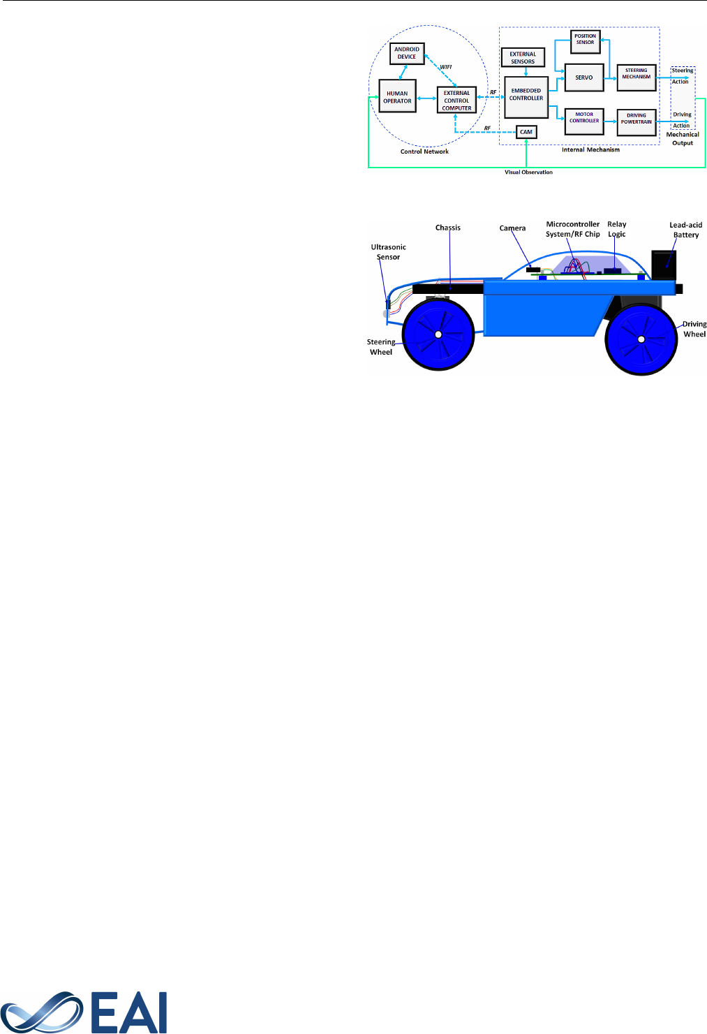
The Edu-rover robot is a software-driven system that
comprises of several subsystems that synchronously
work together to achieve the desired motion. The
Figure 1 shows the generic model of the Edu-Rover
system. This consists of a control system and an
internal mechanism. These interact precisely with each
other to drive the system. The Edu-Rover has a man-
computer machine (MCM) interface that involves an
ordinary radio frequency (RF), a wireless-fidelity (Wi-
Fi) connection, or the combination of both. These
ensemble constitutes the system’s control network.
In this network, the RF is used as the media for
information exchange between the human operator and
the vehicle’s internal mechanism through the external
control computer (ECC) within the line-of-sight (LoS),
and also for the wireless relay of video feedbacks from
the onboard video camera (i.e. CAM) to the personal
computer (PC) to enhance visual observation of the
vehicle’s terrain. The Wi-Fi is used to establish an
alternative or higher level medium for teleoperation via
internet connection between the human operator and
the ECC (while it is connected to the vehicle’s internal
Figure 1. Block Diagram of the Edu-Rover System
Figure 2. Model of the Edu-Rover system
mechanism) through a portable device like the Android
system when the human operator is beyond LoS or in
a very remote location. In this manner, the Edu-Rover
system is essentially a cyber-physical system, which
involves the flow of sensory data, control signals, and
visual/video feedback between the human operator and
the vehicle’s internal mechanism over an IoT-integrated
wireless control network.
3.1. Edu-Rover System: Design and Concepts
The Edu-Rover system is a simple rover design, which
is remotely controllable with a desktop computer to
demonstrate the "drive-by-wire" concept. The internal
mechanism of Edu-Rover is made-up of some active
components that include the driving mechanism,
steering mechanism, sensors, and a controller. A control
algorithm was formulated and used to integrate these
components into a functional mechatronic system. The
Figure 2 shows the 2D model of this system.
For navigation, Edu-Rover uses a high-torque drive
system and a servo-mechanical steering system. The
drive systems consist of a speed-reduction geared-
motor that transmits equal power to the duo-rear
wheels. The two rear driving wheels are attached to the
load shaft to convert the rotary motion of the drive-train
into the propelled linear motion of the robot, either
to the forward or reverse direction, as dictated by the
controller. Also, with the cushion effect of the rubber
material used in lining the wheels and its large area in
contact with the ground, enough traction is produced to
propel our robotic vehicle system.
3
EAI Endorsed Transactions on
Creative Technologies
12 2020 - 03 2021 | Volume 8 | Issue 26 | e2

M. S. Benyeogor et al.
The steering mechanism of Edu-Rover is a servo-
controlled Ackermann steering system – an improve-
ment on the steering design of [24]. Its design layout
and physical construction is shown in the Figure 3. Edu-
Rover is steered whenever the rotation of the steering
lever converts to the linear motion of the steering
linkage. The servo can position the steering lever in
three orientations on the horizontal plane i.e. 0°, 90°,
and 180°. If the steering lever is oriented at angle 0°,
the steered wheels turn left. At 90°, they align straight,
while at 180° they turn right, according to the Ack-
ermann steering geometry. The servo produces a stall
torque, τ
servo
of 1.0787 Nm at an angular velocity ω
servo
of 6.5440 rad/s at 5V DC supply. The steering radius
(i.e. length of the steering lever), r is 0.045 m.
The tangential force generated by the steering lever is
evaluated as
F
servo
=
τ
servo
r
=
1.0787Nm
0.045m
= 23.971N, (1)
hence, the power of the steering system is in turn
evaluated as
P
steering
= τ
servo
× ω
servo
= 7.0590W. (2)
Further details concerning the mechanics of the
Edu-Rover system is discussed in [25]. This analysis
provides a basic understanding of robot locomotion
and the underlying mechanics as a STEM concept. In
effect, this could be applied to the primary and junior
secondary education, within the context of introductory
technology, to prepare young pupils for future career
prospects in the field of vehicle design.
Figure 3. Depiction of the steering mechanism
3.2. Electrical Sub-system: Electronics and Sensors
The embedded controller of Edu-Rover is controlled
and instructed using ATmega328P microcontroller.
This is programmed as a semi-automatic controller. It
monitors its serial communication port continuously in
anticipation of radioed control signals from the human
operator through the ECC. This embedded controller
interacts wirelessly with the ECC in a master-and-slave
architecture. Here, the embedded controller functions
as the slave while the ECC functions as the Master.
The peripherals of the embedded controller include the
relay-logic motor controller, the steering servomotor,
and four navigational sensors. The navigational sensors
include an inertial measurement unit (IMU), ultrasonic
sensors, a GPS sensor, and a compass sensor as shown in
Figure 4. The relay-logic motor controller is electrically
interfaced with the embedded controller. It contains
two discrete relays that are wired together to form a
two-channel relay H-bridge as shown in Figure 5. This
can power the driving motor of Edu-Rover in either
clockwise or counter-clockwise direction. The relay-
logic powers the motor to spin clockwise if a logical
HIGH is applied to the pin IN1 and a logical LOW to
pin IN2 and, vice-versa for the driving motor to spin
counter-clockwise. The relay-logic motor controller also
functions as an electromagnetic isolator that protects
the embedded controller which runs on 5 Volts from a
24 Volts source that powers the driving motor.
Figure 4. Navigational sensors of the Edu-Rover System
Figure 5. The Relay-Logic Motor Controller (contains two relays
connected to form H-bridge circuit)
The MG995 Servo is used for the precision control
of the angular position of the steering lever, which in
turn, displaces the steering linkage to and fro, to steer
the vehicle towards the desired direction. To control the
steering system of Edu-Rover, the embedded controller
sends electrical pulses of variable width to the steering
servo, through its control wire, by a process known as
pulse width modulation (PWM). The steering servo can
only be controlled to rotate the steering lever by 90°
in either direction for a total of 180° rotation angle.
The PWM signal sent to the steering servo from the
4
EAI Endorsed Transactions on
Creative Technologies
12 2020 - 03 2021 | Volume 8 | Issue 26 | e2

Edu-Rover: Application of Unmanned Vehicle Systems for Robotics and STEM Education in Nigeria
embedded controller determines the position of the
steering lever at any instant. Based on the duration
of the pulse sent to the steering servo via its control
wire; the steering lever is rotated to the desired angular
position. The steering servo continuously anticipates a
pulse every 20 millisecond (ms) and the length of the
pulse determines the angular position of the steering
lever. A pulse of 1.5 ms will place the steering lever at
the angular position of 90°. A pulse which is shorter
than 1.5 ms (e.g. 1.0 ms) will rotate the steering lever
in the counter-clockwise direction and place it at the
angular position of 0°; while any pulse which is longer
than 1.5 ms (e.g. 2.0 ms) will rotate the steering lever
in a clockwise direction and place it at the angular
position of 180°. The Figure 6 describes this process.
The vehicle is aligned to drive in a straight line if the
steering lever is placed at the angular position of 90°.
If the steering lever is positioned at 0°, the vehicle is
steered towards the right-hand side and the left-hand
side, if the steering lever is positioned at 180°.
Figure 6. Different Pulse Widths and the corresponding Servo
angular positions and steering action(s) of the vehicle
3.3. Software Subsystem: Control Logic and
Algorithms
The software structure of Edu-Rover’s control system
comprises several embedded blocks of algorithms and
logic, which controls its operation – navigation and
perceptual responses. These include blocks of programs
for remote-controlled driving, steering, anti-collision
control, and sensory feedback. These were written
in C++ programming language and compiled onto
the embedded controller. The software structure of
Edu-Rover is described in Figure 7. The algorithms
of this software system are extensively discussed
in Sub-subsection 3.3. This encapsulates conceptual
techniques that could be used to teach object-oriented
programming (OOP), as a STEM subject. Following the
concepts in [26], some important subject-matters that
can be learned from the software system of Edu-Rover
include software organization, bit-wise programming,
physical computing, and microcontroller-based OOP.
Figure 7. Software structure of the Edu-Rover system showing
different blocks of embedded algorithms and logic
Tele-autonomous Control Algorithms. This comprises two
blocks of algorithms – the tele-driving and auto-
driving algorithm, for tele-operated and autonomous
control respectively. The former describes a selection
control structure that logically maps the command
of the remote human operator to the target control
function, at any instant of time. In this logic,
the unique American standard code for information
interchange (ASCII) characters are mapped to different
preprogrammed motions of the Edu-Rover system.
Here, the microcontroller continually observes its serial
port for incoming signal(s) and compares it to its
conditional constants, in order to execute the block
of program whose conditional constant value matches
that of the incoming signal. For instance, if a block
of programs contains statements for actuating forward
driving, the micro-controller causes Edu-Rover to move
in the forward direction for a given duration of time.
The logic of this function is described in Algorithm 1.
In the absence of serial control signal(s) from the human
operator, the robot automatically switches to the auto-
driving algorithm (i.e. autonomous mode), through the
activation of Algorithm 2, by means of function calls.
Based on the definitions of [24] and [27], the inter-
switch between Algorithm 1 and Algorithm 2 describes
the implementation of a tele-autonomous system – a
shared control between a human operator and the
computer.
Linear-motion and Steering Algorithm. To perform drive-
by-wire motions in 2D planes, the Edu-Rover software
system incorporates two motion control algorithms.
These are linear-motion algorithm (i.e. Algorithm 3)
and steering algorithm (i.e. Algorithm 4). During the
operation of the Edu-Rover system, Algorithms 3 and
4 responds to function calls (in the form of "go to"
statements) from either Algorithm 1 or 2 to perform
5
EAI Endorsed Transactions on
Creative Technologies
12 2020 - 03 2021 | Volume 8 | Issue 26 | e2

M. S. Benyeogor et al.
Algorithm 1 Tele-driving Algorithms
Require: serialPort
1: function teleDriving
2: while serialPort > 0 do ASCII code is on the
serial port
3: controlSignal ← serialPort
4: if controlSignal = ’F’ then
5: goto forward
6: continue for 1 seconds
7: goto stop
8: else if controlSignal = ’B’ then
9: goto backward
10: continue for 1 seconds
11: goto stop
12: else if controlSignal = ’S’ then
13: goto stop
14: else if controlSignal = ’G’ then
15: goto straight
16: else if controlSignal = ’Q’ then
17: goto left
18: continue for 1.5 seconds
19: goto straight
20: else if controlSignal = ’P’ then
21: goto right
22: continue for 1.5 seconds
23: goto straight
24: end if
25: end while
26: while serialPort ≤ 0 do No ASCII code on the
serial port
27: call autoDriving
28: end while
29: end function
the electrical and logical operations in Subsection 3.2.
Algorithm 3 describes a switching control structure,
whose basic function is to switch the logical states
of the 2-channel relay as shown in Figure 5 and as
so, rotates the driving motor either in the clockwise
or counter clockwise direction. The syntax of the
embedded software statements for executing linear-
motion control is given in Listing 1. This particular
statements cause the Edu-Rover system to move in the
forward direction. For the reverse motion and brake,
the logical states in Listing 1 are varied according to
Algorithm 3.
Listing 1: Forward-motion Control source codes
/* Object f o r forward dr i vin g * /
forward :
{
d i g it al W r i t e ( relay_1 , HIGH ) ;
d i g i t a l W r i t e ( relay_2 , LOW) ;
t e l e D r i v i n g ( ) ;
}
Algorithm 2 Auto-driving Algorithms
Require: proximitySensor
Require: serialPort
1: function autoDriving
2: while serialPort ≤ 0 do No ASCII code on the
serial port
3: distance ← proximitySensor
4: if distance ≤ 30cm then
5: goto stop
6: goto backward
7: continue for 1.5 seconds
8: goto stop
9: goto left
10: goto forward
11: continue for 1.5 seconds
12: call autoDriving
13: else if 30cm < distance ≤ 60cm then
14: goto stop
15: goto backward
16: continue for 1 seconds
17: goto stop
18: goto right
19: goto forward
20: continue for 1 seconds
21: call autoDriving
22: else if distance ≥ 90cm then
23: goto forward
24: end if
25: end while
26: while serialP ort > 0 do ASCII code on the
serial port
27: call teleDriving
28: end while
29: end function
To control the steering system of Edu-Rover, the
branches in Algorithm 4 are consecutively called by
Algorithm 1 or Algorithm 2 to execute the motion
schedule. This involves the variation of the steering
angle according to Figure 6. The syntax of embedded
software statements for executing steering control are
given in Listing 2. This particular statements cause the
Edu-Rover system to steer towards the left. To drive
straight or steer towards the right side, the steering
angle in Listing 2 is varied according to Algorithm 4.
Analogous to the conventional computer system,
the input-processing-output characteristics of the Edu-
Rover software system describes how electrical signals
(i.e. inputs) from the keyboard and sensors are used to
control the motion (i.e. output) of a mechanical system,
through the computer (i.e. processor). Thus, providing
an intuitive understanding of how the computer system
works.
6
EAI Endorsed Transactions on
Creative Technologies
12 2020 - 03 2021 | Volume 8 | Issue 26 | e2

Edu-Rover: Application of Unmanned Vehicle Systems for Robotics and STEM Education in Nigeria
Listing 2: Steering control source codes
/* Obje ct f o r s t e e r i n g to the l e f t * /
l e f t :
{
s t e e r i n g . w ri te ( 1 8 0 ) ;
t e l e D r i v i n g ( ) ;
}
Algorithm 3 Linear-motion Algorithm
Input: goto ⇒ f orward, backward, stop
Output: Logical_States
Output: call ⇒ teleDriving
1: procedure Relay Switching Controls drive motor
2: forward:
3: Relay_1 ← 1
4: Relay_2 ← 0
5: call teleDriving.
6:
7: backward:
8: Relay_1 ← 0
9: Relay_2 ← 1
10: call teleDriving.
11:
12: stop:
13: Relay_1 ← 0
14: Relay_2 ← 0
15: call teleDriving
16: end procedure
Algorithm 4 Steering-control Algorithm
Input: goto ⇒ straight, lef t, right
Output: pulseW idth ⇒ steeringAngle
Output: call ⇒ teleDriving
1: procedure Servo Signaling Turns steering angle
2: straight:
3: SteeringAngle ← 90
◦
4: call teleDriving.
5:
6: left:
7: SteeringAngle ← 180
◦
8: call teleDriving.
9:
10: right:
11: SteeringAngle ← 0
◦
12: call teleDriving.
13: end procedure
3.4. Control Architecture
For the operation of Edu-Rover as an IoT device, we
provided the control model in Figure 8. This allows
it to integrate an internet-enabled ECC for both LoS
and beyond LoS control. The later control channel
involves an internet connection between ECC and
third-party hardware (e.g. an Android device). This
becomes useful whenever the human operator needs to
drive Edu-Rover from a remote location. Thus, we can
reconfigure the Edu-Rover system to have two inter-
system communication interfaces. The first interface
is the wireless communication between Edu-Rover’s
internal mechanism and the ECC, while the second
one is between the ECC and the human operator
(which alternatively involves the Internet as earlier
mentioned). In this configuration, the ECC only acts as a
gateway between the vehicle’s internal mechanism and
the outside world.
Figure 8. Edu-Rover Control Architecture
4. Results, Application, and Discussion
Using the available materials and technology in the
Nigerian environment, we prototyped Edu-Rover as an
unmanned vehicle system and demonstrated it before
different groups of students in several workshops to
ascertain its applicability as an instructional apparatus.
During the demonstration of Edu-Rover, the students
performed test procedures with Edu-Rover. We also
examined their knowledge of its working principles
to ascertain the pedagogical significance of Edu-
Rover. The Edu-Rover vehicle was assembled and
demonstrated to the students as shown in Figure
9. We issued questionnaires to two sets of 105
participating students at the completion of their hands-
on exercises to rate on a scale of zero to ten how
Edu-Rover system improved their STEM knowledge.
This questionnaire was restricted to their knowledge of
Physics, Mathematics, and Computing, which underlies
our Edu-Rover system. The bar chart in Figures 10 and
11 are the graphical representations of the results. Also,
a survey was carried out to determine the interest of
participant teachers in the application of Edu-Rover to
their subjects of specialization. The result of this study
is shown in Figure 12.
From the Figures 10 and 11, it is palpable that
a larger proportion of the students preferred the
7
EAI Endorsed Transactions on
Creative Technologies
12 2020 - 03 2021 | Volume 8 | Issue 26 | e2

M. S. Benyeogor et al.
(a) The developed system (b) STEM-based teaching (c) Technical demonstration
Figure 9. Live Exhibition of Edu-Rover to the students in a robotics experimentation session
1 2 3
4
5 6 7 8 9 10
0
5
10
15
20
Ratings
Number of Students
Physics
Mathematics
Computer Science
Figure 10. Sample-1: Students Course Assimilation Ratings
using Edu-Rover
1 2 3
4
5 6 7 8 9 10
0
5
10
15
20
Ratings
Number of Students
Physics
Mathematics
Computer Science
Figure 11. Sample-2: Students Course Assimilation Ratings
using Edu-Rover
adoption of Edu-Rover as an instructional apparatus
for STEM education, with Computer Science at the
leading edge. This they say, could help them to visualize
and physically experience the science and engineering
theories they have been learning. The implementation
of this project by each team helped to recall and
enhance their knowledge in the Mathematics of the
system, Physics of the mechanism, and Computer
Science underlying the control algorithms. From Figure
12, it can be deduced that the application of Edu-
Rover for STEM education would have higher impact
on Computer Science and Engineering in relation to
other STEM subjects; which unsurprisingly, are the
two major disciplines upon which future advances
in robotics and automation would apply. Also, some
participant teachers suggested that our Edu-Rover is
useful and applicable for teaching and demonstrating
the rudiments of automotive technology in schools,
which could significantly prepare talented pupils for
a future career in the emerging field of autonomous
vehicle systems.
5. Conclusion
In this paper, we discussed the need for practice-
oriented STEM education in schools, with a focus on the
observed inadequacy of hands-on learning technology
in Nigerian schools. Based on our current development,
we hereby propose and advocate a step towards
the improvement of STEM education; through the
introduction of hands-on robotics to school curricula.
We implemented an unmanned robot-vehicle prototype
to this effect. This involved the physical implementation
of Edu-Rover and a mock adoption of the system for
teaching STEM concepts. Here, we made use of the
materials that are easily accessible in the Nigerian
environment to show that the schools can actually
start the introduction of robotics education on a low
budget phase. Questionnaire data were collected from
the participating students, to ascertain how the Edu-
Rover influences their conceptualization of Physics,
8
EAI Endorsed Transactions on
Creative Technologies
12 2020 - 03 2021 | Volume 8 | Issue 26 | e2

Edu-Rover: Application of Unmanned Vehicle Systems for Robotics and STEM Education in Nigeria
Physics
10%
Mathematics
10.8%
Computer Science
51.6%
Engineering
20%
Art
7.6%
Figure 12. Classification of teachers’ interests according to subjects of specialization
Mathematics, and Computer Science subjects. From the
results, we observed that the Edu-Rover system and
the associated didatics excited their enthusiasm in the
application-oriented field of robotics, and as such, can
be inculcated into STEM education in schools. Also,
our initiative has motivated the students’ enthusiasm
to delve into the fields of Computing and Robotics.
We therefore recommend that further research in
this area be focused on the development of robotics
curriculum and standard laboratory robots for teaching
and learning purposes, especially in Nigerian schools.
With this, we could envisage that Nigeria in no time,
would join the league of technologically advanced
countries of the world.
References
[1] Lynch, K. and Park, F. (2017) Modern robotics:
Mechanics, planning and control. Cambridge University
Press .
[2] Benitti, F. (2012) Exploring the educational potential of
robotics in schools: A systematic review. Computers and
Education 58(3): 978 – 988.
[3] Nagai, K. (2001) Learning while doing: Practical robotics
education. IEEE Robotics Automation Magazine 8(2): 39–
43.
[4] Hagedorn, L. and Purnamasari, A. (2012) A realistic
look at STEM and the role of community colleges. Sage
Journals 40(2): 145–164.
[5] FIRST (2019), FIRST robotic competition,
https://www.firstinspires.org/robotics/frc. Accessed
on 11
th
August, 2020.
[6] Harnden, P. (2019), Moon landing remem-
bered in the FIRST robotic competition,
https://www.sunjournal.com/2019/01/08/moon-
landing-remembered-in-first-robotics-competition/.
Accessed on 11
th
August, 2020.
[7] Steele, R.D., Leon, M.J. and Lavery, D.B. (2014) Curios-
ity connections with pre-college robotics competitions.
In Proceedings of Geological Society of America Annual
Meeting, Vancouver .
[8] Oni, Z. (2017), Nigeria not prepared for
robotics education, stakeholders warn,
http://www.thepointng.com/nigeria-not-prepared-
for-robotics-education-stakeholders-warn/. Accessed on
11
th
October, 2020.
[9] Kofoworola, B.O. (2017), Ezekwesili calls for radical
education, https://thenationonlineng.net/ezekwesili-
calls-radical-education/. Accessed on 12
th
September,
2020.
[10] Imade, K. (2017), U .S. promotes stem education in
nigeria, trains 460 students, teachers on robotics,
https://ng.usembassy.gov/u-s-promotes-stem-
education-nigeria-trains-460-students-teachers-
robotics/. Visited on 12
th
November, 2020.
[11] Egbedi, H. (2015), At this Nigerian school, all they
do is build robots, http://venturesafrica.com/at-this-
nigerian-school-all-they-do-is-build-robots/. Visited on
11
th
November, 2020.
[12] Seiler, S., Sell, R. and Ptasik, D. (2012) Embedded
system and robotic education in a blended learning
environment utilizing remote and virtual labs in the
cloud. International Journals of Emerging Technologies in
Learning 7(4): 26–33.
[13] Miglino, O., Lund, H. and Cardaci, M. (1999) Robotics
as an educational tool. Journal of Interactive Learning
Research 10(1): 25–47.
[14] Cox, D.J. and Schonning, A. (2006) Engineering
education via robotics, mechatronics, and automation
projects. In 2006 World Automation Congress (IEEE
Press).
[15] Silk, E. and Shcunn, C. (2007) Using robotics to teach
mathematics: Analysis of a curriculum designed and
implemented. in Proceedings of American Society for
Engineering Association 2008 Annual Meeting, Pittsburgh,
PA .
9
EAI Endorsed Transactions on
Creative Technologies
12 2020 - 03 2021 | Volume 8 | Issue 26 | e2

M. S. Benyeogor et al.
[16] He, Y. and Liang, L. (2019) Application of robotics in
higher education in industry 4.0 era. Universal Journal of
Educational Research 7: 1612 – 1622.
[17] Sezgin-Ersoya, S. and Küçüka, H. (2007) The effect of
a new teaching methodology on learning performances
of automotive - mechatronics students. in Procedia Social
and Behavioral Sciences 2: 310–316.
[18] Qidwai, U., Riley, R. and El-Sayed, S. (2013) Attracting
students to the computing disciplines: A case study of a
robotics contest. In Procedia Social and Behavioral Sciences
102: 520–531.
[19] Hernandez-Alcantara, D. and Morales-Menendez,
R. (2016) Experimental platform for teaching control
of automotive suspension. International Federation of
Automatic Control 49(6): 372–377.
[20] Prayaga, L., Prayaga, C., Wade, A. and Whiteside, A.
(2013) The design and implementation of telerobotics in
education (tre) to engage students in stem disciplines
- including computer science and physics. Journal of
Computing Sciences in Colleges 29(2): 205–211.
[21] Modeflight (2018), STEM education and
the use of radio control (RC) products,
https://www.modelflight.com.au/blog/stem-education-
and-the-use-of-radio-control-rc-products. Accessed on
1
st
August, 2020.
[22] Barford, V. (2014), Do children’s toys influence their
career choices?, https://www.bbc.com/news/magazine-
25857895. Accessed on 5
th
August, 2020 .
[23] Draxler, B. (2013), Teaching kids to think like
engineers, https://www.discovermagazine.com/the-
sciences/teaching-kids-to-think-like-engineers.
Accessed on 9
th
August, 2020.
[24] Olakanmi, O. and Benyeogor, M. (2019) Internet based
tele-autonomous vehicle system with beyond line-of-
sight capability for remote sensing and monitoring.
Internet of Things 5: 97–115.
[25] M. Benyeogor, O.O. and Kumar, S. (2020) Design
of quad-wheeled robot for multi-terrain navigation.
Scientific Review 6(2): 14–22.
[26] Douglas, B. (2005) Software Engineering for Students: A
Programming Approach (Addison-Wesley).
[27] Borenstein, J. and Koren, Y. (1990) Tele-autonomous
guidance for mobile robots. In in Proc. IEEE Transactions
on Systems, Man, and Cybernetics, Special Issue on
Unmanned Systems and Vehicles, 20(6): 1437–1443.
10
EAI Endorsed Transactions on
Creative Technologies
12 2020 - 03 2021 | Volume 8 | Issue 26 | e2
