
Pure Appl. Chem. 2017; 89(10): 1459–1469
Conference paper
Ekaterina Semenova, Daria Navolotskaya and Sergey Ermakov*
Interrupted amperometry: the new possibilities
in electrochemical measurements
DOI 10.1515/pac-2017-0302
Abstract: Interrupted amperometry is a new highly sensitive method for diffusion current measuring. The
main feature of the proposed technique is the use of capacitive current as the analytical signal together with
the faradaic current. The conventional electrical circuit for amperometric measurements is complemented
by a switcher that enables periodical interruption of the circuit. The technique was successfully applied for
direct amperometric determination of lead, cadmium and iron ions, phenol and hydroquinone; for determi-
nation of dichromate ion via titration; for determination of dissolved oxygen in water by Clark-type sensor.
In all the mentioned cases the achieved values of analytical characteristics are significantly better than
for conventional amperometric methods. There are limitations and perspectives of the proposed technique
considered.
Keywords: amperometry; analytical chemistry; aqueous solutions; chemical sensors; electrochemistry;
electrodes; heavy metals; iron; Mendeleev XX; oxygen; phenol; sensitivity; trace elements.
Introduction
Amperometry and voltammetry are powerful tools of analytical chemistry, including electrochemical
sensors [1–4], detection in chromatography [5–7], flow analysis [8–10], titration [11, 12], etc. Sensitivity of
these methods is defined by the signal-to-noise ratio [13, 14]. Traditionally, the signal is associated with the
diffusion controlled faradaic current produced by the charge transfer reaction of the analyte. The residual
current, consisting of the capacitance or the charging current and the faradaic currents caused by the reduc-
tion or oxidation of electroactive impurities, are conventionally referred to the noise. The capacitance current
appears to be the main interference. Thus, the increase in sensitivity in voltammetry and amperometry is
usually achieved by reduce of the capacitance current or by magnification of the faradaic current. One can
distinguish two general approaches to enhancing the signal-to-noise ratio – mathematical and instrumental
methods (see Table 1).
Mathematical techniques operate with experimentally collected data, and effectively eliminate noise-
like signals thus improving sensitivity and resolution. However, these methods do not improve the analyti-
cal signal physically. Moreover, in some cases signal processing can result in the loss of a useful part of
the current. Separation of the capacitance and faradaic currents is realized in instrumental methods based
Article note: A collection of invited papers based on presentations at the XX Mendeleev Congress on General and Applied
Chemistry (Mendeleev XX), held in Ekaterinburg, Russia, September 25–30 2016.
*Corresponding author: Sergey Ermakov, Saint-Petersburg State University, Institute of Chemistry, Department of Analytical
Chemistry, Saint-Petersburg, Russian Federation, e-mail: s.ermak[email protected]
Ekaterina Semenova and Daria Navolotskaya: Saint-Petersburg State University, Institute of Chemistry, Department of Analytical
Chemistry, Saint-Petersburg, Russian Federation
© 2017 IUPAC & De Gruyter. This work is licensed under a Creative Commons Attribution-NonCommercial-NoDerivatives
4.0International License. For more information, please visit: http://creativecommons.org/licenses/by-nc-nd/4.0/

1460
E. Semenova etal.: Interrupted amperometry: the new possibilities in electrochemical measurements
on time- and phase-selective current measurements. Various stripping techniques provide great sensitivity
because of the faradaic current magnification due to analyte preconcentration.
A fundamentally new approach to enhancing the signal-to-noise ratio in amperometry was first pro-
posed by Moshkin and Khustenko in 2012 [46]. The idea is to include the capacitive current in the analytically
useful part of the signal together with the faradaic current. Technically this is realized by adding a switcher
to the conventional electrical circuit for amperometric measurements. That way the measuring circuit is peri-
odically interrupted and the structure of the analytical signal becomes more complicated. The new method
was called “interrupted amperometry” (IA) [47]. Here we present a short review of its analytical applications
based on our recent studies and discuss its possibilities for analytical chemistry.
The principle of interrupted amperometry
The theoretical consideration of interrupted amperometry as well as the design of the original home-made
potentiostat “ComPot” were given in detail in our previous work [47]. Here we present only the key points of
the theory that are essential for understanding the principle of the method under consideration. The scheme
of the measuring electrical circuit for interrupted amperometry is presented on Fig. 1.
We assume that the measurement is performed under stationary diffusion of a depolarizer and the
polarizing potential difference is constant and belongs to the limiting current potential region, i.e. the dif-
fusion flow to the working electrode is constant. In this case the circuit part consisting of the serially con-
nected charge transfer resistance (R
t
) and the Warburg impedance (W) can be replaced by the value of direct
current:
Fig. 1:(a) General scheme of the measuring electrical circuit for interrupted amperometry. (b) Simplified circuit for the locked
state. (c) Simplified circuit for the opened state. P, potentiostat providing the polarizing voltage; R
S
, total ohmic resistance of
electrochemical cell; R
t
, charge transfer resistance; C
d
, double layer capacity; W, Warburg impedance; S, switcher; I
m
(t), meas-
ured current; I
d
, direct current of electrochemical reaction; I
l
(t), current emerging in the outer circuit path at the locked state;
I
o
(t), double layer discharging current at the opened state.
Table 1:Main approaches to enhancing the signal-to-noise ratio.
Mathematical methods Instrumental methods
– Derivative voltammetry [–]
– Fourier transformation [–]
– Wavelet transformation [–]
– Time-selective current measurements:
– Pulse voltammetry [–]
– Differential pulse voltammetry [, ]
– Square-wave voltammetry [–]
– Phase-selective current measurements:
– Alternating current [–], including sinusoidal voltammetry [–]
– Stripping techniques [–]
– Interrupted amperometry [–]

E. Semenova etal.: Interrupted amperometry: the new possibilities in electrochemical measurements
1461
0
,
dx
D
I
nFAC=
δ
(1)
where n is the number of electrons, involved in electrochemical reaction; F is the Faraday constant; A is the
surface area of the working electrode; D is the diffusion coefficient; δ is the thickness of the Nernst diffusion
layer;
0
x
C
is the bulk concentration of the analyte.
The switcher (S) locks the circuit for the period of time t
l
(µs) and then opens the circuit for the period of
time t
o
(ms). The sum of these times is called “the period of switching”:
.
lo
Ttt
=+
(2)
The switching is performed during the entire experiment. After several first periods the full charging of
the capacitor (C
d
) is achieved. Then at every locking of the circuit the capacitor is recharged by the current
I
l
(t), that emerges in the outer circuit path. At every opening of the circuit the double layer (DL) partially
discharges. This process produces the current I
o
(t) that supports the current of electrochemical reaction.
Recharging and discharging of the capacitor are repeated until a stationary state is achieved. This state is
characterized by the current I
m
(t) that can be measured in the outer circuit path when the switcher locks the
circuit. The average value of I
m
(t) is used as analytical signal and is proportional to the diffusion current pro-
duced by the analyte discharge:
.
md
l
T
I
I
t
=
(3)
The T/t
l
ratio serves as an amplification factor and usually its value is of several orders. However, this
coefficient practically amplifies not only the analytically useful diffusion current I
d
, but also all the noise cur-
rents I
i
produced by interfering processes. Therefore, the expression (3) should be written as follows:
()
,
mdi
l
T
I
II
t
=+
∑
(4)
where I
i
are interfering currents depending on the experimental conditions and set up.
Experimental
Electrochemical measurements were performed using a home-built computer controlled potentiostat
“ComPot” that allows to work in direct-current and interrupted-current modes. High-performance potentio-
stat provides transition time of not more than 10 µs. The device offers the opportunity to compensate of the
initial current.
All electrodes were supplied by Metrohm (Switzerland), unless otherwise is indicated in the text below.
Measurements were carried out at room temperature in a Faraday cage. The reagents used were of analyti-
cal grade. All aqueous solutions were prepared using deionized water of resistivity 18.2 MΩ cm (25 °C, D-301
deionizer, Akvilon, Russia).
Ideal case: the determination of cadmium and lead at the static
mercury drop electrode by direct IA
Mercury electrodes are often referred to as the “ideal” working electrodes [14]. In case of an ideally polarized
electrode the applied charge is fully utilized to DL charging in a wide potential range. Usually electrochemi-
1462
E. Semenova etal.: Interrupted amperometry: the new possibilities in electrochemical measurements
cal reactions occurring at mercury electrodes are not affected by side reactions. Thus, the expression for the
measured current (4) in case of mercury electrode usage as a working electrode for IA measurements can be
transformed into a rather simple form:
imp
()
,
md tr
l
T
I
II I
t
=++
(5)
where I
imp
is the current caused by the reduction or oxidation of electroactive impurities, I
tr
is the transition
current corresponding to the process of potential setting after switching. If the transition time of potentiostat
is at least ten times less than the locking time, the value of I
tr
becomes negligible. The potentiostat used for
IA measurements provides the transition time of not more than 10 µs. So, the latter summand in equation (5)
can be neglected. Therefore, the interfering (or noise) current occurs only because of the presence of electro-
active impurities in case of mercury electrode. That’s why the first analytical experiments with interrupted
amperometry were performed at the fine static mercury drop electrode (SMDE). The choice of model analytes,
namely cadmium and lead, is explained by their high toxicity and abundance [49, 50], and hence, the high
relevance of their determination in environmental analytical chemistry.
Cadmium (II) and lead (II) ions were determined in aqueous solutions via interrupted amperometry
in direct mode. The measurements were carried out in a three-electrode cell of VA Computrace analyzer
(Metrohm, Switzerland) attached to the potentiostat “ComPot”. The cell consisted of the static mercury drop
working electrode (drop size ca. 0.6mm
2
), silver/silver chloride reference electrode with double junction and
platinum counter electrode. Stirring was provided by a mechanical rod stirrer with the speed of 1600rpm.
Supporting electrolyte was acetate buffer solution with pH 5. The following timing parameters were used:
locking time t
l
= 100 µs, opening time t
o
= 300ms. Amperometric measurements were conducted at the poten-
tial belonging to the limiting current potential region. Preliminary voltammetric experiments showed that
the proper detection potential for cadmium (II) ions is −0.60 V (vs. silver/silver chloride electrode), for lead
(II) ions – −0.40 V.
Ultrasensitive electrochemical methods of analysis require extra attention to the presence of even the
smallest amounts of electroactive impurities, primarily dissolved oxygen. In order to study the influence of
oxygen presence on IA measurements amperograms were recorded with additions of deionized water satu-
rated by atmospheric oxygen (black line of Fig. 2) and with additions of the standard solution containing
cadmium (II) ions (red line of Fig. 2).
–30
–40
–50
–60
–70
–80
100 200 300 400
Time (s)
Cathodic current (mkA)
500 600 700
800
a
b
c
d
Fig. 2:The influence of dissolved oxygen presence on IA measurements. a (black) – Amperogram obtained with additions of
deionized water saturated by atmospheric oxygen. b (red) – Amperogram obtained with standard additions of Cd
2+
solution. c
(blue) – Amperogram obtained with standard additions of deoxygenated Cd
2+
solution. d (pink) – Amperogram obtained with
standard additions of deoxygenated Cd
2+
solution. The area above the solution was blown with argon during the measurement.

E. Semenova etal.: Interrupted amperometry: the new possibilities in electrochemical measurements
1463
As it can be seen in Fig. 2, the obtained amperograms have similar forms. This means that the standard
solution of Cd
2+
needs to be released from oxygen. Therefore, all standard solutions used for direct IA meas-
urements were bubbled with ultrapure argon for at least 40min prior to their use.
Amperogram obtained with additions of the standard Cd
2+
solution after the described procedure was
recorded in a more sensitive current range (see the blue “c” line of Fig. 2). However, the continuous current
drift does not allow us to identify stairs corresponding to the additions of the analyte. This stable current
decrease was caused by oxygen present in the area above the solution in the measuring cell. In order to elimi-
nate this interference the described area was blown by ultrapure argon during direct IA measurements. As
a result, amperogram was obtained with well-defined stairs each corresponding to the standard addition of
Cd
2+
ions (the pink “d” line of Fig. 2).
The analytical possibilities of the proposed technique for determination of lead and cadmium at
SMDE were evaluated. It was found that the dependence of the measured current on Cd
2+
concentration
is linear in the range from 1 till 200nM (y = 10
9
x + 17.599, r
2
= 0.998) and for Pb
2+
ions – from 5 till 200nM
(y = 2*10
9
x + 9.2191, r
2
= 0.995). Practical limits of detection (LOD), calculated as three times the signal to
noise ratio, are 0.26nM and 0.79nM for cadmium (II) and lead (II) ions respectively. These LOD values are
typical for the present-day stripping techniques utilizing amalgam concentration [51], but are quite remark-
able for direct amperometry.
General case: interrupted amperometry using solid electrodes
The use of mercury electrodes in the practice of analytical chemistry is often associated with some experi-
mental manipulation difficulties. That is why it is important to consider the application of solid working
electrodes for IA measurements.
Solid electrodes are characterized by the significantly narrower region of the ideal polarizability. In this
case the applied charge is utilized not only for DL charging but also for various processes associated with
the charge transfer. In general case the residual current is related to all the processes occurring at the elec-
trode-solution interface. The following processes can appear when we use solid electrodes: electrochemi-
cal dissolution of electrode material; formation of oxide films; adsorption of solvent components (oxygen
and hydrogen for water); electrochemical instability of solvents (release of oxygen in the anodic region and
release of hydrogen in the cathodic region for water). Consequently, the sensitivity of IA measurements is
influenced by the magnitude of the current associated with non-ideal polarizability of working electrode and
the current caused by reduction or oxidation of electroactive impurities, since current types are not depend-
ent on the analyte concentration, but are dependent on the gain value. That is why the expression (4) for the
measured current in general case can be presented as following:
impnonid
()
,
md
l
T
I
II I
t
=++
(6)
where I
nonid
is the current associated with various processes occurring on the electrode surface and respon-
sible for its non-ideal polarizability. Therefore, when planning an IA experiment it is important to select the
material of the working electrode that is characterized by the minimum value of background current in the
area of analyte’s detection potential. We used solid electrodes for the direct IA determination of hydroqui-
none, phenol and iron.
The determination of hydroquinone and phenol
The determination of hydroquinone was carried out in a three-electrode cell using phosphate buffer
solution (PBS) with pH 6.9 as a supporting electrolyte. The reference electrode was silver/silver chloride

1464
E. Semenova etal.: Interrupted amperometry: the new possibilities in electrochemical measurements
electrode and the auxiliary electrode was a glassy carbon crucible. The following electrodes were con-
sidered as working: rotating disk electrodes made of gold, platinum, and glassy carbon (S = 0.78mm
2
)
and polymeric polyethylene- and carbon-based composite electrode (Tom’analit, Tomsk) (S = 1.96mm
2
).
In order to choose the optimum material of the working electrode, dependences of current density on
potential were registered using all of the mentioned electrodes. The obtained results are summarized in
Fig. 3.
These voltammograms were registered at the stepwise potential sweep. The interrupted mode of the
measurements requires the presence of at least one period of switching during a step. Consequently, the
sweep rate for the specified period of switching (100ms/100 µs) should not exceed 4mV/s. In order to
obtain sufficiently detailed voltammograms we used 1mV/s sweep rate. Three regions (roughly indicated
by two vertical solid lines on Fig. 3) can be distinguished for the four presented graphs. In the first region,
a sharp decrease and then an increase in current is observed due to the charging of DL capacitance and
also to the attainment of the initial potential value. The second region is a plateau and hence it corre-
sponds to the working region of the electrode. In the third region a smooth but considerable increase in the
background current is likely associated either with electrochemical decomposition of the solvent or with
electrochemical corrosion of the working electrode material. We compared the values of current density
in the limiting current potential range (from 0.5 till 0.9 V) of hydroquinone. As it can be found on Fig. 3
the least residual current related to non-ideal polarizability of electrode is demonstrated by the composite
electrode. Consequently, the use of this electrode can provide more sensitive determination as compared
with the other electrodes under study. The polymeric carbon-based electrode was, thus, selected as the
optimum for quantitive hydroquinone determination. The analogous experiment described in [48] was
conducted using a 1 % solution of sulfuric acid as a supporting electrolyte for selecting the most suitable
electrode for phenol determination. It was found that in this case, the composite electrode is the most
appropriate too.
Analytical characteristics of direct IA for the quantitive determination of hydroquinone and phenol
using the polymeric carbon-based composite electrode were evaluated. It was shown that the dependence of
the measured current on phenol concentration is linear in the range from 0.5 till 3 µM, and from 0.1 till 5 µM
for hydroquinone. Limits of detection calculated using the 3σ-criterion were found to be 8.8 nM for phenol
and 0.3nM for hydroquinone. It should be noted that these LOD values are characteristic for amplification
factor of 4000, i.e. for the specified period of switching. Sensitivity is defined by the slope of the linear
region of calibration curve and reached the value of 76 nA/µM for phenol determination and 75 nA/µM for
hydroquinone [48].
50
0
–50
–100
–150
0 250 500
Potential (mV)
123
a
b
c
d
Current density (mkA*mm
–2
)
750 1000
Fig. 3:Selection of the working electrode material for hydroquinone determination. Voltammograms were obtained using:
a–platinum electrode; b – gold electrode; c – glassy carbon electrode; d – polymeric carbon-based composite electrode.

E. Semenova etal.: Interrupted amperometry: the new possibilities in electrochemical measurements
1465
The determination of iron
The similar approach to the selection of the working electrode material was applied for the determination of
iron. Cyclic voltammograms were registered using carbon and gold RDE of the same 2mm diameter in blank
supporting electrolyte solutions and in solutions containing Fe
3+
ions. The obtained curves are shown in
Fig.4. If we compare the values of the residual current registered on blank voltammograms in the regions of
limiting current, for example, at +0.1 V in case of carbon RDE (see the black “a” line on Fig. 4) and at +0.7 V
in case of gold RDE (see the blue “c” line of Fig. 4), we can notice the difference of about one thousand times.
On the one hand, this means that the preferable electrode for iron determination is carbon RDE. On the other
hand, the used potentiostat is able to compensate of the initial current, thus, providing additional possibili-
ties for sensitivity enhancing. Therefore, analytical characteristics were evaluated for iron determination at
both carbon and gold RDEs.
Determination of iron (III) at a carbon rotating disk electrode (RDE) in aqueous solution by direct IA
is described in [47]. It was found that the theoretical limit of detection calculated from the calibration plot
is 3 nM. The calibration curve is linear in the whole investigated concentration range from 0.02 to 0.38 µM
and gives a value of 1.22 µA µM
−1
for the sensitivity. These promising characteristics were compared with the
values obtained in conventional direct-current amperometry mode with other experimental conditions being
the same: 0.2 µM and 0.81 nA µM
−1
for LOD and sensitivity, respectively. The accuracy verification of the pro-
posed technique showed that it does not produce any significant systematic errors.
Similar experiment was performed at gold RDE as a working electrode for iron (III) determination. Silver/
silver chloride reference electrode and platinum counter electrode were used. Supporting electrolyte was
0.1M HCl prepared by the dilution of concentrated ultrapure hydrochloric acid with deionized water. Detec-
tion potential was held at +0.70 V. Locking time was 100 µs and the period of switching was 300ms. Calibra-
tion plot (y = 10
9
x + 36.947, r
2
= 0.9995) obtained under stated conditions by the method of standard additions
was found to be linear in the concentration range from 0.01 till 1 µM of Fe
3+
ion. The practical LOD reached the
value of 2.5 nM, which is very close to the theoretical LOD obtained at carbon RDE. The proposed technique
was tested on real samples of Baltic Sea bottom water. After acidic microwave-assisted sample preparation
these 11 water samples were analyzed by IA and electrothermal atomic absorption spectroscopy (ETAAS)
using AA-7000 spectrophotometer (Shimadzu). Results obtained by these two methods are presented in
Table2 and show good agreement with each other. This means that direct IA can be successfully applied in
practical analytical chemistry.
6000
4000
2000
0
–2000
–4000
–6000
–8000
0 200 400
Potential (mV)
Current (nA)
600 800
a
b
c
d
Fig. 4:Selection of the working electrode material for iron determination. a – Cyclic voltammogram obtained using a carbon
RDE in 0.1M nitric acid as supporting electrolyte without any additions, b – voltammogram registered after a standard addition
of Fe (III) ion. c – Background voltammogram obtained using gold RDE in 0.1M hydrochloric acid, d – voltammogram registered
after a standard addition of Fe (III) ion. The sweep rate in all cases is 50mV/s.

1466
E. Semenova etal.: Interrupted amperometry: the new possibilities in electrochemical measurements
Interrupted amperometric titration: the determination
of dichromate ion
In amperometric titration the influence of the working electrode material is not as significant as in direct
amperometry, because the value of the measured current is of interest only as an indicator. The shape of titra-
tion curve depends on the role of electrochemically active substance, which can be analyte, titrant or their
reaction product [14]. One of the assumptions made for theoretical consideration of IA in our previous work
[47] stated that the concentration of a depolarizer is so low, that the current of electrochemical reaction is
much lower than the DL charging current. This condition is easily fulfilled when an electrochemically inac-
tive substance is titrated by electrochemically active titrant.
A well-known technique for determination of dichromate ions based on their reduction by iron (II) ions
[52] was used as a model system in order to investigate the possibilities of IA in titration mode. The measur-
ing electrochemical cell consisted of platinum RDE (diameter 2.0mm, rotation speed 2000rpm) as a working
electrode, platinum rod as a counter electrode and a silver/silver chloride reference electrode. The potential
was held at +1.0 V (vs. silver/silver chloride electrode) and amplification factor was 1000. A standard 0.01M
solution of ammonium iron (II) sulfate served as titrant. Both titrant and model analyte solutions were deoxy-
genated by argon prior to measurements.
The end point is found graphically as the point of intersection of the “residual current” line before the
end point and of the anodic diffusion current line of the ferrous iron after the end point (see Fig. 5b). Prelimi-
nary studies showed that the acceptable value of the error (±0.7 %) is achieved when the concentration of
dichromate ion is not less than 1.68 µM.
Table 2:Concentration (C) of Fe
3+
ion determined by ETAAS and IA in the samples of Baltic Sea bottom water (n=2, P=0.95).
Sample # ETAAS results, (C±ΔC) µg L
−
IA results, (C±ΔC) µg L
−
LLA .±. .±.
F .±. .±.
LL .±. .±.
P .±. .±.
NAR .±. .±.
F .±. .±.
LL .±. .±.
GF .±. .±.
F .±. .±.
LL .±. .±.
LL .±. .±.
35
ab
30
25
20
15
Current (mkA)
Current (mkA)
10
5
0
30
25
20
15
10
5
0
0 250 500 750
Time (s) Volume (mL)
0.0 0.5 1.0 1.5 2.0 2.5
1000 1250
Fig. 5:Typical amperogram (a) and the corresponding titration curve (b) obtained with IA detection.

E. Semenova etal.: Interrupted amperometry: the new possibilities in electrochemical measurements
1467
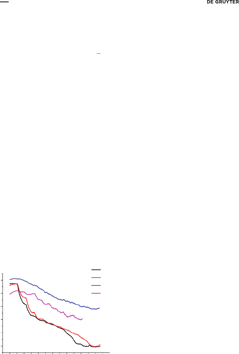
Using of direct interrupted amperometry in a Clark-type sensor
The use of direct IA for detection in electrochemical sensors is of particular interest. This approach was
applied to determine concentration of dissolved oxygen in water by Clark-type sensor. The problem of the
ultrasensitive determination of dissolved oxygen in high-purity aqueous media is topical, for example, in
thermal and nuclear power industry [53]. Therefore, ultrapure water obtained by the ion-exchange deioniza-
tion of distilled water, being in equilibrium with atmospheric air, was taken as a model sample to be ana-
lyzed. Changing the concentration of dissolved oxygen was achieved by adding fixed amounts of sodium
sulfite. This procedure provided decrease in O
2
concentration to the required value due to a redox reaction.
The experimental setup was assembled as follows. Two sensors were immersed in a 300mL beaker filled with
deionized water. The first was Clark-type oxygen sensor AKPM-02 (“Al’fa BASSENS” Company OOO, Russia)
attached to “ComPot” potentiostat. The second sensor was a part of commercially produced MARK-302T
oxygen meter (“VSOR” Company OOO, Russia) that was used as a reference device. The beaker was placed on
a magnetic stirrer and covered with laboratory film “Parafilm” (“Pechiney Plastic Packaging”) that did not
allow oxygen inflow. Additionally, the area above the water in the beaker was blown with ultrapure argon.
Amplification factor of 1000was used in direct IA-mode and detection potential was −0.7 V. After a constant
response was achieved from both MARK-302T oxygen meter and “ComPot” potentiostat, we started to lower
the concentration of dissolved oxygen by successively adding 10mg portions of sodium sulfite. As a result
a chronoamperogram presented on Fig. 6a was registered and a calibration plot (see Fig. 6b) was obtained.
350
300
Decreasing O
2
IC-mode
ac
bd
Concentration
250
200
Current (mkA)
Current (mkA)
Current (nA)
150
100
50
0
300
200
100
0
300
200
100
0
200 400 600 800
Time (s)
Sensitivity = 30.31 mkA (mg/dm
3
)
Y = –8.10 + 30.31x
r
2
= 0.996
Y = –12.43 + 36.88x
r
2
= 0.995
Sensitivity = 36.88 nA (mg/dm
3
)
1000 1200
0.0 2.5 5.0 7.5
Concentration of oxygen (mg dm
–3
)
Concentration of oxygen (mg dm
–3
)
10.0 12.5
0 2468
350
300
Decreasing O
2
DC-mode
Concentration
250
200
Current (nA)
150
100
50
0
1000 1200 1400 1600
Time (s)
1800
2000
Fig. 6:Comparison of IA- and conventional DC-mode for detection in Clark-type oxygen sensor. (a) Chronoamperogram regis-
tered in IA mode. (b) Calibration plot obtained for IA mode. (c) Chronoamperogram registered in DC mode. (d) Calibration plot
obtained for DC mode.

1468
E. Semenova etal.: Interrupted amperometry: the new possibilities in electrochemical measurements
The slope of the calibration curve gave a value of 30.31 µA/(mg/dm
3
) for the sensitivity of IA technique.
The similar experiment was carried out in conventional DC amperometric mode in order to compare the sen-
sitivity of the proposed technique with this of a common method (see Fig. 6c and d). It was found that the
use of IA mode for detection in Clark oxygen sensor provides a significant gain in sensitivity. The proposed
technique is approximately a thousand times more sensitive than conventional one.
Conclusions and perspectives
The principle of interrupted amperometry can be briefly represented by depicting the scheme of excitation
factor (Fig. 7a) and the structure of analytical signal (Fig. 7b). As it follows from Fig. 7b, sensitivity of IA meas-
urements depends on the material of the working electrode and on the amount of electroactive impurities.
Thus, the development of the sensitive and selective IA methodology requires the selection of the appro-
priate supporting electrolyte solution and of the optimum working electrode material, just like it is in con-
ventional amperometry.
Interrupted amperometry provides significantly better analytical characteristics as compared with those
typical for conventional amperometric techniques. This is confirmed by the obtained LOD values in direct IA
mode for cadmium (0.26 nM) and lead (0.79 nM) divalent ions at the static mercury drop electrode, for phenol
(8.8 nM) and hydroquinone (31 nM) at the polymeric carbon-based electrode, and for iron (III) at the carbon
RDE (3 nM) and at the gold RDE (2.5 nM). The lowest concentration of dichromate ion estimated by IA titra-
tion was 1.68 µM with the error of 0.7 %. The sensitivity of the Clark-type sensor with IA detection of dissolved
oxygen reached 30.31 µA/(mg/dm
3
). The mentioned experimental results show good prospects of the use of
IA in analytical chemistry. In addition to expanding the range of analytes, we expect the future development
of IA in its application for detection in HPLC, flow injection analysis and biosensors. Possibilities of IA for
coulometry and electroanalysis with ultramicroelectrodes are also of great interest.
Acknowledgements: Scientific researches were performed at the Educational Resource Center of Chemistry
of Research park of St. Petersburg State University. The authors are very grateful to Larisa Khustenko and
Vladimir Moshkin for providing the original potentiostat “ComPot”.
References
[1] B. Eggins. Chemical Sensors and Biosensors. p. 273. John Wiley & Sons Ltd, Chichester (2007).
[2] Y. Vlasov, A. Legin, A. Rudnitskaya. Anal. Bioanal. Chem. 373, 136 (2002).
For solid electrodes: I
m
+ I
imp
+
l
nonid
For mercury electrodes:
Theoretically:
t
I
t
I
t
O
>> t
I
Time
Time
a
b
t
I
t
O
t
O
t
O
l
nonid
l
imp
I
m
I
m
+
I
imp
Current
Potential
Fig. 7:The principle of interrupted amperometry: excitation factor (a) and analytical signal (b).

E. Semenova etal.: Interrupted amperometry: the new possibilities in electrochemical measurements
1469
[3] R. Seeber, L. Pigani, F. Terzi, C. Zanardi. Electrochim. Acta. 179, 350 (2015).
[4] S. Ermakov, K. Nikolaev, V. Tolstoy. Russ. Chem. Rev. 85, 880 (2016).
[5] W. Buchberger. Trends Anal. Chem. 20, 296 (2001).
[6] Y.-T. Wu, M.-T. Cai, C.-W. Chang, C.-C. Yen, M.-C. Hsu. Molecules. 21, 1384 (2016).
[7] Z. Aydogmus, A. Sarakbi, J.-M. Kaumann. Electroanalysis. 28, 2703 (2016).
[8] F. Felix, L. Angnes. J. Pharm. Sci. 99, 4784 (2010).
[9] A. Shishov, A. Penkova, A. Zabrodin, K. Nikolaev, M. Dmitrenko, S. Ermakov, A. Bulatov. Talanta. 148, 666 (2016).
[10] M. Amatatongchai, W. Sroysee, S. Chairam, D. Nacapricha. Talanta. 166, 420 (2017).
[11] H. Laitinen. Anal. Chem. 28, 666 (1956).
[12] R. Arora, R. Langyan, S. Khatkar. Pharma Chem. 5, 299 (2013).
[13] A. Bond. Modern Polarographic Methods in Analytical Chemistry. p. 536. Marcel Dekker, Inc., New York (1980).
[14] F. Thomas, G. Henze. Introduction to Voltammetric Analysis: Theory and Practice. p. 252. Csiro Publishing, Melbourne
(2001).
[15] H. Jones, W. Belew, R. Stelzner, T. Mueller, D. Fisher. Anal. Chem. 41, 772 (1969).
[16] M.-H. Kim. J. Electrochem. Soc. 140, 712 (1993).
[17] A. Murthy, A. Manthiram. J. Phys. Chem. C. 116, 3827 (2012).
[18] S. Perone, J. Birk. Anal. Chem. 37, 9 (1965).
[19] A. Economou, P. Fielden, A. Packham. Anal. Chim. Acta. 319, 3 (1996).
[20] E. Mashkina, A. Simonov, A. Bond. J. Electroanal. Chem. 732, 86 (2014).
[21] D. Smith. Anal. Chem. 48, 517A (1976).
[22] H. Surprenant, T. Ridgway, C. Reilley. J. Electroanal. Chem. 75, 125 (1977).
[23] M. Jakubowska. J. Electroanal. Chem. 603, 113 (2007).
[24] X. Shao. Talanta. 50, 1175 (2000).
[25] X. Zheng, J. Mo, P. Cai. Anal. Commun. 35, 57 (1998).
[26] G. Barker, A. Gardner. Fresenius Z. Anal. Chem. 173, 79 (1960).
[27] E. Laborda, J. González, A. Molina. Electrochem. Commun. 43, 25 (2014).
[28] J. Osteryoung, M. Schreiner. CRC Crit. Rev. Anal. Chem. 19, S1 (1988).
[29] S. Rifkin, D. Evans. Anal. Chem. 48, 2174 (1976).
[30] B. Yeakel, K. Burrows, M. Hughes. Instrum. Sci. Technol.9, 239 (2008).
[31] G. Barker, A. Gardner. The Analyst. 117, 1811 (1992).
[32] V. Mirceski, S. Komorsky-Lovric, M. Lovric. Square-Wave Voltammetry. p. 201. Springer Berlin Heidelberg, Heidelberg
(2007).
[33] E. Zachowski, M. Wojciechowski, J. Osteryoung. Anal. Chim. Acta. 183, 47 (1986).
[34] H. Bauer. J. Electroanal. Chem. 1, 363 (1960).
[35] A. Bond, I. Heritage. J. Electroanal. Chem. Interfacial Electrochem. 222, 35 (1987).
[36] C. Senaratne, K. Hanck. Instrum. Sci. Technol. 20, 1 (2008).
[37] D. Smith, H. Bauer. CRC Crit. Rev. Anal. Chem. 2, 247 (1971).
[38] S. Brazill, S. Bender, N. Hebert, J. Cullison, E. Kristensen, W. Kuhr. J. Electroanal. Chem. 531, 119 (2002).
[39] A. Zheleztsov. J. Anal. Chem. 27, 1461 (1972).
[40] A. Zheleztsov, R. Rafikov. J. Anal. Chem. 28, 867 (1973).
[41] K. Brainina, E. Neyman. Electroanalytical Stripping Methods. Chemical Analysis: A Series of Monographs on Analytical
Chemistry and Its Applications. p. 198. John Wiley & Sons, Inc., New York (1993).
[42] D. Timofeeva, Y. Tsapko, S. Ermakov. J. Electroanal. Chem. 660, 195 (2011).
[43] F. Vydra, K. Štulík, E. Juláková. Electrochemical Stripping Analysis. p. 283. Horwood Ellis, Ltd., Hemel Hempstead (1976).
[44] J. Wang. Stripping Analysis: Principles, Instrumentation, and Applications. p. 160. VCH Pub, New York (1985).
[45] A. Sheremet, E. Averyaskina, E. Chekmeneva, S. Ermakov. Electroanalysis. 19, 2222 (2007).
[46] V. Moshkin, L. Khustenko. RU Patent 2 489 710 C1, Field 20 Feb 2012, Issued 10 Jule 2013.
[47] M. Belebentseva, D. Navolotskaya, S. Ermakov, V. Moshkin, L. Khustenko. Electrochim. Acta. 191, 510 (2016).
[48] E. Semenova, D. Navolotskaya, S. Ermakov, V. Moshkin, L. Khustenko. J. Anal. Chem. 72, 113 (2017).
[49] A. Sigel, H. Sigel, R. Sigel. Metal Ions in Life Science. p. 463. John Wiley & Sons, Ltd., Chichester (2006).
[50] M. Gumpu, S. Sethuraman, U. Krishnan, J. Rayappan. Sens. Actuators B. 213, 515 (2015).
[51] J. Rodrigues, C. Rodrigues, P. Almeida, I. Valente, L. Gonçalves., R. Compton, A. Barros. Anal. Chim. Acta. 701, 152 (2011).
[52] I. Koltho, D. May. Ind. Eng. Chem. Anal. Ed. 18, 208 (1946).
[53] A. Gurskaya, E. Averyaskina, S. Ermakov. Russ. J. Appl. Chem. 87, 1654 (2014).
